
Related Manuals for Smartgen HAT160


Summary of Contents for Smartgen HAT160
- Page 1 HAT160 ATS CONTROLLER USER MANUAL HAT160 ATS CONTROLLER USER MANUAL SMARTGEN (ZHENGZHOU) TECHNOLOGY CO.,LTD. HAT160 ATS Controller 2020-03-14 Version 1.1 Page 1 of 21...
- Page 2 All rights reserved. No part of this publication may be reproduced in any material form (including photocopying or storing in any medium by electronic means or other) without the written permission of the copyright holder. SmartGen Technology reserves the right to change the contents of this document without prior notice. Table 1 Software Version Date...
-
Page 3: Table Of Contents
HAT160 ATS CONTROLLER USER MANUAL CONTENTS OVERVIEW ............................4 PERFORMANCE AND CHARACTERISTICS ..................5 SPECIFICATION ..........................6 PANEL DESCRIPTION ........................7 4.1 FRONT PANEL ........................... 7 4.2 KEY FUNCTION DESCRIPTION......................7 4.3 INDICATOR DESCRIPTION ....................... 8 4.4 OPERATION ............................8 ALARMS .............................. -
Page 4: Overview
HAT160 ATS CONTROLLER USER MANUAL 1. OVERVIEW HAT160 ATS Controller is suitable for CB ATS of single motor with different capacities. It can accurately detect 2-way voltages of 3-phase 4-wire/single-phase 2-wire and make accurate judgment for occurred voltage abnormal (such as, over voltage, under voltage, over frequency, under frequency and loss of phase), then control ATS transfer after delay. -
Page 5: Performance And Characteristics
HAT160 ATS CONTROLLER USER MANUAL 2. PERFORMANCE AND CHARACTERISTICS HAT160 controller can detect 2-way (2-way mains and 2-way gens or 1-way mains and 1-way gens) 3-phase/single phase voltages and control ATS. Main characteristics are as below: — Measure and display 2-way 3 phase/single phase Voltage and Frequency:... -
Page 6: Specification
HAT160 ATS CONTROLLER USER MANUAL 3. SPECIFICATION Table 3 Technical Parameters Items Contents AC power A1N1/A2N2 supply. Operating Voltage Rated AC240V (range: AC170V~277V) Under rated voltage, power consumption of voltage circuit is not more than Power Consumption 3VA. AC Voltage Input: AC170V –... -
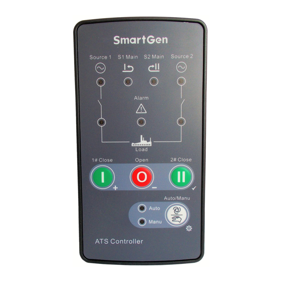
Page 7: Panel Description
HAT160 ATS CONTROLLER USER MANUAL 4. PANEL DESCRIPTION 4.1 FRONT PANEL Fig. 1 Controller Front Panel 4.2 KEY FUNCTION DESCRIPTION Table 4 Button Description Icon Function Description Auto/Manual mode switch; Auto/Manual Enter into lamp test status by pressing for 3s;... -
Page 8: Indicator Description
HAT160 ATS CONTROLLER USER MANUAL 4.3 INDICATOR DESCRIPTION Table 5 Indicator Description Indicators Description Lamp illuminates: 1# power normal; Lamp flashes: 1# power abnormal (over/under voltage, over/under 1# Power Indicator frequency and loss of phase); Lamp off: 1# loss of power Lamp illuminates: 2# power normal;... -
Page 9: Alarms
HAT160 ATS CONTROLLER USER MANUAL 5. ALARMS 5.1 CLOSE/OPEN FAULT ALARM In Auto mode, after the controller sends an open signal, if the controller can also detect close signal when pre-set open delay ends, it will be regarded as open failure and the alarm indicator illuminates at the same time. -
Page 10: Connection
HAT160 ATS CONTROLLER USER MANUAL 6. CONNECTION Fig. 3 Controller Side Panel HAT160 ATS Controller 2020-03-14 Version 1.1 Page 10 of 21... - Page 11 HAT160 ATS CONTROLLER USER MANUAL Table 6 Terminal Wiring Description Terminal Function Note 1# A phase 1# B phase 1# AC 3-phase 4-wire voltage input; If it is single-phase, connect A1 and 1# C phase N1 only, B1 and C1 hang up.
- Page 12 HAT160 ATS CONTROLLER USER MANUAL Fig. 5 Terminals Changing Fig. 6 Fuse Changing HAT160 ATS Controller 2020-03-14 Version 1.1 Page 12 of 21...
- Page 13 HAT160 ATS CONTROLLER USER MANUAL Fig. 7 Programming via LINK HAT160 ATS Controller 2020-03-14 Version 1.1 Page 13 of 21...
-
Page 14: Definition And Range Of Parameters
HAT160 ATS CONTROLLER USER MANUAL DEFINITION AND RANGE OF PARAMETERS Table 7 Parameter Setting Contents and Range (1) Items Range Default Description Priority (1-3) 1: 1# priority 2: 2# priority 3: Spare to each other 1# Volt Abnormal (1-7) 2 (5s) - Page 15 HAT160 ATS CONTROLLER USER MANUAL Items Range Default Description 2: 3s 3: 5s 4: 8s 5: 10s 6: 15s 7: User defined(Default: 5s) Switch Transfer Rest (1-7) 1 (1s) 1: 1s 2: 3s 3: 5s 4: 8s 5: 10s 6: 15s...
- Page 16 HAT160 ATS CONTROLLER USER MANUAL Table 8 Parameter Setting Contents and Range (2) Item Range Default Description 0: 3Phase 4Wire Power Supply (0-1) 1: 1Phase 2Wire Provide standard for over/under volt judgment. Rated Volt (170-270)V Provide standard for close volt and aux. alarm volt.
-
Page 17: Parameters Setting
HAT160 ATS CONTROLLER USER MANUAL 8. PARAMETERS SETTING 8.1 PARAMETERS SETTING MODE In manual mode, pressing for 5s and enter into parameters setting mode and manual indicator flashes; ①, ②, ③, ④ indicators illuminate as Fig. 5. Fig. 8 Parameter Configuration LED Display 8.2 PARAMETERS SETTING... -
Page 18: Typical Application
HAT160 ATS CONTROLLER USER MANUAL Table 9 Parameter Value Comparison No. LED Indicators No. LED Indicators Value Value ① ② ③ ④ ⑤ ⑥ ⑦ 9. TYPICAL APPLICATION Fig. 9 Typical Application Diagram CAUTION: If ATS has trip function, then it must be connected to AL port (AC Volt input). -
Page 19: Verall Dimension And Panel Cutout
HAT160 ATS CONTROLLER USER MANUAL 10. VERALL DIMENSION AND PANEL CUTOUT 10.1 CASE DIMENSION Unit: mm Fig. 10 Case Dimension and Size 10.2 INSTALLATION CUTOUT The controller has three installation ways: panel built-in, internal 35mm slideway and internal screw mounting. Panel built-in and internal screw mounting sizes are as below: Fig. - Page 20 HAT160 ATS CONTROLLER USER MANUAL 10.3 INSTALLATION a)Fixing Clips b) 35mm Slideway c) Screw Mounting HAT160 ATS Controller 2020-03-14 Version 1.1 Page 20 of 21...
-
Page 21: Trobleshooting
HAT160 ATS CONTROLLER USER MANUAL 11. TROBLESHOOTING Table 10 Fault Finding Symptom Possible Remedy Check connections and voltages of 1# and 2# power; Controller inoperative Check F1 or F2 fuse tubes. Switch not activate but Check ATS structure; controller displays normal Check the connections between controller and ATS.
Need help?
Do you have a question about the HAT160 and is the answer not in the manual?
Questions and answers