Table of Contents
Advertisement
Quick Links
Advertisement
Table of Contents

Subscribe to Our Youtube Channel
Related Manuals for RJS Inspector 5000


Summary of Contents for RJS Inspector 5000
- Page 1 Inspector 5000™ Auto Optic Operator’s Guide Manual P/N 003-4500 Revision: C October 2021 THIS MANUAL APPLIES ONLY TO FIRMWARE 1.109 OR LATER RJS Technologies 701 Decatur Ave North, Suite 107 Minneapolis, MN 55427 U.S.A. +1 (763) 746-8034 www.rjs1.com...
- Page 2 Copyrights The copyrights in this manual are owned by RJS. All rights are reserved. Unauthorized reproduction of this manual or unauthorized use of the Inspector 5000 software may result in imprisonment of up to one year and fines of up to $10,000.00 (17 U.S.C.
-
Page 3: Table Of Contents
3.0 INTRODUCTION 3.1 I 5000 D NSPECTOR ESCRIPTION AND EATURES 3.2 M AINTENANCE 3.3 T EMPERATURE PECS 4.0 THE INSPECTOR 5000 AUTO OPTIC 5.0 MAIN MENU SELECTIONS 5.1 P OWER 5.2 S CREEN AVIGATION OR NORMAL OPERATIONS PECIAL UNCTIONS OWER 5.3 F... - Page 4 Inspector 5000™ Auto Optic Operator’s Guide ASER ETTINGS YSTEM ETTINGS ETTINGS 6.0 SCANNING SYMBOLS 6.1 S CANNING ECHNIQUES 6.2 S CANNING ESULTS 6.3 P CREEN 6.4 M ULTIPLE VERAGING ESULTS 7.0 GRADE ANALYSIS SCREEN 7.1 R ESULTS EXPLANATION 7-A (C...
- Page 5 Operator’s Guide Inspector 5000™ Auto Optic EFLECTANCE INIMUM RADITIONAL NALYSIS OLERANCE APPENDIX B (SYMBOLOGY ANALYSIS) YMBOLOGY NALYSIS ARAMETERS B-1 (P ABLE ARAMETER RROR ESSAGE B-2 (P ABLE ARAMETERS HECKED BY YMBOLOGY APPENDIX C (ISO/ANSI DECODABILITY) ISO/ANSI D ECODABILITY ALCULATIONS C-1 (D...
- Page 6 Inspector 5000™ Auto Optic Operator’s Guide APPENDIX G (CODE 128) G-1 (C 128 — S ABLE UBSET G-2 (C 128 — S ABLE UBSET G-3 (C 128 — S ABLE UBSET GS1-128 S YMBOLOGY PECIFICATION APPENDIX H (MAGNIFICATIONS) UPC/EAN M &...
-
Page 7: Preface
1.0 Preface 1.1 Proprietary Statement The Inspector 5000 Operator’s Guide contains proprietary information of RJS. It is intended solely for the use of parties operating and maintaining the equipment described herein. This information may not be used, reproduced, or disclosed to any other parties for any other purpose without the express written permission of RJS. -
Page 8: Documentation Updates
This manual, or any of our manuals, may be updated without notice. 1.6 Copyrights The copyrights in this manual are owned by RJS. All rights are reserved. Unauthorized reproduction of this manual or unauthorized use of the software may result in imprisonment of up to one year and fines of up to $10,000 (17 U.S.C.506). -
Page 9: Batteries
Operator’s Guide Inspector 5000™ Auto Optic 1.8 Batteries The Inspector 5000 has an integrated lithium ion battery pack installed in the unit. The battery is not field replaceable and must be returned to RJS for repair/replacement. Warning: DO NOT use any battery chargers other than the Inspector 5000 battery charger. -
Page 10: Warranty
2.0 Warranty 2.1 General Warranty Warranty information: +1 (763) 746-8034 RJS warrants your Inspector 5000 to be free from defects in material and workmanship for a period of 1 year from the date of shipment from RJS’ factory location. The liability of RJS under this warranty is limited to repairing or replacing the defective part and/or unit. - Page 11 You will be asked to ship the product in its original packing, freight prepaid, with the RMA number visibly written on the outside of the carton to the RJS factory in Minneapolis, MN U.S.A Be sure to include any samples or printouts or other information that will help us to understand the problem.
-
Page 12: Introduction
Inspector 5000™ Auto Optic Operator’s Guide 3.0 Introduction 3.1 Inspector 5000 Description and Features The Inspector 5000 is an advanced technology bar code verifier that makes it easy to decode bar code symbols and to evaluate symbol compliance with industry standards. -
Page 13: Maintenance
Operator’s Guide Inspector 5000™ Auto Optic 3.2 Maintenance To ensure the best possible scanning conditions, keep the display window clean. Use a soft, damp, lint-free cloth to clean the window. Do not use solvents on the unit or on any of the components. -
Page 14: The Inspector 5000 Auto Optic
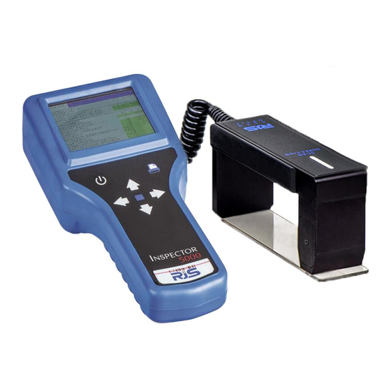
Inspector 5000™ Auto Optic Operator’s Guide 4.0 The Inspector 5000 Auto Optic Battery Charger Serial interface Ethernet Window Keypad Buttons Auto Optic Scanner RJS, Minneapolis, MN 003-4500... -
Page 15: Main Menu Selections
Power button Press and hold the Power button for 1 second to turn On the Inspector 5000. The RJS logo will be displayed for three seconds (on the bottom of the screen is the firmware version), then the Grade screen will displayed. -
Page 16: Screen Navigation
Inspector 5000™ Auto Optic Operator’s Guide 5.2 Screen Navigation The Inspector 5000 screens are navigated by using the seven buttons on the keypad. Power Print Select Up Arrow Right Arrow Left Arrow Down Arrow For normal operations Left Arrow and Right Arrow buttons change which... -
Page 17: Power On
Print button and then press the Up Arrow button Power On When the Inspector 5000 is turned On, the GRADE (grading) screen will display the last bar code inspected: In addition to GRADE, the other screens are ENCODE, PROFILE, and REPORT. -
Page 18: Field Calibration
Inspector 5000™ Auto Optic Operator’s Guide 5.3 Field Calibration The Inspector 5000 requires periodic field calibration. The interval depends on the environment where the bar code verifier is used. Inspector 5000 calibration interval A clean room may be able to go two weeks between calibrations while a dusty, high temperature, high humidity environment may require daily calibration. - Page 19 Operator’s Guide Inspector 5000™ Auto Optic The Inspector 5000 will prompt the user when there is one day before the field calibration will expire: The Inspector 5000 will prompt the user when the field calibration has expired. The inspection results will be...
-
Page 20: Verifying The Inspector 5000 Is Calibrated
From the main calibration screen the unit is setup to measure reflectance. This allows you to check the calibration of the unit by placing the Auto Optic on the RJS Calibration Plaque (P/N 002-7410), white or black fields, and verifying that the reflectance value matches the stated values. -
Page 21: Calibrating The Inspector 5000
Operator’s Guide Inspector 5000™ Auto Optic Calibrating the Inspector 5000 After displaying the Calibration screen, press the Select button to begin calibration: From the reflectance menu press Select button, the Calibrate menu will display: 003-4500 RJS, Minneapolis, MN... - Page 22 Inspector 5000™ Auto Optic Operator’s Guide Remove the Calibration plaque from the protective plastic sleeve. Place the Auto Optic on the white section of the calibration plaque with the inspection hole in the bottom of the Plexiglas plate flat against the surface. Press Select...
- Page 23 Operator’s Guide Inspector 5000™ Auto Optic Place the Auto Optic on the black section of the calibration plaque with the inspection hole in the bottom of the Plexiglas plate flat against the surface. Press Select button and hold auto-optic scanner head still while this...
- Page 24 Inspector 5000™ Auto Optic Operator’s Guide Press Up button to display the reflectometer mode and to verify that the unit is calibrated within tolerance placing the Auto Optic on the light or dark area of the plaque. Reflectance values should be within +/- 2% (of the value written the calibration plaque –...
- Page 25 Operator’s Guide Inspector 5000™ Auto Optic If the Unable to Calibrate screen displays, then repeat the calibration. Note: Once the unit is calibrated, the calibration data will remain saved in memory; the proper Symbol Contrast and Modulation readings depend on field calibration.
-
Page 26: Setup
Inspector 5000™ Auto Optic Operator’s Guide 5.4 Setup Press and hold Print button then press Right Arrow button (at the same time) to bring up the Setup screen: The Down Arrow and Up Arrow buttons allow for changing the selected Setup parameter. -
Page 27: Symbology Settings
Operator’s Guide Inspector 5000™ Auto Optic The Symbology Settings page of the Setup screen: Symbology Settings The first selection allows you to select a range of UPC/EAN symbol magnifications: The magnification options are: - 89 % Mag - 115 % Mag... - Page 28 LOGMARS HIBC 3of9 When using the Inspector 5000 Auto Optic (not applicable to the Inspector 5000 Laser), if either AIAG choice is entered, the scan reflectance profile analysis will performed per the AIAG grading thresholds and display numbers 4.0, 3.0, 2.0, 1.0 and 0.0 in place of the letter grades.
- Page 29 Operator’s Guide Inspector 5000™ Auto Optic The second page Symbology Settings of the Setup screen: The next selection is Datamatrix: This selection is for choosing the Datamatrix sub- specifications for analysis: Standard The next selection is GS1-128 End FNC1: This selection is for choosing the Code 128 sub-...
-
Page 30: Camera Settings
Inspector 5000™ Auto Optic Operator’s Guide The Camera Settings page of the Setup screen: Camera Settings The next selection is Barcode Search: This selection applies ONLY when using the 2D Camera and is for choosing the search order for bar code types:... - Page 31 Operator’s Guide Inspector 5000™ Auto Optic The next selection is 1D Aperture Override: This selection applies ONLY when using the 2D Camera scanner and will replace the selected Auto Optic aperture with the value entered in this field. Auto (based on selected Specification and bar...
-
Page 32: Auto Optic Settings
Inspector 5000™ Auto Optic Operator’s Guide The next selection is Days Between Camera Calibration: The maximum number of days allowable before the system must be field calibrated (2D Camera only). The system will display a warning message one day before expiration and after calibration expires inspection results may be captured but the results will not be stored in the database and may not be printed. - Page 33 Operator’s Guide Inspector 5000™ Auto Optic 3 MIL 0.003 inches *5 MIL 0.005 inches (for Europe and Japan) 6 MIL 0.006 inches 10 MIL 0.010 inches 20 MIL 0.020 inches See Appendix I for an explanation of how to select...
-
Page 34: Laser Settings
The Inspector 5000 will then average the Decodability of all scans captured to provide an overall Decodability average grade. -
Page 35: System Settings
Operator’s Guide Inspector 5000™ Auto Optic The next selection is Laser Comparison Mode: Choices are Off, New, or On. When New is selected, the next bar code scanned will be recorded as the “master” bar code. Then any future bar codes scanned where the... - Page 36 Inspector 5000™ Auto Optic Operator’s Guide Select one of the threshold numeric grades, 0.0 - 4.0. Below this value will be Failing “red” See Appendix A for an explanation of ISO/ANSI grades The next selection is Pass/Fail Screen: This setting can be set to Off or 1 Sec, 2 Sec, 3 Sec, 4 Sec, or 5 Sec.
- Page 37 For printed reports, the day of the week is used with the real-time clock. The next selection is Daylight Savings: The Inspector 5000 has the ability to automatically change the real-time clock to adjust for daylight savings. Choices are Yes or No.
- Page 38 Inspector 5000™ Auto Optic Operator’s Guide The next selection is Set Time: To set the real-time clock time, press the Select button. The Left Arrow and Right Arrow buttons move the cursor and the Up Arrow and Down Arrow buttons increase or decrease the field.
-
Page 39: Exit / Save Settings
Operator’s Guide Inspector 5000™ Auto Optic The Exit / Save page of the Setup screen: Exit / Save Settings The next selection is Restore Default: To restore the Setup parameters back to the system defaults, press the Select button. After pressing the... - Page 40 Inspector 5000™ Auto Optic Operator’s Guide or press Select button again to confirm the changes should be saved and to exit the Setup screen. RJS, Minneapolis, MN 003-4500...
-
Page 41: Scanning Symbols
Operator’s Guide Inspector 5000™ Auto Optic 6.0 Scanning Symbols 6.1 Scanning Techniques Lay the symbol to be scanned on a flat, non- reflective surface. For greatest accuracy scan a symbol more than once, in both directions. Begin a scan from the quiet zone, two inches (5 cm) before the symbol. -
Page 42: Scanning Results
Inspector 5000™ Auto Optic Operator’s Guide 6.2 Scanning Results After a bar code is scanned, the Inspector 5000 will respond with a crisp, chirp (or beep) sound and the Grade screen will be displayed: XX = indicates the aperture size in mils... -
Page 43: Pass/Fail Screen
Operator’s Guide Inspector 5000™ Auto Optic 6.3 Pass/Fail Screen The top section: Pass with a Green background is displayed if the ISO grade is above the Minimum Passing Grade Fail with a Red background is displayed if the ISO... -
Page 44: Multiple Scan Averaging Results
Overall Scan Grade is saved to the database: After the final scan is inspected, the Inspector 5000 will respond with two chirps (or beep sounds). The first is for the final scan and the second is for the overall average bar code scan grade. -
Page 45: Grade Analysis Screen
Operator’s Guide Inspector 5000™ Auto Optic 7.0 Grade Analysis Screen After the symbol is scanned the Grade Analysis Screen will be displayed: This first page of the Grade screen shows: The top section shows the symbology, symbology sub-type, and the encoded bar code data The second section provides the ISO and ANSI bar ... - Page 46 Inspector 5000™ Auto Optic Operator’s Guide Pressing the Down Arrow button will display the additional results This second page of the Grade screen shows: The top section shows the bar code structure information The bottom section is the date and time of the bar ...
-
Page 47: Results Explanation
Operator’s Guide Inspector 5000™ Auto Optic 7.1 Results explanation Line 1 Displays the type of bar code inspected: Symbology ITF14 Case Code Table 7-A (Code Identifier Descriptions) LOGMARS Code 39 symbology AIAG B-1 Code 39 symbology AIAG B 3/4/5/10 Code 39 symbology... - Page 48 Inspector 5000™ Auto Optic Operator’s Guide Table 7-B (Abbreviated Code Identifier Descriptions) Identifier Symbology Type Code 39; B-1 sub-specification for AIAG B345 Code 39; B3, 4, 5, or 10 sub-specification for AIAG Code 39; LOGMARS sub-specification HIBC Code 39; HIBC sub-specification 3 OF 9 Code 39;...
- Page 49 Operator’s Guide Inspector 5000™ Auto Optic Line 3 Displays the ISO numeric grade, the aperture, and the wavelength: OVERALL GRADE 3.4/YY/XXX Note: YY is the aperture and XXX is the wavelength Line 4 Displays the ANSI letter grade, the aperture, and the...
- Page 50 Inspector 5000™ Auto Optic Operator’s Guide Line 7 Displays the ISO/ANSI Worst Decodability character in the barcode: Worst Decodability This is the character in the bar code where the worst Decodability was measured. It is possible the worst Decodability is in the structure part of the bar code (character not shown in the human readable).
- Page 51 Operator’s Guide Inspector 5000™ Auto Optic Line 12 Displays the ISO/ANSI Application Compliance Pass/Fail result (as determined by the Check digit, Sub-Symbology and Industry specifications/standards, Ratio, and Inter- character Gap): Application Compliance Pass Line 13 Displays the ISO/ANSI Reference Decode Pass/Fail...
- Page 52 Barcode Width field. The Inspector 5000 will automatically determine and display the Narrow Bar Width (or Magnification, depending the Symbology). Press the Select button to return to the Grading screen.
- Page 53 Operator’s Guide Inspector 5000™ Auto Optic Line 21 Displays the Reflectance Minimum percentage: Reflectance Minimum Line 22 Displays the Reflectance Maximum percentage: Reflectance Maximum Line 23 Displays the Global Threshold percentage, which is the threshold which determines what is a space and what is a bar in the bar code.
- Page 54 Inspector 5000™ Auto Optic Operator’s Guide Line 27 Displays the Minimum Bar Deviation of all of the bars in the bar code. This value is the deviation from the ideal bar width for the single bar with the smallest print growth...
-
Page 55: Iso Parameter History Results
Operator’s Guide Inspector 5000™ Auto Optic 7.2 ISO Parameter History Results Press the Down Arrow to highlight a parameter to view the history for an individual ISO parameter then press the Select button. Example from the Decodability history results: 003-4500... - Page 56 Inspector 5000™ Auto Optic Operator’s Guide Example from the Defects history results: Press the Power for an explanation of the parameter selected: Press the Power or the Up Arrow to close the explanation window. When finished looking at the parameter history screen,...
-
Page 57: Encode Analysis Screen
Operator’s Guide Inspector 5000™ Auto Optic 8.0 Encode Analysis Screen After the symbol is scanned, the Grade Analysis Screen will be displayed. By pressing the Right Arrow button the Encode Analysis screen will be displayed. Encode analysis screen layout: The top section, left shows encoded bar code data ... - Page 58 Inspector 5000™ Auto Optic Operator’s Guide Pressing the Down Arrow button will display any remaining information for the GS1-128 bar code inspected. RJS, Minneapolis, MN 003-4500...
-
Page 59: Failure Gs1-128 Encode Analysis Screen
Operator’s Guide Inspector 5000™ Auto Optic Failure GS1-128 Encode Analysis Screen If an Error occurs, the cursor will highlight in red the first error and the bottom section will provide a detailed explanation of the error. 003-4500 RJS, Minneapolis, MN... -
Page 60: Failure Upc-A Encode Analysis Screen
Inspector 5000™ Auto Optic Operator’s Guide Failure UPC-A Encode Analysis Screen If an Error occurs, the cursor will jump to the first error and the bottom section will provide a detailed explanation of the error. RJS, Minneapolis, MN 003-4500... -
Page 61: Profile Analysis Screen
Operator’s Guide Inspector 5000™ Auto Optic 9.0 Profile Analysis Screen Press the Select button to display the Profile data 003-4500 RJS, Minneapolis, MN... -
Page 62: An Example Of The Analog Profile Analysis Screen
Inspector 5000™ Auto Optic Operator’s Guide An example of the Analog Profile Analysis screen: The Yellow line identifies the worst case of Modulation The Magenta line identifies the worst case of Decodability The Light Blue line identifies the worst case of ... -
Page 63: An Example Of The Grey-Scale Image Screen
Operator’s Guide Inspector 5000™ Auto Optic The Left Arrow and Right Arrow buttons move the focused area left and right While in the Profile Viewing screens, pressing and holding the Print button and pressing the Down Arrow buttons toggle Profile views – Analog Profile Analysis, Grey-scale... -
Page 64: An Example Of The Black/White Image Screen
Inspector 5000™ Auto Optic Operator’s Guide An example of the Black/White image screen: RJS, Minneapolis, MN 003-4500... -
Page 65: Viewing Saved Inspection Reports
Operator’s Guide Inspector 5000™ Auto Optic 10.0 Viewing Saved Inspection Reports The Inspector 5000 can store in memory over 1,000 bar code inspection results. When the Report screen is selected, the last four inspection results will be displayed. The last inspection result will be highlighted and will show the Date, Time, Grade, Symbology, and Encoded data. -
Page 66: Example Of The Report (Database) Screen After Scrolling To Older Reports
Inspector 5000™ Auto Optic Operator’s Guide Example of the Report (Database) Screen after scrolling to older reports: RJS, Minneapolis, MN 003-4500... -
Page 67: Connect To Other Devices
You may store and print the analysis (and scan reflectance profile) on a Windows PC computer using the optional VCIR software package. Your Inspector 5000 Auto Optic will connect to a computer with a USB-to-Serial adapter or directly to an RS-232 port serial interface cable... -
Page 68: Appendix A (Iso/Ansi Parameter Analysis)
Inspector 5000™ Auto Optic Appendix A Appendix A (ISO/ANSI Parameter Analysis) Table A-1 (Numeric to Letter Grade Conversion) Numeric range Letter grade 3.5 to 4.0 2.5 to <3.5 1.5 to <2.5 0.5 to <1.5 below 0.5 Decodability This parameter can be graded 4.0 to 0.0 (A to F) -
Page 69: Modulation
Symbol contrast is the difference in reflectance values of the “lightest” space (including the quiet zone) and the “darkest” bar of the symbol (the greater the difference, the higher the grade). Note: Bar code colors can have a large effect on this parameter. 003-4500 RJS, Minneapolis, MN... -
Page 70: Defects
Inspector 5000™ Auto Optic Appendix A Defects This parameter can be graded 4.0 to 0.0 (A to F) Defects are irregularities in bars, spaces and quiet zones. For example, a dark spot in a space could cause a low enough reflectance to be mistaken for a bar, and the extra bar would cause a decode error. -
Page 71: Reference Decode
Note: The Inspector 5000 decodes each symbology with a more aggressive algorithm. This enables many symbols to be scanned and decoded even though the Reference Decode grade is a 0.0 (F) The overall symbol grade is averaged for the Reference Decode parameter. -
Page 72: Edge Determination
contrast calculations are valid In the case of an edge determination failure, the Inspector 5000 will force the Decodability grade to 00% (a 0.0 / F grade) Other affected grades will be calculated only for that portion of the symbol which was scanned up to the... -
Page 73: Traditional Bar Analysis Tolerance
The results are normalized to plus or minus 100% tolerance with no specific dimensions. Higher density symbols such as 80% UPC may indicate larger ranges of deviation than low density symbols such as ITF-14 case code. 003-4500 RJS, Minneapolis, MN... -
Page 74: Appendix B (Symbology Analysis)
Inspector 5000™ Auto Optic Appendix B Appendix B (Symbology Analysis) Symbology Analysis Parameters Table B-1 shows error messages that will be displayed for each parameter type checked by the Inspector 5000. Table B-1 (Parameter/Error Message) Parameter Data Analysis Message Ratio Warning Ratio Ratio <2 or more >3.2... - Page 75 Ratio 2 column, applies to Auto Optic 20 mil aperture X = X-dimension/NBW (see Appendix M for definition) R = Ratio in the calculations (see Appendix M for definition) Tolerance is expressed as a fraction of the X-dimension (+/- range) 003-4500 RJS, Minneapolis, MN...
- Page 76 Inspector 5000™ Auto Optic Appendix B Note 2: UPC/EAN tolerances: 80 - 89% = 0.14X 90 - 115% = 0.30X 116 - 150% = 0.34X 151 - 200% = 0.38X RJS, Minneapolis, MN 003-4500...
-
Page 77: Appendix C (Iso/Ansi Decodability)
(ISO15416) and in its Letter grade (ANSI X3.182- 1990) equivalent. ISO/IEC 15416:2016(E) implemented an interpolation method as a way of reducing meaningless grade level fluctuations when small changes in measurements cause a grade to transition between grade levels. 003-4500 RJS, Minneapolis, MN... -
Page 78: Table
33.40 34.59 32.20 33.39 31.00 32.19 29.80 30.99 28.60 29.79 27.40 28.59 26.20 27.39 25.00 26.19 22.50 24.99 20.00 22.49 17.50 19.99 15.00 17.49 12.50 14.99 10.00 12.49 7.50 9.99 5.00 7.49 2.50 4.99 0.00 2.49 RJS, Minneapolis, MN 003-4500... -
Page 79: Appendix D (Reflectance Parameter Grading)
65.99 64.99 63.99 62.99 61.99 60.99 59.99 58.99 57.99 56.99 55.99 54.99 53.99 52.99 51.99 50.99 49.99 48.99 47.99 46.99 45.99 44.99 43.99 42.99 41.99 40.99 39.99 35.99 31.99 27.99 23.99 19.99 15.99 11.99 7.99 3.99 003-4500 RJS, Minneapolis, MN... -
Page 80: Table
63.99 62.99 60.99 59.99 57.99 56.99 54.99 53.99 51.99 50.99 48.99 47.99 45.99 44.99 42.99 41.99 39.99 37.99 35.99 33.99 31.99 29.99 27.99 25.99 23.99 21.99 19.99 17.99 15.99 13.99 11.99 9.99 7.99 5.99 3.99 1.99 RJS, Minneapolis, MN 003-4500... -
Page 81: Table
25.51 26.00 26.01 26.50 26.51 27.00 27.01 27.50 27.51 27.99 28.00 28.49 28.50 28.99 29.00 29.49 29.50 30.00 30.01 100.00 ISO/IEC 15416:2016(E) established that the Defects grade shall be 0.0 for all values greater than 30%. 003-4500 RJS, Minneapolis, MN... -
Page 82: Appendix E (Quiet Zone Analysis)
Operator’s Guide Appendix E (Quiet Zone Analysis) Quiet Zone Analysis The Inspector 5000 trims data gathered during a scan to approximately 10 times the X dimension on each side of a bar code for all symbologies except UPC and EAN. -
Page 83: Appendix F (Specifications)
Specifications There are many specifications that apply to different industries and bar code applications. The Inspector 5000 has the ability to check not only the bar code print quality but also that the Narrow Bar Width (NBW) is within an acceptable range, the Quiet Zones meet the minimum requirements, and that the correct aperture is utilized. -
Page 84: T F-1 (S - S )
ISO 15416 Code 93 ≥ 0.004 & < 0.007 Warning ISO 15416 Code 93 ≥ 0.007 & < 0.013 ISO 15416 Code 93 ≥ 0.013 & < 0.025 ISO 15416 Code 93 ≥ 0.025 ISO 15416 RJS, Minneapolis, MN 003-4500... - Page 85 ISO 15416 Code 93 ≥ 0.004 & < 0.007 Warning ISO 15416 Code 93 ≥ 0.007 & < 0.013 ISO 15416 Code 93 ≥ 0.013 & < 0.025 ISO 15416 Code 93 ≥ 0.025 ISO 15416 003-4500 RJS, Minneapolis, MN...
- Page 86 ISO 15416 Code 93 ≥ 0.004 & < 0.007 Warning ISO 15416 Code 93 ≥ 0.007 & < 0.013 ISO 15416 Code 93 ≥ 0.013 & < 0.025 ISO 15416 Code 93 ≥ 0.025 ISO 15416 RJS, Minneapolis, MN 003-4500...
- Page 87 ISO 15416 Code 93 ≥ 0.004 & < 0.007 Warning ISO 15416 Code 93 ≥ 0.007 & < 0.013 ISO 15416 Code 93 ≥ 0.013 & < 0.025 ISO 15416 Code 93 ≥ 0.025 ISO 15416 003-4500 RJS, Minneapolis, MN...
- Page 88 ISO 15416 Code 93 ≥ 0.004 & < 0.007 Warning ISO 15416 Code 93 ≥ 0.007 & < 0.013 ISO 15416 Code 93 ≥ 0.013 & < 0.025 ISO 15416 Code 93 ≥ 0.025 ISO 15416 RJS, Minneapolis, MN 003-4500...
- Page 89 ISO 15416 Code 93 ≥ 0.004 & < 0.007 Warning ISO 15416 Code 93 ≥ 0.007 & < 0.013 ISO 15416 Code 93 ≥ 0.013 & < 0.025 ISO 15416 Code 93 ≥ 0.025 ISO 15416 003-4500 RJS, Minneapolis, MN...
-
Page 90: Appendix G (Code 128)
3 characters in Subset C (100 - 102) are special characters that are specific to the scanning device. Code 128 also offers the flexibility to “shift” to other subsets in order to combine the “unique” features into one condensed bar code. RJS, Minneapolis, MN 003-4500... - Page 91 The bottom grid (shaded) displays the data on the Inspector’s LCD screen Note: If the bottom grid (shaded) displays two characters (one on top of the other) this is the two rows that will be shown on the Inspector’s LCD screen 003-4500 RJS, Minneapolis, MN...
- Page 92 Appendix G Operator’s Guide Character Set Table G-1 (Code 128 — Subset A) LCD Screen & “ ‘ & “ ‘ < < > > ¥ Code Code FNC3 FNC2 Shft Start Start Start FNC4 FNC1 Stop RJS, Minneapolis, MN 003-4500...
- Page 93 Appendix G Table G-2 (Code 128 — Subset B) Character Set LCD Screen & “ ‘ & “ ‘ < < > > ¥ Code Code FNC3 FNC2 Shft FNC4 → Start Start Start FNC1 Stop 003-4500 RJS, Minneapolis, MN...
- Page 94 Appendix G Operator’s Guide Table G-3 (Code 128 — Subset C) Character Set LCD Screen RJS, Minneapolis, MN 003-4500...
- Page 95 000 to 102). One or two numeric Mod check characters may precede the 3-digit Code 128 Mod check described above. These digits represent the Mod 10 check character(s) that can be included depending on the format. 003-4500 RJS, Minneapolis, MN...
-
Page 96: Gs1-128 Symbology Specification
GS1-128 format and the verifier must have the following Code 128 sub-specifications setting from the Setup screen: For a Standard Code 128 the verifier must have the following Code 128 sub-specifications setting from the Setup screen: RJS, Minneapolis, MN 003-4500... - Page 97 GS1-128 and the first character after the Start character is not a FNC1 then the Format parameter on the Grading screen will be a Failure and on the Encode screen the error will be explained. 003-4500 RJS, Minneapolis, MN...
-
Page 98: Appendix H (Magnifications)
Specifications relative to bar/space tolerances are published for 80% to 200% magnifications. While the Inspector 5000 does not measure the bars and spaces to derive a magnification, it does determine the relative sizes of the elements and therefore the bar width deviations. -
Page 99: Appendix I (Aperture Selection)
Operator’s Guide Appendix J Appendix I (Aperture Selection) The Inspector 5000 Auto Optic has four different aperture (light) sizes that can be used for inspecting bar codes. It is very important that the aperture selected matches the aperture of the bar code scanner that will be used in the supply chain. -
Page 100: Appendix J (Print Functions)
Operator’s Guide Appendix J (Print Functions) Bar code inspection data may be printed (requires optional devices) when the Inspector 5000 is connected to the TP140A printer or to a computer using the VCIR PC software program. The Inspector 5000 will automatically detect which type of printout device is connected. -
Page 101: Vcir Print Screen - Bar Code Inspection From Storage
Operator’s Guide Appendix J VCIR Print Screen – Bar code inspection from storage TP140A Print Screen - Bar code inspection from storage 003-4500 RJS, Minneapolis, MN... -
Page 102: Printout Options
Appendix J Operator’s Guide If the Inspector 5000 is unable detect a printout device the following pop-up message will be displayed: SERIAL PORT ERROR PRINT TO EXIT Printout Options Analysis Only This option prints the Text Analysis data for the last symbol scanned. -
Page 103: Date/Time Range
PRINT REPORTS option and press Select button. The reports will begin printing. To cancel the print job press and hold the Print button and then press the Left Arrow button. 003-4500 RJS, Minneapolis, MN... - Page 104 Appendix J Operator’s Guide Report Range printing screen: Note: Scan reflectance profiles and Bar/Space data are not stored in the database; only the analysis data is stored. RJS, Minneapolis, MN 003-4500...
-
Page 105: Examples Reports
Traditional Traditional Analysis Analysis -100% Tol. +100% --------A+++++++ Traditional Results Print Contrast Signal..91% PASS See Appendix L Required PCS.....75% (Bar code definitions) Element Refl.(MAX)..80% PASS Reflectance(MIN)..07% PASS Pass/Fail Analysis Passing Grade Selected..1.5/C Final Results.....*PASS* 003-4500 RJS, Minneapolis, MN... -
Page 106: Bar Width - Acceptable
Bar Width - Acceptable -100% Tol. +100% ------RRARR+++++ Bar Width - Warning -100% Tol. +100% --------++RRRARR Bar Width - Rejected -100% Tol. +100% --------+++++++R “A” is out of tolerance and off the screen. RJS, Minneapolis, MN 003-4500... - Page 107 Operator’s Guide Appendix J Figure J-2 (Scan Reflectance Profile data) 0% +++++++++ Global Threshold +++++++ 100% (Dark) (Light) 003-4500 RJS, Minneapolis, MN...
-
Page 108: Appendix K (Battery Information)
Appendix K Operator’s Guide Appendix K (Battery Information) Battery Level With the Inspector 5000 turned On: 1. Press hold the Print button and then press the Power to toggle the display to the System Status screen 2. The third line (BATTERY) displays the battery charge level as a percentage 3. -
Page 109: Low Battery Display
60 °C (140 °F) Always check all applicable local, national, and international regulations before transporting a Lithium-Ion battery If the Inspector 5000 has a battery issue it must be returned to RJS for repair 003-4500 RJS, Minneapolis, MN... -
Page 110: Appendix L (Field Firmware Upgrade)
6. Go to your computer and open a web browser and in the address bar enter the IP address written down in Step 5. 7. The Inspector 5000 web server will load the following page: 8. Click the Continue button 9. - Page 111 Appendix L 10. Click Update and then Firmware 11. Select the new .BIN firmware file 12. Click the Update Firmware button 13. Wait for the firmware to be loaded and the “Complete” message to be displayed 003-4500 RJS, Minneapolis, MN...
- Page 112 Appendix L Operator’s Guide 14. Power Off the Inspector 5000 15. Disconnect the Ethernet cable 16. Turn O n the Inspector 5000 RJS, Minneapolis, MN 003-4500...
-
Page 113: Appendix M (Bar Code Definitions)
An element of a bar code symbol whose reflectance is less than the global threshold. A Bar is the dark (reflective) element of a bar-code. (As opposed to a space which is the light reflective element) 003-4500 RJS, Minneapolis, MN... - Page 114 The ratio of the widest bar or space to the narrowest. Bar Reflectance (Rb) The smallest reflectance value in a bar. Bi-directional Code A bar code that can be read left to right or right to left. RJS, Minneapolis, MN 003-4500...
- Page 115 The Decodability grade indicates the amount of error in the width of the most deviant element in the symbol. The less deviation, the higher the grade. Decodability is a measure of print accuracy using the symbology reference decode algorithm. 003-4500 RJS, Minneapolis, MN...
- Page 116 Dimensional Deviation (DD) The measured deviation of bars and/or spaces of a scanned symbol from the specification. Discrete Code A bar code or symbol wherein the spaces between the characters are not part of the data. RJS, Minneapolis, MN 003-4500...
- Page 117 The location where the scan reflectance profile intersects the midpoint between the space reflectance (R space) and bar reflectance (R bar) of adjoining elements. Visual measuring techniques will generally locate the element edge closer to the center of the bar. 003-4500 RJS, Minneapolis, MN...
- Page 118 This effect occurs at all angles of incidence and should not be confused with the grazing angle which is specular reflection often referred to as sheen. RJS, Minneapolis, MN 003-4500...
- Page 119 Inspection Band An area of the bar code symbol where measurements shall be taken spanning from 10% to 90% of the average bar height. 003-4500 RJS, Minneapolis, MN...
- Page 120 Magnification Factor The size of a printed bar code compared to a standard (nominal) size. Maximum Element Reflectance Non-uniformity (ERN max) The largest element reflectance non-uniformity in a scan reflectance profile. RJS, Minneapolis, MN 003-4500...
- Page 121 This condition is affected by aperture size. Note: Since “ink spread” will reduce the width and intensity of single module space within a symbol, this 003-4500 RJS, Minneapolis, MN...
- Page 122 Tolerances are generally specified as positive and negative deviations from this value. No-Read (Non-read, Non-scan) The absence of data at the scanner output after an attempted scan because of no code, defective code or operator error. RJS, Minneapolis, MN 003-4500...
- Page 123 The graphical pattern on a scan reflectance profile which looks like an upside down “U” or “V.” Within a profile a peak represents a space. One or more peaks could also be found within an element representing a reflectance change within an element. 003-4500 RJS, Minneapolis, MN...
- Page 124 “F” is fail). If this parameter is “F” the overall symbol grade will also be “F” regardless of any other parameter. If this parameter is “A” the lowest of the other parameter grades determines the overall symbol grade. RJS, Minneapolis, MN 003-4500...
- Page 125 An electronic device that converts printed information into electrical signals. Scan Reflectance Profile A record (usually graphically represented) of the reflectance measured using the reference reflectivity method as a function of distance across the entire bar code symbol. 003-4500 RJS, Minneapolis, MN...
- Page 126 Specular Reflection Reflection of light from a surface at an angle equal and opposite to the angle of incidence. Start and Stop Characters Characters typically used at the beginning and end of each bar code symbol. RJS, Minneapolis, MN 003-4500...
- Page 127 The symbol grade may be stated as a decimal or converted to a letter grade. A measuring aperture number and nominal wavelength are also specified. Symbology A set of rules for encoding information in a bar code symbol. 003-4500 RJS, Minneapolis, MN...
- Page 128 One or more valleys could also be found within an element representing a reflectance change within an element. Vertical Redundancy The availability of more than one scan path through a bar code symbol. RJS, Minneapolis, MN 003-4500...
- Page 129 Narrow Bar Width (NBW) Zero Suppression Technique used to shorten UPC symbols by omitting zeros from the bar-code. Z Dimension achieved width the narrow elements. Computation of Z is accomplished using different factors for some symbologies. 003-4500 RJS, Minneapolis, MN...
Need help?
Do you have a question about the Inspector 5000 and is the answer not in the manual?
Questions and answers