
Related Manuals for RJS SV Series


Summary of Contents for RJS SV Series
- Page 1 SV Series Scanner/Verifier Operator’s Guide P/N 002-7942 1/22/01 a subsidiary of Printronix, Inc. 14600 Myford Road Irvine, CA 92606 +1 (714) 368-2781 fax: +1 (714) 368-2354 www.rjs1.com...
-
Page 2: Table Of Contents
Table of Contents PREFACE ..............................2 WARRANTY..............................5 INTRODUCTION............................6 LASER BEAM............................... 6 RESET BUTTON............................6 Turn Off Laser Beam..........................6 Perform Calibration ............................ 7 Reset Ports..............................7 I/O CONNECTOR ............................7 + 5 VDC Power Input..........................7 Sync Inputs ..............................7 Edge Sync Mode............................. - Page 3 Label Setup Commands - L ........................27 Output Mode Selection Commands - O....................30 Output Port Setup Commands - P......................31 System Control Commands - S ......................33 OUTPUT INTERFACE MODES DESCRIPTIONS ................... 34 Mode 00 (~LV00)............................. 35 Mode 01 (~LV01)............................. 35 Mode 02 (~LV02).............................
- Page 4 The copyrights in this manual are owned by RJS. All rights are reserved Unauthorized reproduction of this manual or unauthorized use of the SV Series software may result in imprisonment of up to one year and fines of up to $10,000.00 (17 U.S.C. 506). Copyright violations may be subject to civil liability.
-
Page 5: Preface
PREFACE Proprietary Statement This RJS SV Series Operator’s Guide contains proprietary information of RJS. It is intended solely for the use of parties operating and maintaining the equipment described herein. This information may not be used, reproduced, or disclosed to any other parties for any other purpose without the express written permission of RJS. - Page 6 • Use the SV Series only with UL-Listed Bar Code Printers, Applicators, conveyors, etc. • The following laser light Caution labels must be affixed to your SV Series verifier: If they are not, contact RJS immediately.
-
Page 8: Warranty
WARRANTY General Warranty RJS warrants the SV Series to be free from defects in material and workmanship for a period of 1 year, under normal use and service, from the date of shipment from RJS’ factory location. The liability of RJS under this warranty is limited to repairing or replacing the defective part and/or unit. -
Page 9: Introduction
INTRODUCTION The RJS SV Series of Scanner/Verifiers is designed to be a universal system component that can analyze linear bar code print quality, check encoded data and detect system failures. In its basic mode of operation, an SV unit acts similar to a normal fixed position scanner by automatically decoding bar codes as they pass through its laser beam. -
Page 10: Perform Calibration
+ 5 VDC Power Input The SV Series requires + 5 Volts DC, +/- 0.25 Volt. Maximum current consumption is 1 amp. The voltage input must be connected to pin 12 and the ground input should be connected to pin 13 on the I/O connector. -
Page 11: Edge Sync Mode
3. Counting ceases upon receipt of the trailing edge of a sync signal. The SV Series determines that at least the number of bar codes expected (programmed) during the sync period have been fully decoded. -
Page 12: Communication Sync Commands
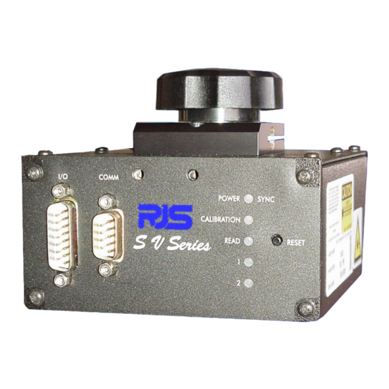
Five LED’s are included on the SV Series back panel. Power/Sync LED This LED is illuminated green whenever power is applied to the SV Series. Upon receipt of any sync input (hardware or serial communications) the LED will blink yellow for approximately 100 milliseconds. -
Page 13: Serial Port Pin-Out
SERIAL PORT TRANSMISSION FORMAT The following data transmission format is standard in the SV Series. This is the format used by ScanVision software for setup and monitoring of SV Series data. All parameters analyzed for each bar code scanned are... - Page 14 Absolute X dimension in 0.1 mil (.0001 inch) resolution. Example: a value of 120 represents a 12 mil X dimension. Overall ANSI method symbol grade (numeric) Ave over all decoded scans. Example: 26 = 2.6 Bar code decoding direction: Forwards(0) or Backwards(1) 000-999;...
-
Page 15: Installation And Setup
UPC-E w/add-on (5) INSTALLATION AND SETUP Scanner positioning and proper system setup are extremely important for proper SV Series operation. Positioning is important in order to provide accurate analyses. The scan distance must be set accurately to achieve the proper beam focus in order to detect printer flaws and failures such as a worn ribbon (matrix printing), low toner (laser printing), voids (flexo printing), burned pixels (thermal printing), etc. -
Page 16: Scanner Positioning
Scanner Positioning Each SV Series has an attached label that indicates the type of scanner, focus distance and recommended scan angle. Use the scan distance and scan angle information to mount the scanner per Figure 2. Figure 2 – Scanner Positioning Notes: 1. -
Page 17: Bar Code Travel Direction
Bar Code Travel Speed Considerations A bar code should be present in the beam for at least five scans for most reliable operation. The SV Series performs a minimum of 100 scans/analyses per second. At that rate, each analysis is accomplished in 10 milliseconds max. -
Page 18: Ladder Direction
A calibration symbol is supplied with each SV unit as a standard component. Store it in a clean location. The SV Series can be calibrated using either of the two following procedures: Procedure 1: 1. -
Page 19: Setup Procedure
Setup Procedure It is highly recommended that RJS ScanVision be used to set up SV Series units. This Windows based software is available free of charge from RJS. The alternative is to use SV Command Language through a host computer. - Page 20 *This step is not mandatory, but highly recommended. Scanner focus is dependent on the scan distance. Good focus maximizes the SV Series’s ability to detect printer errors and failures. If this step is omitted, take extra precaution in setting and measuring the scan distance.
-
Page 21: Adjusting Scanner Gain And Offset
Scanner gain and offset adjustment via commands is available in SV units that have the “A” circled on the label that indicates focus distance. The adjustment capability is useful for adapting the unit to various material types and scanning angles during the setup procedure. Knowledge of RJS ScanVision software is required for best understanding of the following description. -
Page 22: Technical Specifications
All Models - 4 bar codes across max. (picket fence direction) Scanner Options Scanners can incorporate options for special optics and/or be focused for special applications. Contact RJS Technical Support and describe your application for assistance. Below are two standard options available. -
Page 23: Power
A hardware input is the most common sync source for this mode. Note: When in this sync mode, the sync input is a background application. The SV Series will scan, analyze and report on bar codes as they pass through the beam in this mode, regardless if a sync signal is sensed. -
Page 24: Sync Mode - Stationary Bar Codes
If this mode is used, the SV Series can still detect many print errors because of its partial decode analysis capability. This algorithm can detect a bar code start or stop character and two adjacent characters. This part of a code is usually present in most print failure situations. -
Page 25: Sv Command Language
Symbology Type (scanner decoder function) % Decode (multiple scanning parameter) Global Threshold (ANSI method parameter) Modulo Check Digits (mandatory symbology and optional application parameters) Encoded Data (scanner decoder function) SV COMMAND LANGUAGE All commands to the verifier begin with a tilde, ‘~’, followed by one or more alphanumeric characters. The ‘~’... - Page 26 … bbb… - Fill characters prior to the Data Match text. These characters must match the character defined by b in the command. …mmm… - Data Match Character Field. This can be from 1 to 32 characters. These define the exact characters that must be matched.
-
Page 27: Relationship Between ~Bc And ~Br Commands
This command instructs the verifier to report all parameters of the event that caused this port to go active. # = 1 through 8 (port ID) Inquire software version. Commands the verifier to transmit the SV Series firmware version to the host in the following datapacket format:... -
Page 28: Hardware Configuration Commands - H
hexadecimal value ‘4’ - identifies the beginning of the datapacket response The following character string between the quotes: ‘Version: ‘ Five alphanumeric characters that specify the version number. They can include trailing spaces. (See example below.) hexadecimal value ‘5’ - identifies the end of the datapacket response Example return using Scanvision: Version: X244 Hardware Configuration Commands - H... - Page 29 Display the verifier parameters The format of the reply is: hexadecimal value ‘4’ - identifies the beginning of the datapacket response. A list of text strings like the one shown in the example. Each string is terminated by a two character sequence: ‘\r’...
-
Page 30: Label Setup Commands - L
For offset, the higher the value, the lower the offset. Example: ~Hd201145 sets the scanner offset value to 145. These commands are best used in conjunction with RJS ScanVision software. Please refer to the Setup Procedures Section in this guide for descriptions on the use of these commands. - Page 31 1 = Mod 10 check digit for Interleaved 2 of 5 Note: additional subsymbology choices will be added as applications require. Contact RJS for details. Example: ~LF41 = check mod 10 check digit in last location for any I 2 of 5 symbol analyzed...
- Page 32 6- CBAR- IN min chars: 032 number bc: 099 ~LN## Set Minimum Number of Bar Codes Per Label (i.e., per sync period) This command instructs the verifier on how many bar codes it is expected to read and analyze during a sync period.
-
Page 33: Output Mode Selection Commands - O
This command sets the output interface mode of the unit. Modes have fixed port activation logic defined by specific applications. Some activation parameters are programmable. Custom modes are available – contact RJS technical Support. Modes included in standard SV Series are described in the Output Interface Modes Descriptions Section. Example: ~LV01 sets mode 01. -
Page 34: Output Port Setup Commands - P
1 =Standard transmission format modified; analysis parameters a through N included, but encoded data is formatted as data characters only rather than all symbol characters. The data consists only of printable ASCII characters and does not include any mandatory symbol characters such as stop, start and symbol mod check characters. - Page 35 Ref. Decode Flag Character Format Flag Partial Decode Flag Data Match Flag Illegal Position Flag *The data format for negative numbers ranging from –100 to –1 is 0 to 99. For example: −100=0; −95=5; −10=90; 0=100; 25=125; 95=195; 100=200 ~PPpiiaaa Port action parameters.
-
Page 36: System Control Commands - S
~PR#### Port/LED reset state #### = four hexadecimal digits Each port and led are represented by a binary digit in the four hexadecimal digits as follows: Indicator Digit value Power indicator 0x0001 Read LED 0x0002 LED1 0x0004 LED2 0x0008 Port 1 0x0010 Port 2 0x0020... -
Page 37: Output Interface Modes Descriptions
To use the target values encoded in the calibration symbol set this value to 00. OUTPUT INTERFACE MODES DESCRIPTIONS Output interface modes are used to set the SV Series for particular ways to activate output ports. The mode is set via the ~LV## command. The following list describes the standard output interface modes available... -
Page 38: Mode 00 (~Lv00)
Custom modes are available – contact RJS Technical Support. After programming the SV unit for the desired port activation parameters, it is recommended to review them. When using ScanVison, this can be done via the Transmit SV Commands Window by sending the ~HT command to review all scanner settings, and sending the ~PT8 command to review all quality parameter failure threshold settings. - Page 39 This command allows partial decodes to activate the output ports ~LQ0 This command disables partial decodes to activate output ports. NOTE: In SV firmware versions x238 and lower, ~LQ commands are not implemented and the command ~HQ1 must be used to disable partial decodes from activating ports. In this case the standard data transmission format is modified and ScanVision will not display data characters correctly.
-
Page 40: Mode 02 (~Lv02)
Mode 02 (~LV02) Mode 02 I/O operation Envelope type sync input on pin 4 Port 3: per sync type. The state of this output must be stable within 12.5 milliseconds after the sync input goes low (trailing edge.) Typical time for stability will be less than 7.5 milliseconds if the sync is received when a bar code or complex graphic is not in the beam. -
Page 41: Mode 03 (~Lv03)
~LDxx This command sets the % decode threshold for a passing condition. If analyzing poorly printed symbols, it is recommended that partial decodes be enabled at the decoder level when this command is enabled. xx = failure threshold. Example ~LD75: if 74 % or less of scans on a code were not fully decoded, this sets a failure for this parameter. - Page 42 Sync polarity – programmable (~LP#) Use ~PR0210 for proper port initialization. Port 1 will go active OFF (no current) on an error condition. Port 2 will go active ON (sink current) on an error condition. Port 3 will operate in per analysis pulse mode. Active polarity ON (sink current), approximately 500 millisecond duration.
-
Page 43: Mode 16 (~Lv16)
This command sets the % decode threshold for a passing condition. If analyzing poorly printed symbols, it is recommended that partial decodes be enabled at the decoder level when this command is enabled. xx = failure threshold. Example ~LD75: if 74 % or less of scans on a code were not fully decoded, this sets a failure for this parameter. - Page 44 ~PB8 rather than ~PB1, ~PB2, etc. for each individual port. Other commands, such as mode commands are also available. The commands most useful for this system application are described below. Please see the SV Series Operator’s Guide for additional command description details. ~LV16 This command sets the proper mode for this operation.
-
Page 45: Mode 17 (~Lv17)
xx = failure threshold. Example ~LD75: if 74 % or less of scans on a code were not fully decoded, this sets a failure for this parameter. ~PB816xxx100 This command sets the minimum percent of scans on a code which calculate good quiet zones to determine an acceptable quiet zone analysis. - Page 46 ~PB8 rather than ~PB1, ~PB2, etc. for each individual port. Other commands, such as mode commands are also available. The commands most useful for this system application are described below. Please see the SV Series Operator’s Guide for additional command description details. ~LV17 This command sets this mode of operation.
- Page 47 ~LQ1 This command allows partial decodes to activate the output ports ~LQ0 This command disables partial decodes to activate output ports. ~LAxx This command sets the passing threshold for the Overall ANSI method Symbol Grade. For example: ~LA28 causes an Overall Symbol Grade of 2.7 or lower calculated for the code analyzed to set a failure condition for this parameter.
-
Page 48: Mode 18 (~Lv18)
This command sets the minimum number of codes to be read during a sync period. ## = the number of codes. For example: ~LN02 causes a No Read condition to be set if less than 2 bar codes are fully decoded during a sync interval. - Page 49 ~PB8 rather than ~PB1, ~PB2, etc. for each individual port. Other commands, such as mode commands are also available. The commands most useful for this system application are described below. Please see the SV Series Operator’s Guide for additional command description details. ~LV18 This command sets this mode of operation.
-
Page 50: Mode 19 (~Lv19)
This command sets the threshold for the ANSI Defects calculation on a code to set a failure condition. The field xxx is the passing threshold for the calculation. For example: if xxx = 025, a Defects analysis of 26% or higher will cause a failure condition for this parameter. ~PB802xxx100 This command sets the threshold for the ANSI Decodability calculation on a code to set a failure condition. - Page 51 ~PB8 rather than ~PB1, ~PB2, etc. for each individual port. Other commands, such as mode commands are also available. The commands most useful for this system application are described below. Please see the SV Series Operator’s Guide for additional command description details. ~LV19 This command sets this mode of operation.
- Page 52 This command sets the passing threshold for the Overall ANSI method Symbol Grade. For example: ~LA28 causes an Overall Symbol Grade of 2.7 or lower calculated for the code analyzed to set a failure condition for this parameter. ~LDxx This command sets the % decode threshold for a passing condition. If analyzing poorly printed symbols, it is recommended that partial decodes be enabled at the decoder level when this command is enabled.
- Page 53 This command overrides the ~LN## command if the number of codes set does not = 00. If ~LZ## is set to ~LZ00, the ~LN## command takes precedence. This command stores all parameters into non-volatile memory. This command should be the last command sent after parameters are programmed via the above commands.
-
Page 54: Ansi Parameter Grade Thresholds
ANSI PARAMETER GRADE THRESHOLDS ANSI parameter fail thresholds are set in the SV Series by commands requiring numeric settings that correlate to the parameter calculations. Below are descriptions of how the numeric calculations are divided into letter grades per the ANSI Bar Code Quality Specification A <...
Need help?
Do you have a question about the SV Series and is the answer not in the manual?
Questions and answers