
Subscribe to Our Youtube Channel
Related Manuals for IEI Technology DRPC-240-TGL


Summary of Contents for IEI Technology DRPC-240-TGL
- Page 1 MODEL: DRPC-240-TGL Embedded System with Intel® Tiger Lake-U CPU, 8 GB DDR4 SO-DIMM, M.2 Slot, PCIe x4 Slot, RS-232, RS-422/485, HDMI, DP++ and RoHS User Manual Rev. 1.00 – 2022-08-17...
- Page 2 DRPC-240-TGL Embedded System Revision Date Version Change 2022-08-17 1.00 Initial Release Page II...
- Page 3 DRPC-240-TGL Embedded System Copyright COPYRIGHT NOTICE The information in this document is subject to change without prior notice in order to improve reliability, design and function and does not represent a commitment on the part of the manufacturer. In no event will the manufacturer be liable for direct, indirect, special, incidental, or consequential damages arising out of the use or inability to use the product or documentation, even if advised of the possibility of such damages.
- Page 4 DRPC-240-TGL Embedded System Manual Conventions WARNING Warnings appear where overlooked details may cause damage to the equipment or result in personal injury. Warnings should be taken seriously. CAUTION Cautionary messages should be heeded to help reduce the chance of losing data or damaging the product.
-
Page 5: Table Of Contents
DRPC-240-TGL Embedded System Table of Content 1 INTRODUCTION ......................11 1.1 O ........................ 12 VERVIEW 1.2 F ......................... 13 EATURES 1.3 M ....................13 ODEL ARIATIONS 1.4 T ..................14 ECHNICAL PECIFICATIONS 1.5 F ......................16 RONT ANEL 1.6 R ...................... - Page 6 DRPC-240-TGL Embedded System Ethernet Connection ..................36 USB Device Connection ................. 37 DB-9 RS-232/422/485 Serial Port Connection ..........38 Power Input, 3-pin Terminal Black ..............39 ATX/AT Mode Selection ................. 40 Remote Power Connector ................40 3.14 P ................41...
- Page 7 DRPC-240-TGL Embedded System A.1.2 Anti-static Precautions ................... 119 A.1.3 Product Disposal ................... 120 A.2 M ............121 AINTENANCE AND LEANING RECAUTIONS A.2.1 Maintenance and Cleaning ................121 A.2.2 Cleaning Tools ....................121 B REGULATORY COMPLIANCE ................122 C HAZARDOUS MATERIALS DISCLOSURE ............127...
- Page 8 List of Figures Figure 1-1: DRPC-240-TGL ......................12 Figure 1-2: DRPC-240-TGL Front Panel..................16 Figure 1-3: DRPC-240-TGL Rear Panel ..................17 Figure 1-4: DRPC-240-TGL Right Side Panel ................17 Figure 1-5: DRPC-240-TGL Dimensions ..................18 Figure 1-6: DRPC-240-TGL Dimensions ..................19 Figure 3-1: Removing the Back Cover ..................27 Figure 3-2: Removing the HDD Bracket ..................27...
- Page 9 DRPC-240-TGL Embedded System Figure 4-2: System Motherboard (Rear) ..................47 Figure 4-3: SATA Connector .......................48 Figure 4-4: SIM Card Slot (SIM1) ....................49 Figure 4-5: HDMI Connector ......................53 Figure 4-6: DP Connector ......................54 Figure 4-7: USB 2.0 Connector ....................55 Figure 4-8: RS-232 Connector .....................55 Figure 4-9: RJ-45 Connector .......................56...
- Page 10 DRPC-240-TGL Embedded System List of Tables Table 1-1: Model Description .......................13 Table 1-2: Technical Specifications ....................15 Table 2-1: Packing List .........................22 Table 2-2: Optional Packing List ....................23 Table 3-1: RJ-45 Ethernet Connector LEDs ................37 Table 3-2: RS-232 (COM1-2) & RS-232/422/485 (COM3-4) Connector Pinouts .......38 Table 3-3: Power LED Indicators Description ................42...
-
Page 11: Introduction
DRPC-240-TGL Embedded System Chapter Introduction Page 11... -
Page 12: Overview
DDR4 SO-DIMM memory. It is designed for harsh environment applications, and supports DIN rail mounting method. The DRPC-240-TGL accepts a wide range of DC power input (12V ~ 28V), allowing it to be powered anywhere. It is equipped with two USB 3.2 Gen 2 (10Gb/s), two USB 2.0, four 2.5GbE, two RS-232 ports, two RS-422/485 ports, one HDMI and one DisplayPort++ to... -
Page 13: Features
DRPC-240-TGL Embedded System 1.2 Features The DRPC-240-TGL features are listed below: Intel® Tiger Lake-U processor Two DDR4 SO-DIMM memory slot(8GB pre-installed) 1 x 2.5" SATA 6Gb/s HDD/SSD bay 2 x USB 3.2 Gen 2 (10Gb/s) port ... -
Page 14: Technical Specifications
DRPC-240-TGL Embedded System 1.4 Technical Specifications The DRPC-240-TGL technical specifications are listed below. DRPC-240-TGL- DRPC-240-TGL- DRPC-240-TGL- Model U-i7CS U-i5CS U-CCS Color Black Dimensions 81 x 150 x 190 81 x 150 x 190 81 x 150 x 190 (WxDxH) (mm) -
Page 15: Table 1-2: Technical Specifications
DRPC-240-TGL Embedded System 1 x Power button 1 x Reset button 1 x AT/ATX switch Others 1 x Power LED (green) 1 x HDD LED (yellow) 4-pin external system fan connector 1 x 2230 A key (PCIe x1, USB 2.0) Expansions 1 x 3042/52/80 B key (PCIe x2, USB, 3.0, USB 2.0) -
Page 16: Front Panel
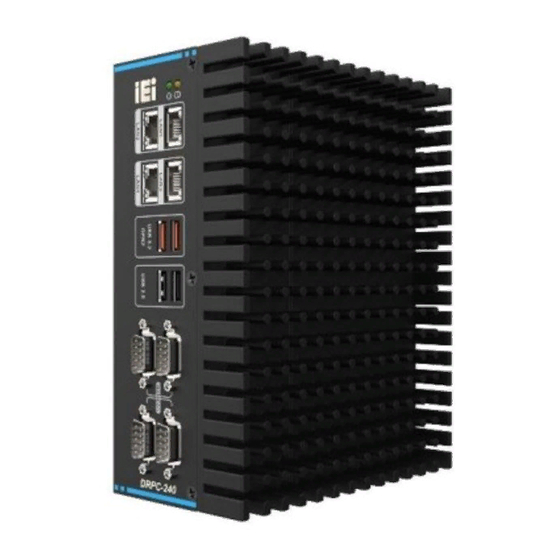
DRPC-240-TGL Embedded System 1.5 Front Panel The DRPC-240-TGL front panel contains: 4 x 2.5GbE LAN 2 x USB 3.2 Gen 2 port 2 x USB 2.0 port 2 x RS-232 port 2 x RS-422/485 port Figure 1-2: DRPC-240-TGL Front Panel 1.6 Rear Panel... -
Page 17: Right Side Panel
DRPC-240-TGL Embedded System Figure 1-3: DRPC-240-TGL Rear Panel 1.7 Right Side Panel The DRPC-240-TGL right side panel contains: 1 x System fan Figure 1-4: DRPC-240-TGL Right Side Panel Page 17... -
Page 18: Dimensions
DRPC-240-TGL Embedded System 1.8 Dimensions The physical dimensions of the DRPC-240-TGL series are shown below. With fan: Figure 1-5: DRPC-240-TGL Dimensions Page 18... -
Page 19: Figure 1-6: Drpc-240-Tgl Dimensions
DRPC-240-TGL Embedded System With expansion layer: Figure 1-6: DRPC-240-TGL Dimensions Page 19... -
Page 20: Unpacking
DRPC-240-TGL Embedded System Chapter Unpacking Page 20... -
Page 21: Unpacking
If some of the components listed in the checklist below are missing, please do not proceed with the installation. Contact the IEI reseller or vendor you purchased the DRPC-240-TGL from or contact an IEI sales representative directly. To contact an IEI sales representative, please send an email to sales@ieiworld.com. -
Page 22: Table 2-1: Packing List
DRPC-240-TGL Embedded System Quantity Item and Part Number Image DRPC-240-TGL series DIN rail mounting kit Screw pack Table 2-1: Packing List Optional Wi-Fi module (P/N: EMB-WIFI-KIT02I3-R10) Power adapter (120W) (P/N: 63040-010120-300-RS) Power adapter (220W) (P/N: 63040-010230-000-RS) Page 22... -
Page 23: Table 2-2: Optional Packing List
DRPC-240-TGL Embedded System Optional Power cable (P/N: 32102-054800-100-RS) Power cord (P/N: 32702-000400-200-RS) PoE power module (P/N: GPOE-DRPC-240-R10) 1-slot expansion chassis with riser card (P/N: TXC-DRPC-240-1S-R10) External fan module (P/N: TXC-DRPC-240-1S-R10) DIO cable (P/N: 32031-000600-100-RS) Table 2-2: Optional Packing List Page 23... -
Page 24: Installation
DRPC-240-TGL Embedded System Chapter Installation Page 24... -
Page 25: Anti - Static Precautions
Electrostatic discharge (ESD) can cause serious damage to electronic components, including the DRPC-240-TGL. Dry climates are especially susceptible to ESD. It is therefore critical that whenever the DRPC-240-TGL is accessed internally, or any other electrical component is handled, the following anti-static precautions are strictly adhered ... -
Page 26: Back Cover Removal
Before installing or maintaining the internal components, the back cover must be removed from the DRPC-240-TGL. Follow the steps below to complete the task. Step 1: Turn the DRPC-240-TGL over and remove the 6 screws on the back cover. Step 2: Take off the back cover (Figure 3-1). -
Page 27: Hdd Bracket Removal
DRPC-240-TGL Embedded System Figure 3-1: Removing the Back Cover 3.4 HDD Bracket Removal The HDD bracket must be removed first before installing a hard disk or M.2 modules. Step 1: Remove the 3 screws on the side panels. Remove the HDD bracket as indicated by the arrows in Figure 3-2. -
Page 28: Memory Installation
Figure 3-3: Memory Installation 3.6 Storage Installation The DRPC-240-TGL supports two types of storage, one M.2 B Key & one 2.5" SSD. Before installing a M.2 SSD or 2.5" SSD/HDD, please follow the steps described in Section 3.4 to remove the HDD bracket. -
Page 29: Ssd Installation
Remove the onboard M.2 retention screw, and adjust the stud position according to the size of your M.2 SSD. Note that you must purchase a M.2 SSD that is compliant with the specification of the DRPC-240-TGL. Step 2: Insert the M.2 SSD into the M.2 slot and fasten the screw removed previously (Figure 3-4). -
Page 30: Wi-Fi Module Installation (Optional)
DRPC-240-TGL Embedded System Figure 3-5: HDD Installation 3.7 Wi-Fi Module Installation (Optional) The Wi-Fi module is an optional accessory. You can purchase it from IEI or other providers. Note that you have to purchase Wi-Fi module, internal antenna and external antenna. It is suggested to purchase an internal antenna longer than 200mm. -
Page 31: Poe Power Module Installation (Optional)
DRPC-240-TGL Embedded System Figure 3-6: Wi-Fi Module Installation 3.8 PoE Power Module Installation (Optional) This PoE power module provides PoE function to the 4 LAN ports of the DRPC-240 to offer a maximum power consumption of 60W, and a single port power consumption of 15W. To install the PoE module, follow the steps below. -
Page 32: External Fan Module Installation (Optional)
3.9 External Fan Module Installation (Optional) When encountering high performance and high heat that need additional cooling, the optional external fan can help the DRPC-240-TGL solve the thermal problem. To install the optional external fan, follow the steps below. Step 1: Remove the 4 screws (2 on the front panel, 2 on the rear panel) on the DRPC- 240-TGL as shown in the figure below. -
Page 33: Adding External I/O Ports (Optional)
DRPC-240-TGL Embedded System Figure 3-8: External Fan Module Installation 3.10 Adding External I/O Ports (Optional) Additional two external I/O ports can be added on the DRPC-240-TGL, such as DIO. To do this, follow the steps below. Step 1: Connect one end of the I/O cable to the pin headers on the motherboard Step 2: Remove the DB9 knockout reserved on the chassis. -
Page 34: Expansion Chassis Installation (Optional)
DRPC-240-TGL Embedded System 3.11 Expansion Chassis Installation (Optional) The DRPC-240-TGL provides an option for adding PCIe x4 function, which is achieved by installing the expansion chassis (P/N: TXC-DRPC-240-1S-R10). The installation steps are described below. Step 1: Before installing the expansion chassis, ensure the fan wire inside the system will not be pressed or damaged (adjust the wiring if necessary). -
Page 35: Back Cover Installation
DRPC-240-TGL Embedded System Figure 3-10: Expansion Chassis Installation 3.12 Back Cover Installation After installing all the internal components of the system, the back cover must be re- installed. Use the 6 screws previously removed to secure the back cover to the chassis ( Figure 3-11). -
Page 36: External Device Connection
Figure 3-14. Step 2: Align the connectors. Align the RJ-45 connector on the LAN cable with one of the RJ-45 connectors on the DRPC-240-TGL See Figure 3-13. Figure 3-13: LAN Connection Step 3: Insert the LAN cable RJ-45 connector. Once aligned, gently insert the LAN cable RJ-45 connector into the on-board RJ-45 connector. -
Page 37: Usb Device Connection
2.5 Gbps connection Table 3-1: RJ-45 Ethernet Connector LEDs USB Device Connection The DRPC-240-TGL has two USB 3.2 and two USB 2.0 ports. To connect a USB device, please follow the instructions below. Step 1: Located the USB connectors. The locations of the USB connectors are shown in Chapter 1. -
Page 38: Rs-232/422/485 Serial Port Connection
DRPC-240-TGL Embedded System Figure 3-15:USB Connection DB-9 RS-232/422/485 Serial Port Connection The DRPC-240-TGL has two RS-232 serial ports and two RS-422/485 serial ports. The pinouts for the serial ports are listed in the Table 3-2. PIN NO. RS232 RS422 RS485... -
Page 39: Power Input, 3-Pin Terminal Black
DRPC-240-TGL Embedded System Figure 3-16: DB-9 RS-232/422/485 Serial Port Connector Figure 3-17: Serial Device Connection Power Input, 3-pin Terminal Black The power connector connects the leads of a 12 V~28 V DC power supply into the terminal block. Make sure that the power and ground wires are attached to the correct sockets of the connector. -
Page 40: Atx/At Mode Selection
DRPC-240-TGL Embedded System ATX/AT Mode Selection AT and ATX power modes can both be used on the DRPC-240-TGL. The selection is made through an AT/ATX switch on the top panel as shown below (Figure 3-19). Figure 3-19: ATX/AT Mode Selection... -
Page 41: Powering On/Off The System
DRPC-240-TGL Embedded System 3.14 Powering On/Off the System WARNING: Make sure a power supply with the correct input voltage is being fed into the system. Incorrect voltages applied to the system may cause damage to the internal electronic components and may also cause injury to the user. -
Page 42: Figure 3-22: Power Input
DRPC-240-TGL Embedded System Figure 3-22: Power Input Figure 3-23: Power LED Power LED Indicator Description Standby mode. Breathing Orange Power-on mode. Solid blue Table 3-3: Power LED Indicators Description NOTE: The power LED turns off when the power cable is unplugged from the system. -
Page 43: Available Drivers
DRPC-240-TGL Embedded System 3.16 Available Drivers All the drivers for the DRPC-240-TGL are available on IEI Resource Download Center (https://download.ieiworld.com). Type DRPC-240-TGL and press Enter to find all the relevant software, utilities, and documentation. Figure 3-24: IEI Resource Download Center Driver Download To download drivers from IEI Resource Download Center, follow the steps below. - Page 44 DRPC-240-TGL Embedded System Step 3: Click the driver file name on the page and you will be prompted with the following window. You can download the entire ISO file ( ), or click the small arrow to find an individual driver and click the file name to download (...
-
Page 45: System Motherboard
DRPC-240-TGL Embedded System Chapter System Motherboard Page 45... -
Page 46: Ovreview
DRPC-240-TGL Embedded System 4.1 Ovreview The connectors and jumpers of the system motherboard are listed in the following sections. Layout The following diagram shows the locations of the internal/external connectors and jumpers on the motherboard. Figure 4-1: System Motherboard (Front) -
Page 47: Internal Peripheral Connectors
DRPC-240-TGL Embedded System Figure 4-2: System Motherboard (Rear) 4.2 Internal Peripheral Connectors The table below shows a list of the connectors on the motherboard. Label Function SATA Serial ATA connectors SIM1 SIM card connector M2_A1 M.2 A key card connector M2_B1 M.2 B key card connector... -
Page 48: Sata Connector (Sata1)
DRPC-240-TGL Embedded System SATA Connector (SATA1) The DRPC-240-TGL has one SATA connector for SATA device connection. PIN NO. DESCRIPTION PIN NO. DESCRIPTION Table 4-2: SATA Connector Pinoouts (SATA1) Figure 4-3: SATA Connector SIM Card Slot (SIM1) PIN NO. DESCRIPTION SIM_VCC... -
Page 49: A-Key Card Slot (M2_A1)
DRPC-240-TGL Embedded System Figure 4-4: SIM Card Slot (SIM1) M.2 A-Key Card Slot (M2_A1) The M.2 A-Key card slot supports USB 2.0 and PCIe x1. PIN NO. DESCRIPTION PIN NO. DESCRIPTION +V3.3A USB+ +V3.3A USB- Module Key Module Key Module Key... -
Page 50: B-Key Card Slot (M2_B1)
DRPC-240-TGL Embedded System PIN NO. DESCRIPTION PIN NO. DESCRIPTION PCIE_TX0- PCIE_RX0+ PCIE_RX0- CLK_PCIE0+ CLK_PCIE0- BUF_PLT_RST# PCIE_CLKREQ# 54 Pull Up +V3.3A PCIE_WAKE# Pull Up +V3.3A +V3.3A +V3.3A Table 4-4: M.2 A-Key Card Slot Pinouts (M2_A1) M.2 B-Key Card Slot (M2_B1) The M.2 B-Key card slot supports USB 3.0 and SIM card. -
Page 51: Table 4-5: M.2 B-Key Slot Pinouts (M2_B1)
DRPC-240-TGL Embedded System PIN NO. DESCRIPTION PIN NO. DESCRIPTION Module Key Module Key Module Key Module Key Module Key Module Key Module Key C N/ USB3.0_RX- UIM_RST USB3.0_RX+- UIM_CLK UIM_DATA USB3.0_TX- UIM_PWR USB3.0_TX+ SMBCLK(1.8V) PCIE_RXN0 SMBDATA(1.8V) PCIE_RXP0 PCIE_TXN0 PCIE_TXP0 PERST#... -
Page 52: Cpu Fan Connector
DRPC-240-TGL Embedded System CPU Fan Connector The CPU fan connector can provide 12V/500mA to a CPU fan. PIN NO. DESCRIPTION +V12S Rotation Signal PWM Control Signal Table 4-6: CPU Fan Connector Pinouts (CPU/FAN1) 4.3 External Peripheral Connectors The table below shows a list of the external connectors of the system. -
Page 53: Hdmi Connector (Hdmi1)
DRPC-240-TGL Embedded System HDMI Connector (HDMI1) PIN NO. DESCRIPTION PIN NO. DESCRIPTION HDMI_DATA2 HDMI_DATA2# HDMI_DATA1 HDMI_DATA1# HDMI_DATA0 HDMI_DATA0# HDMI_CLK HDMI_CLK# HDMI_SCL HDMI_SDA HDMI_HPD Table 4-8: HDMI Connector Pinouts (HDMI1) Figure 4-5: HDMI Connector DP Connector (DP1) PIN NO. DESCRIPTION PIN NO. -
Page 54: Usb 3.2 Gen 2 Connectors (Usb2_Con1)
USB3_ RX+ USB3_TX- USB3_TX- USB3_TX+ USB3_TX+ Table 4-10: USB 3.2 Gen 2 Connector Pinouts (USB2_CON1) USB 2.0 Connectors (USB1) The DRPC-240-TGL provides two USB 2.0 connectors for USB device connection. PIN NO. DESCRIPTION PIN NO. DESCRIPTION USB_VCC USB_VCC DATA- DATA-... -
Page 55: Connectors (Com1/2)
DRPC-240-TGL Embedded System Figure 4-7: USB 2.0 Connector RS-232 Connectors (COM1/2) PIN NO. DESCRIPTION PIN NO. DESCRIPTION ISOCOM_GND Table 4-12: RS-232 Connector Pinouts (COM1, COM2) Figure 4-8: RS-232 Connector Remote Power Connector (PW_BTN1) This connector is for remote power control. -
Page 56: Rs-422/485 Serial Port Connectors (Com3/4)
DESCRIPTION TXD- DATA- TXD+ DATA+ RXD+ RXD- ISOCOM_GND Table 4-14: RS-422/485 Serial Port Connector Pinouts (COM3, COM4) Dual LAN Connectors (PLAN1, PLAN2) The DRPC-240-TGL has four RJ-45 Ethernet connectors. PIN NO. DESCRIPTION PIN NO. DESCRIPTION MDIA3- MDIA1+ MDIA3+ MDIA2+- MDIA2-... -
Page 57: Power Input Connector (Pwr1)
DRPC-240-TGL Embedded System Power Input Connector (PWR1) This connector supports +12V ~ +28V DC power input. PIN NO. DESCRIPTION +12V~28V +12V~28V Table 4-16: Power Input Connector Pinouts (PWR1) System Fan Connector The system fan connector can provide 12V/500mA to a system fan. - Page 58 DRPC-240-TGL Embedded System Chapter BIOS Page 58...
- Page 59 DRPC-240-TGL Embedded System 5.1 Introduction The BIOS is programmed onto the BIOS chip. The BIOS setup program allows changes to certain system settings. This chapter outlines the options that can be changed. NOTE: Some of the BIOS options may vary throughout the life cycle of the product and are subject to change without prior notice.
- Page 60 DRPC-240-TGL Embedded System Using Setup The BIOS Setup menu can be navigated by using a keyboard or a touchscreen. 5.1.2.1 Keyboard Navigation For keyboard navigation, use the navigation keys shown in Table 5-1. Function Up arrow Move to previous item...
- Page 61 DRPC-240-TGL Embedded System 5.1.2.2 Touch Navigation For touchscreen navigation, use the on-screen navigation keys shown below. On-screen Button Function Previous Values Load the last value you set. Optimized Defaults Load the factory default values in order to achieve the best performance.
- Page 62 DRPC-240-TGL Embedded System Getting Help When F1 is pressed a small help window describing the appropriate keys to use and the possible selections for the highlighted item appears. To exit the Help Window, press the key. Unable to Reboot after Configuration Changes If the computer cannot boot after changes to the system configuration is made, CMOS defaults.
- Page 63 DRPC-240-TGL Embedded System 5.2 Main The Main BIOS menu appears when the BIOS Setup program is entered. The Main menu gives an overview of the basic system information. BIOS Menu 1: Main (1/3) BIOS Menu 2: Main (2/3) Page 63...
- Page 64 DRPC-240-TGL Embedded System BIOS Menu 3: Main (3/3) BIOS Information The BIOS Information lists a brief summary of the BIOS. The fields in BIOS Information cannot be changed. The items shown in the system overview include: BIOS Vendor: Installed BIOS vendor ...
- Page 65 DRPC-240-TGL Embedded System Type: Displays the Processor Type Speed: Displays the Processor Speed ID: Displays the Processor ID Stepping: Displays the Processor Stepping Package: Displays the Processor Package Number of Processors: Displays number of CPU cores ...
- Page 66 DRPC-240-TGL Embedded System 5.3 Advanced Use the Advanced menu (BIOS Menu 4) to configure the CPU and peripheral devices through the following sub-menus: WARNING! Setting the wrong values in the sections below may cause the system to malfunction. Make sure that the settings made are compatible with the hardware.
- Page 67 DRPC-240-TGL Embedded System RC ACPI Settings Use the RC ACPI Settings menu (BIOS Menu 5) to configure the system power control and distribution of the hardware device. BIOS Menu 5: RC ACPI Settings Low Power S0 Idle Capability [Disabled] Use the Low Power S0 Idle Capability option to enable or disable the Low Power S0 Idle Capability.
- Page 68 DRPC-240-TGL Embedded System EC Notification [Disabled] Use the EC Notification option to enable or disable the function of sending EC Notification when the system turns into Low Power S0 Idle State. Disabled EFAULT Disables EC Notification function ...
- Page 69 DRPC-240-TGL Embedded System CS PL1 Limit [Disabled] Use the Sensor Standby option to enable or disable the Sensor Standby Mode. Disabled Disables Sensor Standby Mode EFAULT Enabled Enables Sensor Standby Mode When the CS PL1 Limit option is enabled, the CS PL1 Value option is available.
- Page 70 DRPC-240-TGL Embedded System CPU Configuration Use the CPU Configuration menu (BIOS Menu 8&BIOS Menu 7&BIOS Menu 8&BIOS Menu 9) to view detailed CPU specifications or enable the Intel Virtualization Technology. BIOS Menu 6: CPU Configuration (1/4) BIOS Menu 7: CPU Configuration (2/4)
- Page 71 DRPC-240-TGL Embedded System BIOS Menu 8: CPU Configuration (3/4) BIOS Menu 9: CPU Configuration (4/4) Page 71...
- Page 72 DRPC-240-TGL Embedded System Intel (VMX) Virtualization Technology [Disabled] Use the Intel (VMX) Virtualization Technology option to enable or disable virtualization on the system. When combined with third party software, Intel® Virtualization technology allows several OSs to run on the same system at the same time.
- Page 73 DRPC-240-TGL Embedded System C states [Disabled] Use the C states option to enable or disable CPU power management which allows CPU to go to C states when it is not 100% utilized. Disabled EFAULT Disables CPU power management ...
- Page 74 DRPC-240-TGL Embedded System PCH-FW Configuration The PCH-FW Configuration menu (BIOS Menu 10) allows Intel® Active Management Technology (AMT) options to be configured. BIOS Menu 10: PCH-FW Configuration AMT BIOS Features [Enabled] Use AMT BIOS Features option to enable or disable the Intel® AMT function.
- Page 75 DRPC-240-TGL Embedded System ACPI D3Cold Settings Use the ACPI D3Cold Settings menu (错误!未找到引用源。) to configures the Advanced Configuration and Power Interface (ACPI) options. BIOS Menu 11: ACPI D3Cold Support ACPI D3Cold Support [Disabled] Use the ACPI Sleep State option to specify the sleep state the system enters when it is not being used.
- Page 76 DRPC-240-TGL Embedded System Intel(R) Time Coordinated Computing Use the Intel(R) Time Coordinated Computing menu (BIOS Menu 12) to configure settings related to the Intel TCC options BIOS Menu 12: Intel Time Coordinated Computing AC Split Lock [Disabled] Use the ACPI Sleep State option to specify the sleep state the system enters when it is not being used.
- Page 77 DRPC-240-TGL Embedded System Enable AC Split Lock. Enabled Disabled Disable AC Split Lock EFAULT Intel(R) TCC Mode [Disabled] Use the ACPI Sleep State option to specify the sleep state the system enters when it is not being used.
- Page 78 DRPC-240-TGL Embedded System 5.3.5.1 Intel(R) TCC Authentication Menu Use the Intel(R) TCC Authentication submenu (BIOS Menu 13) to configure the Intel(R) TCC Authentication Menu options. BIOS Menu 13: Intel(R) TCC Authentication Menu Intel(R) TCC Authentication [Disabled] Use the Intel(R) TCC Authentication option to specify the sleep state the system enters when it is not being used.
- Page 79 DRPC-240-TGL Embedded System Trusted Computing Use the Trusted Computing menu (BIOS Menu 14) to configure settings related to the Trusted Computing Group (TCG) Trusted Platform Module (TPM). BIOS Menu 14: PCH-FW Configuration Security Device Support [Disable] Use the Security Device Support option to configure support for the TPM.
- Page 80 DRPC-240-TGL Embedded System RTC Wake Settings The RTC Wake Settings menu (BIOS Menu 15) configures RTC wake event. BIOS Menu 15: RTC Wake Settings Wake System with Fixed Time [Disabled] Use the Wake System with Fixed Time option to specify the time the system should be roused from a suspended state.
- Page 81 DRPC-240-TGL Embedded System *Wake After setting the alarm, the computer turns itself on from a suspend state when the alarm goes off. EC H/W Monitor The EC H/W Monitor menu (BIOS Menu 16) contains the smart fan mode configuration submenu and shows the state of H/W real-time operating temperature, fan speeds and system voltages.
- Page 82 DRPC-240-TGL Embedded System CPU_FAN1 Speed SYS_FAN1 Speed Voltages: +VCCCORE +VDDQ +12V +3.3VSB Tcc Activation Offset [0] Use the + or – key to change the Tcc Activation Offset value which offset from default value of Thermal Control Circuit (TCC) activation temperature when the TCC is activated.
- Page 83 DRPC-240-TGL Embedded System CPU_FAN1/SYS_FAN1 Smart Fan Control [Auto Mode] Use the CPU_FAN1/SYS_FAN1 Smart Fan Control option to configure the CPU Smart Fan. The fan spins at the speed set in Manual Mode Manual Mode settings. Auto Mode The fan adjusts its speed using Auto Mode settings.
- Page 84 DRPC-240-TGL Embedded System F81866 Super IO Configuration Use the F81866 Super IO Configuration menu (BIOS Menu 18) to set or change the configurations for the parallel ports and serial ports. BIOS Menu 18: F81866 Super IO Configuration Page 84...
- Page 85 DRPC-240-TGL Embedded System 5.3.9.1 Serial Port 1 Configuration Use the Serial Port 1 Configuration menu (BIOS Menu 19) to configure the serial port n. BIOS Menu 19: Serial Port 1 Configuration Menu Serial Port [Enabled] Use the Serial Port option to enable or disable the serial port.
- Page 86 DRPC-240-TGL Embedded System 5.3.9.2 Serial Port 2 Configuration Use the Serial Port 2 Configuration menu (BIOS Menu 20) to configure the serial port n. BIOS Menu 20: Serial Port 2 Configuration Menu Serial Port [Enabled] Use the Serial Port option to enable or disable the serial port.
- Page 87 DRPC-240-TGL Embedded System 5.3.9.3 Serial Port 3 Configuration Use the Serial Port 3 Configuration menu (BIOS Menu 21) to configure the serial port 3. BIOS Menu 21: Serial Port 3 Configuration Menu Serial Port [Enabled] Use the Serial Port option to enable or disable the serial port.
- Page 88 DRPC-240-TGL Embedded System Serial Port Mode [RS422] Use the Serial Port Mode option to set the RS-422/485 serial port mode. RS422 Select the RS-422 serial port mode EFAULT RS485 Select the RS-485 serial port mode 5.3.9.4 Serial Port 4 Configuration Use the Serial Port 4 Configuration menu (BIOS Menu 22) to configure the serial port 4.
- Page 89 DRPC-240-TGL Embedded System Device Settings Use the Device Settings option to change the serial port IO port address and interrupt address. Serial Port I/O port address is 2E8h and the interrupt IO=2E8h; address is IRQ10 IRQ=10 Serial Port Mode [RS422] Use the Serial Port Mode option to set the RS-422/485 serial port mode.
- Page 90 DRPC-240-TGL Embedded System BIOS Menu 24: Serial Port Console Redirection (2/2) Console Redirection [Disabled] Use Console Redirection option to enable or disable the console redirection function. Disabled Disabled the console redirection function EFAULT Enabled the console redirection function...
- Page 91 DRPC-240-TGL Embedded System BIOS Menu 25: COM Console Redirection Settings Terminal Type [ANSI] Use the Terminal Type option to specify the remote terminal type. VT100 The target terminal type is VT100 VT100+ The target terminal type is VT100+ ...
- Page 92 DRPC-240-TGL Embedded System Sets the serial port transmission speed at 19200. 19200 38400 Sets the serial port transmission speed at 38400. 57600 Sets the serial port transmission speed at 57600. 115200 Sets the serial port transmission speed at 115200.
- Page 93 DRPC-240-TGL Embedded System NVMe Configuration Use the NVMe Configuration (BIOS Menu 26) menu to display the NVMe controller and device information. BIOS Menu 26: NVMe Configuration Page 93...
- Page 94 DRPC-240-TGL Embedded System 5.4 Chipset Use the Chipset menu (BIOS Menu 27) to access the PCH IO and System Agent (SA) configuration menus. WARNING! Setting the wrong values for the Chipset BIOS selections in the Chipset BIOS menu may cause the system to malfunction.
- Page 95 DRPC-240-TGL Embedded System System Agent (SA) Configuration Use the System Agent (SA) Configuration menu (BIOS Menu 28) to configure the System Agent (SA) parameters. BIOS Menu 28: System Agent (SA) Configuration VT-d [Enabled] Use the VT-d option to enable or disable the VT-d capability.
- Page 96 DRPC-240-TGL Embedded System VCRt mapping to PEG [Enabled] Use the VCRt mapping to PEG option to enable or disable the VCRt mapping to PEG capability. Disable the VCRt capability Disabled Enabled Enable the VCRt capability EFAULT 5.4.1.1 Memory Configuration Use the Memory Configuration submenu (BIOS Menu 29) to view memory information.
- Page 97 DRPC-240-TGL Embedded System 5.4.1.2 Graphics Configuration Use the Graphics Configuration (BIOS Menu 30) menu to configure the video device connected to the system. BIOS Menu 30: Graphics Configuration Primary Display [Auto] Use the Primary Display option to select the primary graphics controller the system uses.
- Page 98 DRPC-240-TGL Embedded System option should be set to Enabled and the above Primary Display option should be set to IGFX. Auto Auto mode Disabled Disables IGFX. Enables IGFX. Enabled Default DVMT Pre-Allocated [32M] Use the DVMT Pre-Allocated option to set the amount of system memory allocated to the integrated graphics processor when the system boots.
- Page 99 DRPC-240-TGL Embedded System 5.4.1.3 PCI Express Configuration Use the PCI Express Configuration menu (BIOS Menu 32) to configure the PCI Express Configuration settings. BIOS Menu 31: PEG Port Configuration PCI Express Clock Gating [Enabled] Use the PCI Express Clock Gating option to enable or disable the PCI Express Clock Gating capability for each root port.
- Page 100 DRPC-240-TGL Embedded System 5.4.1.3.1 PCIEX4_1 Use the PCIEX4_1 submenu (BIOS Menu 32) to control the PCI Express Root Port. BIOS Menu 32: PCIEX4_1 PCIEX4_1 [Enabled] Use the PCIEX4_1 option to enable or disable the PCIEX4_1 capability. Disabled Disable the PCIEX4_1 capability ...
- Page 101 DRPC-240-TGL Embedded System Configure PCIe Speed to Gen2. Gen2 Gen3 Configure PCIe Speed to Gen3. Gen4 Configure PCIe Speed to Gen4 ASPM [Disabled] Use the ASPM option to set the ASPM level. Configuration options are listed below.
- Page 102 DRPC-240-TGL Embedded System PCH-IO Configuration Use the PCH-IO Configuration menu (BIOS Menu 33) to configure the PCH parameters. BIOS Menu 33: PCH-IO Configuration Auto Power Button Function [Disabled (ATX)] Use the Auto Power Button Function BIOS option to show the power mode state. Use the J_ATX_AT1 to switch the AT/ATX power mode.
- Page 103 DRPC-240-TGL Embedded System Restore AC Power Loss [Last State] Use the Restore AC Power Loss BIOS option to specify what state the system returns to if there is a sudden loss of power to the system when the power mode is ATX.
- Page 104 DRPC-240-TGL Embedded System Enable Timed GPIO1 [Disabled] Use the Enable Timed GPIO1 BIOS option to enable or disable the cross time, stamp time as extension of Hammock Harbor time synchronization. Disabled Timed GPIO1 capability is disabled. EFAULT ...
- Page 105 DRPC-240-TGL Embedded System 5.4.2.1 PCI Express Configuration Use the PCI Express Configuration submenu (BIOS Menu 34) to configure the PCI Express Root Port Settings. BIOS Menu 34: PCI Express Configuration DMI Link ASPM Control [Auto] Use the DMI Link ASPM Control option to control the Active State Power Management of the DMI Link.
- Page 106 DRPC-240-TGL Embedded System 5.4.2.1.1 M2_B1 Use the M2_B1 submenu (BIOS Menu 35) to configure the M2_B1 PCI Root Port Setting. BIOS Menu 35: PCIe Slot Configuration Submenu M2_B1 [Enabled] Use the M2_B1 option to enable or disable the PCI Express configuration of M.2 socket. .
- Page 107 DRPC-240-TGL Embedded System Detect Non-Compliance Device [Disabled] Use the Detect Non-Compliance Device option to configure whether to detect if a non- compliance PCI Express device is connected to the PCI Express port. Do not detect if a non-compliance PCI Express...
- Page 108 DRPC-240-TGL Embedded System 5.4.2.1.2 M2_A1 Use the M2_A1 submenu (BIOS Menu 35) to configure the M2_A1 PCI Root Port Setting. BIOS Menu 36: PCIe Slot Configuration Submenu M2_A1 [Enabled] Use the M2_A1 option to enable or disable the PCI Express configuration of M.2 socket. .
- Page 109 DRPC-240-TGL Embedded System Detect Non-Compliance Device [Disabled] Use the Detect Non-Compliance Device option to configure whether to detect if a non- compliance PCI Express device is connected to the PCI Express port. Do not detect if a non-compliance PCI Express...
- Page 110 DRPC-240-TGL Embedded System 5.4.2.2 SATA And RST Configuration Use the SATA And RST Configuration menu (BIOS Menu 37) to change and/or set the configuration of the SATA devices installed in the system. BIOS Menu 37: SATA Configuration SATA Controller(s) [Enabled] ...
- Page 111 DRPC-240-TGL Embedded System Hot Plug [Disabled] Use the Hot Plug option to designate the correspondent port as hot-pluggable. Disabled EFAULT Disables the hot-pluggable function of the SATA port. Enabled Designates the SATA port as hot-pluggable. 5.4.2.3 HD Audio Configuration Use the HD Audio Configuration menu (BIOS Menu 38) to configure the HD Audio Subsystem settings.
- Page 112 DRPC-240-TGL Embedded System 5.5 Security Use the Security menu (BIOS Menu 39) to set system and user passwords. BIOS Menu 39: Security Administrator Password Use the Administrator Password to set or change a administrator password. User Password Use the User Password to set or change a user password.
- Page 113 DRPC-240-TGL Embedded System 5.6 Boot Use the Boot menu (BIOS Menu 40) to configure system boot options. BIOS Menu 40: Boot Menu Boot Configuration Quiet Boot [Enabled] Use the Quiet Boot BIOS option to select the screen display when the system boots.
- Page 114 DRPC-240-TGL Embedded System Ignore all PXE Option ROMs Disabled EFAULT Enabled Load PXE Option ROMs. Boot Option Priorities Use the Boot Option # N to choose the system boots from the peripherals you selected The following Boot Options are listed as an example.
- Page 115 DRPC-240-TGL Embedded System 5.7 Save & Exit Use the Safe & Exit menu (BIOS Menu 41) to load default BIOS values, optimal failsafe values and to save configuration changes. BIOS Menu 41: Save & Exit Save Changes and Reset Use the Save Changes and Reset option to save the changes made to the BIOS options and reset the system.
- Page 116 DRPC-240-TGL Embedded System Restore Defaults Use the Restore Defaults option to load the optimal default values for each of the parameters on the Setup menus. F3 key can be used for this operation. Save as User Defaults Use the Save as User Defaults option to save the changes done so far as user defaults.
-
Page 117: A Safety Precautions
DRPC-240-TGL Embedded System Appendix Safety Precautions Page 117... -
Page 118: Safety Precautions
DRPC-240-TGL Embedded System A.1 Safety Precautions WARNING: The precautions outlined in this appendix should be strictly followed. Failure to follow these precautions may result in permanent damage to the DRPC-240-TGL. Please follow the safety precautions outlined in the sections that follow: A.1.1 General Safety Precautions... - Page 119 Electrostatic discharge (ESD) can cause serious damage to electronic components, including the DRPC-240-TGL. Dry climates are especially susceptible to ESD. It is therefore critical that whenever the DRPC-240-TGL is opened and any of the electrical components are handled, the following anti-static precautions are strictly adhered to.
- Page 120 DRPC-240-TGL Embedded System A.1.3 Product Disposal CAUTION: Risk of explosion if the battery is replaced by an incorrect type; Replacement of a battery with an incorrect type that can defeat a safeguard (for example, in the case of some lithium battery types);...
- Page 121 A.2 Maintenance and Cleaning Precautions When maintaining or cleaning the DRPC-240-TGL, please follow the guidelines below. A.2.1 Maintenance and Cleaning Prior to cleaning any part or component of the DRPC-240-TGL, please read the details below. The interior of the DRPC-240-TGL does not require cleaning. Keep fluids away from the DRPC-240-TGL interior.
- Page 122 DRPC-240-TGL Embedded System Appendix Regulatory Compliance Page 122...
- Page 123 DRPC-240-TGL Embedded System DECLARATION OF CONFORMITY This equipment is in conformity with the following EU directives: EMC Directive 2014/30/EU Low-Voltage Directive 2014/35/EU RoHS II Directive 2015/863/EU If the user modifies and/or install other devices in the equipment, the CE conformity declaration may no longer apply.
- Page 124 DRPC-240-TGL Embedded System Ελληνική [Greek] IEI Integration Corp ΔΗΛΩΝΕΙ ΟΤΙ ΕΞΟΠΛΙΣΜΟΣ ΣΥΜΜΟΡΦΩΝΕΤΑΙ ΠΡΟΣ ΤΙΣ ΟΥΣΙΩΔΕΙΣ ΑΠΑΙΤΗΣΕΙΣ ΚΑΙ ΤΙΣ ΛΟΙΠΕΣ ΣΧΕΤΙΚΕΣ ΔΙΑΤΑΞΕΙΣ ΤΗΣ ΟΔΗΓΙΑΣ 1999/5/ΕΚ. Français [French] IEI Integration Corp déclare que l'appareil est conforme aux exigences essentielles et aux autres dispositions pertinentes de la directive 1999/5/CE.
- Page 125 DRPC-240-TGL Embedded System Slovensky [Slovak] IEI Integration Corp týmto vyhlasuje, že zariadenia spĺňa základné požiadavky a všetky príslušné ustanovenia Smernice 1999/5/ES. Suomi [Finnish] IEI Integration Corp vakuut aa täten että l itteet on direktiivin 1999/5/EY oleellisten vaatimusten ja sitä koskevien direktiivin muiden ehtojen mukainen.
- Page 126 DRPC-240-TGL Embedded System FCC WARNING This equipment complies with Part 15 of the FCC Rules. Operation is subject to the following two conditions: This device may not cause harmful interference, and This device must accept any interference received, including interference that ...
- Page 127 DRPC-240-TGL Embedded System Appendix Hazardous Materials Disclosure Page 127...
- Page 128 DRPC-240-TGL Embedded System The details provided in this appendix are to ensure that the product is compliant with the RoHS II Directive (2015/863/EU). The table below acknowledges the presences of small quantities of certain substances in the product, and is applicable to RoHS II Directive (2015/863/EU).
Need help?
Do you have a question about the DRPC-240-TGL and is the answer not in the manual?
Questions and answers