Table of Contents

Subscribe to Our Youtube Channel
Related Manuals for IEI Technology DRPC-240-TGL


Summary of Contents for IEI Technology DRPC-240-TGL
- Page 1 DRPC-240-TGL Embedded System MODEL: DRPC-240-TGL Embedded System with Intel® Core™ i5-1145G7E or Celeron® 6035U CPU,8 GB DDR4 SO-DIMM, M.2 Slot, PCIe x4 Slot, RS-232, RS-422/485, HDMI, DP++ and RoHS User Manual Page i Rev. 1.00 – 2022-01-18...
- Page 2 DRPC-240-TGL Embedded System Revision Date Version Change 2022-01-18 1.00 Initial Release Page ii...
- Page 3 DRPC-240-TGL Embedded System Copyright COPYRIGHT NOTICE The information in this document is subject to change without prior notice in order to improve reliability, design and function and does not represent a commitment on the part of the manufacturer. In no event will the manufacturer be liable for direct, indirect, special, incidental, or consequential damages arising out of the use or inability to use the product or documentation, even if advised of the possibility of such damages.
- Page 4 DRPC-240-TGL Embedded System Manual Conventions WARNING Warnings appear where overlooked details may cause damage to the equipment or result in personal injury. Warnings should be taken seriously. CAUTION Cautionary messages should be heeded to help reduce the chance of losing data or damaging the product.
-
Page 5: Table Of Contents
DRPC-240-TGL Embedded System Table of Content 1 INTRODUCTION ......................1 1.1 O ........................2 VERVIEW 1.2 F ........................2 EATURES 1.3 M ....................3 ODEL ARIATIONS 1.4 T ..................4 ECHNICAL PECIFICATIONS 1.5 F ......................6 RONT ANEL 1.6 R ...................... - Page 6 DRPC-240-TGL Embedded System M.2 A-Key Card Slot (M2_A1) ................. 22 M.2 B-Key Card Slot (M2_B1) ................ 23 CPU Fan Connector ..................25 4.3 E ..............25 XTERNAL ERIPHERAL ONNECTORS HDMI Connector (HDMI1) ................26 DP Connector (DP1) ..................26 USB 3.2 Gen 2 Connectors (USB2_CON1) ............. 27 USB 2.0 Connectors (USB1) ................
- Page 7 Figure 1-1: DRPC-240-TGL ......................2 Figure 1-2: DRPC-240-TGL Front Panel..................6 Figure 1-3: DRPC-240-TGL Rear Panel ..................7 Figure 1-4: DRPC-240-TGL Right Side Panel ................7 Figure 1-5: DRPC-240-TGL Dimensions ..................8 Figure 3-1: LAN Connection ......................15 Figure 3-2: USB Connection ......................16 Figure 3-3: Serial Device Connection ..................
- Page 8 DRPC-240-TGL Embedded System List of Tables Table 1-1: Model Description ......................3 Table 1-2: Technical Specifications ....................5 Table 2-1: Packing List ......................... 11 Table 4-1: Internal Peripheral Connectors ................. 20 Table 4-2: SATA Connector Pinoouts (SATA1) ................. 21 Table 4-3: SIM Card Slot Pinouts (SIM1) ..................21 Table 4-4: M.2 A-Key Card Slot Pinouts (M2_A1) ..............
-
Page 9: Introduction
DRPC-240-TGL Embedded System Chapter Introduction Page 1... -
Page 10: Overview
DIN rail mounting method. The DRPC-240-TGL accepts a wide range of DC power input (12 V ~ 28 V), allowing it to be powered anywhere. It is equipped with two USB 3.2 Gen 2 (10Gb/s), two USB 2.0, four 2.5GbE, two RS-232 ports, two RS-422/485 ports, one HDMI and one DisplayPort++ to... -
Page 11: Model Variations
DRPC-240-TGL Embedded System 4 x 2.5GbE LAN 1 x DIO Support M.2 A key and M.2 B key expansions Wide range DC power input (12V~28V) Cold forging heat dissipation PCIe x4 slot supporting Mustang accelerator cards ... -
Page 12: Technical Specifications
DRPC-240-TGL Embedded System 1.4 Technical Specifications The DRPC-240-TGL technical specifications are listed below. DRPC-240-TGL- DRPC-240-TGL- DRPC-240-TGL- Model U-i5CS U-i7CS U-CCS Color Black Dimensions 81 x 150 x 190 81 x 150 x 190 81 x 150 x 190 (WxDxH) (mm) -
Page 13: Table 1-2: Technical Specifications
DRPC-240-TGL Embedded System Wireless 1 x 802.11a/b/g/n/ac (optional) Support Intel PTT 1 x Power button 1 x Reset button 1 x AT/ATX switch Others 1 x Power LED (green) 1 x HDD LED (yellow) 4-pin external system fan connector 1 x 2230 A key (PCIe x1, USB 2.0) 1 x 3042/52/80 B key (PCIe x2, USB, 3.0, USB 2.0) -
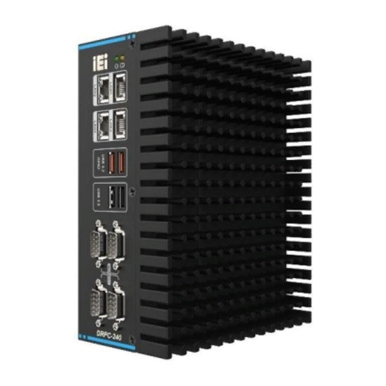
Page 14: Front Panel
DRPC-240-TGL Embedded System 1.5 Front Panel The DRPC-240-TGL front panel contains: 4 x 2.5GbE LAN 2 x USB 3.2 Gen 2 port 2 x USB 2.0 port 2 x RS-232 port 2 x RS-422/485 port Figure 1-2: DRPC-240-TGL Front Panel 1.6 Rear Panel... -
Page 15: Right Side Panel
DRPC-240-TGL Embedded System Figure 1-3: DRPC-240-TGL Rear Panel 1.7 Right Side Panel The DRPC-240-TGL right side panel contains: 1 x System fan Figure 1-4: DRPC-240-TGL Right Side Panel Page 7... -
Page 16: Dimensions
DRPC-240-TGL Embedded System 1.8 Dimensions The physical dimensions of the DRPC-240-TGL series are shown below. Figure 1-5: DRPC-240-TGL Dimensions Page 8... -
Page 17: Unpacking
DRPC-240-TGL Embedded System Chapter Unpacking Page 9... -
Page 18: Unpacking
If some of the components listed in the checklist below are missing, please do not proceed with the installation. Contact the IEI reseller or vendor you purchased the DRPC-240-TGL from or contact an IEI sales representative directly. To contact an IEI sales representative, please send an email to sales@ieiworld.com. -
Page 19: Table 2-1: Packing List
DRPC-240-TGL Embedded System Quantity Item and Part Number Image DIN rail mounting kit Screw pack Table 2-1: Packing List Page 11... -
Page 20: Installation
DRPC-240-TGL Embedded System Chapter Installation Page 12... -
Page 21: Anti-Static Precautions
Electrostatic discharge (ESD) can cause serious damage to electronic components, including the DRPC-240-TGL. Dry climates are especially susceptible to ESD. It is therefore critical that whenever the DRPC-240-TGL is accessed internally, or any other electrical component is handled, the following anti-static precautions are strictly adhered ... -
Page 22: External Device Connection
DRPC-240-TGL. 3.3 External Device Connection HDMI Display Device Connection The DRPC-240-TGL has one HDMI connector for digital display device connection. To connect a display device, follow the steps below. Step 1: Location the HDMI connector. -
Page 23: Usb Device Connection
LAN cable into the RJ-45 connector on the I/O panel. Figure 3-1: LAN Connection USB Device Connection The DRPC-240-TGL has two USB 3.2 and two USB 2.0 ports. To connect a USB device, please follow the instructions below. Step 1: Located the USB connectors. -
Page 24: Rs-232/422/485 Serial Port Connection
DRPC-240-TGL Embedded System Figure 3-2: USB Connection DB-9 RS-232/422/485 Serial Port Connection The DRPC-240-TGL has two RS-232 serial ports and two RS-422/485 serial ports. The pinouts of the serial ports are listed in Chapter 4. Figure 3-3: Serial Device Connection... -
Page 25: Atx/At Mode Selection
DRPC-240-TGL Embedded System ATX/AT Mode Selection AT and ATX power modes can both be used on the DRPC-240-TGL. The selection is made through an AT/ATX switch on the top panel as shown below. Figure 3-4: ATX/AT Mode Selection 3.4 HDD Installation... -
Page 26: System Motherboard
DRPC-240-TGL Embedded System Chapter System Motherboard Page 18... -
Page 27: Ovreview
DRPC-240-TGL Embedded System 4.1 Ovreview The connectors and jumpers of the system motherboard are listed in the following sections. Layout The following diagram shows the locations of the internal/external connectors and jumpers on the motherboard. Figure 4-1: System Motherboard (Front) -
Page 28: Internal Peripheral Connectors
DRPC-240-TGL Embedded System Figure 4-2: System Motherboard (Rear) 4.2 Internal Peripheral Connectors The table below shows a list of the connectors on the motherboard. Label Function SATA Serial ATA connectors SIM1 SIM card connector M2_A1 M.2 A key card connector M2_B1 M.2 B key card connector... -
Page 29: Sata Connector (Sata1)
DRPC-240-TGL Embedded System SATA Connector (SATA1) The DRPC-240-TGL has one SATA connector for SATA device connection. PIN NO. DESCRIPTION PIN NO. DESCRIPTION Table 4-2: SATA Connector Pinoouts (SATA1) Figure 4-3:SATA Connector SIM Card Slot (SIM1) PIN NO. DESCRIPTION SIM_VCC SIM_RST... -
Page 30: A-Key Card Slot (M2_A1)
DRPC-240-TGL Embedded System Figure 4-4: SIM Card Slot (SIM1) M.2 A-Key Card Slot (M2_A1) The M.2 A-Key card slot supports USB 2.0 and PCIe x1. PIN NO. DESCRIPTION PIN NO. DESCRIPTION +V3.3A USB+ +V3.3A USB- Module Key Module Key Module Key... -
Page 31: B-Key Card Slot (M2_B1)
DRPC-240-TGL Embedded System PCIE_RX0- CLK_PCIE0+ CLK_PCIE0- BUF_PLT_RST# PCIE_CLKREQ# 54 Pull Up +V3.3A PCIE_WAKE# Pull Up +V3.3A +V3.3A +V3.3A Table 4-4: M.2 A-Key Card Slot Pinouts (M2_A1) M.2 B-Key Card Slot (M2_B1) The M.2 B-Key card slot supports USB 3.0 and SIM card. -
Page 32: Table 4-5: M.2 B-Key Slot Pinouts (M2_B1)
DRPC-240-TGL Embedded System Module Key Module Key Module Key USB3.0_RX- UIM_RST USB3.0_RX+- UIM_CLK UIM_DATA USB3.0_TX- UIM_PWR USB3.0_TX+ SMBCLK(1.8V) PCIE_RXN0 SMBDATA(1.8V) PCIE_RXP0 PCIE_TXN0 PCIE_TXP0 PERST# PCIE_CLK# PCIE_WAKE# PCIE_CLK VCC3 VCC3 VCC3 Table 4-5: M.2 B-Key Slot Pinouts (M2_B1) Page 24... -
Page 33: Cpu Fan Connector
DRPC-240-TGL Embedded System CPU Fan Connector The CPU fan connector can provide 12V/500mA to a CPU fan. PIN NO. DESCRIPTION +V12S Rotation Signal PWM Control Signal Table 4-6: CPU Fan Connector Pinouts (CPU/FAN1) 4.3 External Peripheral Connectors The table below shows a list of the external connectors of the system. -
Page 34: Hdmi Connector (Hdmi1)
DRPC-240-TGL Embedded System HDMI Connector (HDMI1) PIN NO. DESCRIPTION PIN NO. DESCRIPTION HDMI_DATA2 HDMI_DATA2# HDMI_DATA1 HDMI_DATA1# HDMI_DATA0 HDMI_DATA0# HDMI_CLK HDMI_CLK# HDMI_SCL HDMI_SDA HDMI_HPD Table 4-7: HDMI Connector Pinouts (HDMI1) Figure 4-5: HDMI Connector DP Connector (DP1) PIN NO. DESCRIPTION PIN NO. DESCRIPTION... -
Page 35: Usb 3.2 Gen 2 Connectors (Usb2_Con1)
USB3_ RX+ USB3_TX- USB3_TX- USB3_TX+ USB3_TX+ Table 4-9: USB 3.2 Gen 2 Connector Pinouts (USB2_CON1) USB 2.0 Connectors (USB1) The DRPC-240-TGL provides two USB 2.0 connectors for USB device connection. PIN NO. DESCRIPTION PIN NO. DESCRIPTION USB_VCC USB_VCC DATA- DATA-... -
Page 36: Rs-232 Connectors (Com1/2)
DRPC-240-TGL Embedded System Figure 4-7: USB 2.0 Connector RS-232 Connectors (COM1/2) PIN NO. DESCRIPTION PIN NO. DESCRIPTION ISOCOM_GND Table 4-11: RS-232 Connector Pinouts (COM1, COM2) Figure 4-8: RS-232 Connector Page 28... -
Page 37: Rs-422/485 Serial Port Connectors (Com3/4)
Remote Power Connector (PW_BTN1) This connector is for remote power control. PIN NO. DESCRIPTION PWRBTN_SW# Table 4-13: Remote Power Connector (PW_BTN1) Dual LAN Connectors (PLAN1, PLAN2) The DRPC-240-TGL has four RJ-45 Ethernet connectors. PIN NO. DESCRIPTION PIN NO. DESCRIPTION MDIA3- MDIA1+ MDIA3+ MDIA2+-... -
Page 38: Power Input Connector (Pwr1)
DRPC-240-TGL Embedded System Figure 4-9: RJ-45 Connector Power Input Connector (PWR1) This connector supports +12V ~ +28V DC power input. PIN NO. DESCRIPTION +12V~28V +12V~28V Table 4-15: Power Input Connector Pinouts (PWR1) System Fan Connector The system fan connector can provide 12V/500mA to a system fan. -
Page 39: A Safety Precautions
DRPC-240-TGL Embedded System Appendix Safety Precautions Page 31... -
Page 40: Safety Precautions
DRPC-240-TGL Embedded System A.1 Safety Precautions WARNING: The precautions outlined in this appendix should be strictly followed. Failure to follow these precautions may result in permanent damage to the DRPC-240-TGL. Please follow the safety precautions outlined in the sections that follow: A.1.1 General Safety Precautions... -
Page 41: Anti-Static Precautions
Electrostatic discharge (ESD) can cause serious damage to electronic components, including the DRPC-240-TGL. Dry climates are especially susceptible to ESD. It is therefore critical that whenever the DRPC-240-TGL is opened and any of the electrical components are handled, the following anti-static precautions are strictly adhered to. -
Page 42: Product Disposal
DRPC-240-TGL Embedded System A.1.3 Product Disposal CAUTION: Risk of explosion if the battery is replaced by an incorrect type; Replacement of a battery with an incorrect type that can defeat a safeguard (for example, in the case of some lithium battery types);... -
Page 43: Maintenance And Cleaning Precautions
A.2 Maintenance and Cleaning Precautions When maintaining or cleaning the DRPC-240-TGL, please follow the guidelines below. A.2.1 Maintenance and Cleaning Prior to cleaning any part or component of the DRPC-240-TGL, please read the details below. The interior of the DRPC-240-TGL does not require cleaning. Keep fluids away from the DRPC-240-TGL interior. -
Page 44: B Regulatory Compliance
DRPC-240-TGL Embedded System Appendix Regulatory Compliance Page 36... - Page 45 DRPC-240-TGL Embedded System DECLARATION OF CONFORMITY This equipment is in conformity with the following EU directives: EMC Directive 2014/30/EU Low-Voltage Directive 2014/35/EU RoHS II Directive 2015/863/EU If the user modifies and/or install other devices in the equipment, the CE conformity declaration may no longer apply.
- Page 46 DRPC-240-TGL Embedded System Ελληνική [Greek] IEI Integration Corp ΔΗΛΩΝΕΙ ΟΤΙ ΕΞΟΠΛΙΣΜΟΣ ΣΥΜΜΟΡΦΩΝΕΤΑΙ ΠΡΟΣ ΤΙΣ ΟΥΣΙΩΔΕΙΣ ΑΠΑΙΤΗΣΕΙΣ ΚΑΙ ΤΙΣ ΛΟΙΠΕΣ ΣΧΕΤΙΚΕΣ ΔΙΑΤΑΞΕΙΣ ΤΗΣ ΟΔΗΓΙΑΣ 1999/5/ΕΚ. Français [French] IEI Integration Corp déclare que l'appareil est conforme aux exigences essentielles et aux autres dispositions pertinentes de la directive 1999/5/CE.
- Page 47 DRPC-240-TGL Embedded System Slovensky [Slovak] IEI Integration Corp týmto vyhlasuje, že zariadenia spĺňa základné požiadavky a všetky príslušné ustanovenia Smernice 1999/5/ES. Suomi [Finnish] IEI Integration Corp vakuut aa täten että l itteet on direktiivin 1999/5/EY oleellisten vaatimusten ja sitä koskevien direktiivin muiden ehtojen mukainen.
- Page 48 DRPC-240-TGL Embedded System FCC WARNING This equipment complies with Part 15 of the FCC Rules. Operation is subject to the following two conditions: This device may not cause harmful interference, and This device must accept any interference received, including interference that ...
-
Page 49: C Hazardous Materials Disclosure
DRPC-240-TGL Embedded System Appendix Hazardous Materials Disclosure Page 41... - Page 50 DRPC-240-TGL Embedded System The details provided in this appendix are to ensure that the product is compliant with the RoHS II Directive (2015/863/EU). The table below acknowledges the presences of small quantities of certain substances in the product, and is applicable to RoHS II Directive (2015/863/EU).
Need help?
Do you have a question about the DRPC-240-TGL and is the answer not in the manual?
Questions and answers