Sign In
Upload
Manuals
Brands
IEI Technology Manuals
Motherboard
DRPC-240-TGL
IEI Technology DRPC-240-TGL System Manuals
Manuals and User Guides for IEI Technology DRPC-240-TGL System. We have
1
IEI Technology DRPC-240-TGL System manual available for free PDF download: User Manual
IEI Technology DRPC-240-TGL User Manual (128 pages)
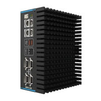
Embedded System with Intel Tiger Lake-U CPU, 8 GB DDR4 SO-DIMM, M.2 Slot, PCIe x4 Slot, RS-232, RS-422/485, HDMI, DP++ and RoHS
Brand:
IEI Technology
| Category:
Desktop
| Size: 8 MB
Table of Contents
Table of Contents
5
Introduction
11
Overview
12
Figure 1-1: DRPC-240-TGL
12
Features
13
Model Variations
13
Table 1-1: Model Description
13
Technical Specifications
14
Table 1-2: Technical Specifications
15
Front Panel
16
Rear Panel
16
Figure 1-2: DRPC-240-TGL Front Panel
16
Right Side Panel
17
Figure 1-3: DRPC-240-TGL Rear Panel
17
Figure 1-4: DRPC-240-TGL Right Side Panel
17
Dimensions
18
Figure 1-5: DRPC-240-TGL Dimensions
18
Figure 1-6: DRPC-240-TGL Dimensions
19
Unpacking
20
Unpacking
21
Packing List
21
Table 2-1: Packing List
22
Table 2-2: Optional Packing List
23
Installation
24
Anti - Static Precautions
25
Installation Precautions
25
Back Cover Removal
26
Hdd Bracket Removal
27
Figure 3-1: Removing the Back Cover
27
Figure 3-2: Removing the HDD Bracket
27
Memory Installation
28
Storage Installation
28
Figure 3-3: Memory Installation
28
SSD Installation
29
Inch SSD Installation
29
Figure 3-4: M.2 Installation
29
Wi-Fi Module Installation (Optional)
30
Figure 3-5: HDD Installation
30
Poe Power Module Installation (Optional)
31
Figure 3-6: Wi-Fi Module Installation
31
External Fan Module Installation (Optional)
32
Figure 3-7: Poe Power Module Installation
32
Adding External I/O Ports (Optional)
33
Figure 3-8: External Fan Module Installation
33
Figure 3-9: I/O Cable Installation
33
Expansion Chassis Installation (Optional)
34
Back Cover Installation
35
Figure 3-10: Expansion Chassis Installation
35
Figure 3-11 Back Cover Installation
35
External Device Connection
36
HDMI Display Device Connection
36
Ethernet Connection
36
Figure 3-12: HDMI Display Device Connection
36
Figure 3-13: LAN Connection
36
USB Device Connection
37
Figure 3-14: RJ-45 Ethernet Connector
37
Table 3-1: RJ-45 Ethernet Connector Leds
37
RS-232/422/485 Serial Port Connection
38
Figure 3-15:USB Connection
38
Table 3-2: RS-232 (COM1-2) & RS-232/422/485 (COM3-4) Connector Pinouts
38
Power Input, 3-Pin Terminal Black
39
Figure 3-16: DB-9 RS-232/422/485 Serial Port Connector
39
Figure 3-17: Serial Device Connection
39
Figure 3-18: Power Input Terminal Connection
39
ATX/AT Mode Selection
40
Remote Power Connector
40
Figure 3-19: ATX/AT Mode Selection
40
Figure 3-20: Remote Power Connector
40
Powering On/Off the System
41
Power Input & Led
41
Figure 3-21: Power Button
41
Figure 3-22: Power Input
42
Figure 3-23: Power LED
42
Table 3-3: Power LED Indicators Description
42
Available Drivers
43
Driver Download
43
Figure 3-24: IEI Resource Download Center
43
System Motherboard
45
Ovreview
46
Layout
46
Figure 4-1: System Motherboard (Front)
46
Internal Peripheral Connectors
47
Figure 4-2: System Motherboard (Rear)
47
Table 4-1: Internal Peripheral Connectors
47
SATA Connector (SATA1)
48
SIM Card Slot (SIM1)
48
Figure 4-3: SATA Connector
48
Table 4-2: SATA Connector Pinoouts (SATA1)
48
Table 4-3: SIM Card Slot Pinouts (SIM1)
48
A-Key Card Slot (M2_A1)
49
Figure 4-4: SIM Card Slot (SIM1)
49
B-Key Card Slot (M2_B1)
50
Table 4-4: M.2 A-Key Card Slot Pinouts (M2_A1)
50
Table 4-5: M.2 B-Key Slot Pinouts (M2_B1)
51
CPU Fan Connector
52
External Peripheral Connectors
52
Table 4-6: CPU Fan Connector Pinouts (CPU/FAN1)
52
Table 4-7: External Peripheral Connectors
52
HDMI Connector (HDMI1)
53
DP Connector (DP1)
53
Figure 4-5: HDMI Connector
53
Table 4-8: HDMI Connector Pinouts (HDMI1)
53
Table 4-9: DP Connector Pinouts (DP1)
53
USB 3.2 Gen 2 Connectors (USB2_CON1)
54
USB 2.0 Connectors (USB1)
54
Figure 4-6: DP Connector
54
Table 4-10: USB 3.2 Gen 2 Connector Pinouts (USB2_CON1)
54
Table 4-11: USB 2.0 Connector Pinouts (USB1)
54
Connectors (COM1/2)
55
Remote Power Connector (PW_BTN1)
55
Figure 4-7: USB 2.0 Connector
55
Figure 4-8: RS-232 Connector
55
Table 4-12: RS-232 Connector Pinouts (COM1, COM2)
55
Table 4-13: Remote Power Connector (PW_BTN1)
55
RS-422/485 Serial Port Connectors (COM3/4)
56
Dual LAN Connectors (PLAN1, PLAN2)
56
Figure 4-9: RJ-45 Connector
56
Table 4-14: RS-422/485 Serial Port Connector Pinouts (COM3, COM4)
56
Table 4-15: LAN Connector Pinouts (PLAN1, PLAN2)
56
Power Input Connector (PWR1)
57
System Fan Connector
57
Table 4-16: Power Input Connector Pinouts (PWR1)
57
Table 4-17: System Fan Connector Pinouts (FAN1)
57
A Safety Precautions
117
Safety Precautions
118
General Safety Precautions
118
Advertisement
Advertisement
Related Products
IEI Technology DRPC-230-ULT5 Series
IEI Technology DRPC-230-ULT5-i5/8G/S
IEI Technology DRPC-230-ULT5-i5/8G
IEI Technology DRPC-230-ULT5-CE/8G/S
IEI Technology DRPC-230-ULT5-C/8G/S
IEI Technology DRPC-242-ADL-P Series
IEI Technology DRPC-242-ADL-P-CCS
IEI Technology DRPC-242-ADL-P-i3CS
IEI Technology DRPC-242-ADL-P-i5CS
IEI Technology DRPC-242-ADL-P-i7CS
IEI Technology Categories
Motherboard
Touch Panel
Computer Hardware
Single board computers
Desktop
More IEI Technology Manuals
Login
Sign In
OR
Sign in with Facebook
Sign in with Google
Upload manual
Upload from disk
Upload from URL