Table of Contents
Advertisement
Quick Links
Advertisement
Table of Contents

Subscribe to Our Youtube Channel
Related Manuals for IEI Technology PPC-5xxx-9455


Summary of Contents for IEI Technology PPC-5xxx-9455
- Page 1 PPC-5xxx-9455 Panel PC Page i...
- Page 2 PPC-5xxx-9455 Panel PC Revision Date Version Changes August, 2008 1.00 Initial release Page ii...
- Page 3 PPC-5xxx-9455 Panel PC Copyright COPYRIGHT NOTICE The information in this document is subject to change without prior notice in order to improve reliability, design and function and does not represent a commitment on the part of the manufacturer. In no event will the manufacturer be liable for direct, indirect, special, incidental, or consequential damages arising out of the use or inability to use the product or documentation, even if advised of the possibility of such damages.
-
Page 4: Manual Conventions
Cautionary messages should also be heeded to help reduce the chance of losing data or damaging the PPC-5xxx-9455. Cautions are easy to recognize. The word “caution” is written as “CAUTION,” both capitalized and bold and is followed. The text is the cautionary message. - Page 5 “NOTE,” both capitalized and bold and is followed by text. The text is the cautionary message. A note message is shown below: NOTE: This is an example of a note message. Notes should always be read. Notes contain critical information about the PPC-5xxx-9455. Please take note messages seriously. Page v...
-
Page 6: Packing List
PPC-5xxx-9455 from or contact an IEI sales representative directly. To contact an IEI sales representative, please send an email to sales@iei.com.tw. The items listed below should all be included in the PPC-5xxx-9455 package. 1 x PPC-5xxx-9455 1 x Hard drive bracket... -
Page 7: Table Of Contents
PPC-5xxx-9455 Panel PC Table of Contents 1 INTRODUCTION......................1 1.1 G ....................2 ENERAL VERVIEW 1.1.1 PPC-5xxx-9455 Model Variations ..............2 1.1.2 Applications ....................... 3 1.1.3 Features ......................3 1.2 E ....................4 XTERNAL VERVIEW 1.2.1 Front Panel ......................4 1.2.2 Rear Panel ...................... - Page 8 PPC-5xxx-9455 Panel PC 2.5 S ....................22 YSTEM HIPSETS 2.5.1 Intel® 945G Northbridge Chipset ..............23 2.5.2 ICH7 Southbridge Chipset................23 2.6 G ....................24 RAPHICS UPPORT 2.6.1 Analog CRT Support ..................25 2.6.2 LVDS Support ....................25 2.7 M ........................
- Page 9 PPC-5xxx-9455 Panel PC 4.5.4 CF Card Setup (JP7)..................44 4.5.5 COM Port RI and Voltage Selection (JP3, JP4, JP5, JP6, JP8) ..... 44 4.5.6 COM5 RS-232/422/485 Settings ..............45 4.5.6.1 COM5 RS-232/422/485 RX Select (J2) ........... 45 4.5.6.2 COM5 RS-422/485 TX Select (J3)............45 4.5.6.3 COM5 D-Sub Pinout Selection (J4) ............
- Page 10 PPC-5xxx-9455 Panel PC 5.3 A ....................... 69 DVANCED 5.3.1 CPU Configuration..................71 5.3.2 IDE Configuration ................... 73 5.3.2.1 IDE Master, IDE Slave ................75 5.3.3 Floppy Configuration..................80 5.3.4 Super IO Configuration..................81 5.3.5 Hardware Health Configuration..............86 5.3.6 Power Configuration..................91 5.3.6.1 ACPI Configuration ..................
- Page 11 PPC-5xxx-9455 Panel PC 7.1 S ..............142 YSTEM AINTENANCE NTRODUCTION 7.2 M ................142 OTHERBOARD EPLACEMENT 7.3 B ..................142 OVER EMOVAL 7.4 DIMM R ................... 143 EPLACEMENT 7.5 E ................144 LEVATED LATFORM EMOVAL 7.6 PSU M ................146...
- Page 12 PPC-5xxx-9455 Panel PC HS C 2002/95/EC W ........175 OMPLIANT NDER ITHOUT ERCURY Page xii...
- Page 13 PPC-5xxx-9455 Panel PC List of Figures Figure 1-1: PPC-5xxx-9455 ......................2 Figure 1-2: Front View ........................4 Figure 1-3: PPC-5xxx-9455 Rear View ..................5 Figure 1-4: PPC-5xxx-9455 Top View....................5 Figure 1-5: Bottom View ........................6 Figure 1-6: Left View........................7 Figure 1-7: Right View ........................7 Figure 1-8: Internal Components ....................8...
- Page 14 PPC-5xxx-9455 Panel PC Figure 4-11: Optical Drive Blank Plate Assembly ..............52 Figure 4-12: Optical Drive Screws ....................53 Figure 4-13: Optical Drive SATA Cable ..................54 Figure 4-14: Optical Drive Bracket Screws ................54 Figure 4-15: Wall-mounting Bracket ...................56 Figure 4-16: Mount the Chassis ....................57 Figure 4-17: Secure the Chassis ....................58...
- Page 15 PPC-5xxx-9455 Panel PC Figure 6-23: Windows Logo Testing..................136 Figure 6-24: InstallShield Wizard Complete................136 Figure 6-25: S-Video Patch Folder ................... 137 Figure 6-26: Touch Panel Driver Welcome Screen ..............137 Figure 6-27: Touch Panel License Agreement ............... 138 Figure 6-28: Touch Panel Installation Directory..............139 Figure 6-29: Touch Panel Drivers Installing ................
- Page 16 PPC-5xxx-9455 Panel PC List of Tables Table 1-1: PPC-5xxx-9455 Model Variation ..................3 Table 2-1: PPC-5xxx-9455 Specifications ..................12 Table 2-2: Motherboard Specifications ..................13 Table 2-3: 15” TFT LCD Monitor Specifications ................14 Table 2-4: 17” TFT LCD Monitor Specifications ................15 Table 2-5: 19” TFT LCD Monitor Specifications ................16 Table 2-6: ACE-4518AP Power Supply Specifications..............17...
- Page 17 PPC-5xxx-9455 Panel PC BIOS Menus BIOS Menu 1: Main ........................68 BIOS Menu 2: Advanced ......................70 BIOS Menu 3: CPU Configuration ....................71 BIOS Menu 4: IDE Configuration....................73 BIOS Menu 5: IDE Master and IDE Slave Configuration ............75 BIOS Menu 6: IDE Master and IDE Slave Configuration ............80 BIOS Menu 7: Super IO Configuration..................81...
-
Page 19: Introduction
PPC-5xxx-9455 Panel PC Chapter Introduction Page 1... -
Page 20: General Overview
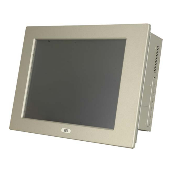
The PPC-5xxx-9455 flat panel PC is for industrial environments like production lines and machine automation. The PPC-5xxx-9455 provides all the features of a PC, combined with a touch panel screen for mouse and keyboard free data input. The PPC-5xxx-9455 provides wired and, optionally, wireless networking for integration into company networks. -
Page 21: Applications
Table 1-1: PPC-5xxx-9455 Model Variation 1.1.2 Applications The PPC-5xxx-9455 flat panel PC is designed for rigorous industrial environments where it may be exposed to both heat and moisture. Its durability and strength also makes it an ideal choice for public access computers. Some possible applications include:... -
Page 22: External Overview
GbE, USB 2.0, audio, parallel port, serial port connectors, VGA port, PCI card slot and a CompactFlash® card slot. 1.2.1 Front Panel The front panel of the PPC-5xxx-9455 (Figure 1-2) is a flat panel TFT LCD screen surrounded by an aluminum frame. Figure 1-2: Front View... -
Page 23: Rear Panel
The rear panel has a fan vent, four VESA standard mounting holes and several retention screw holes. The VESA mounting holes are circled in Figure 1-3. Figure 1-3: PPC-5xxx-9455 Rear View 1.2.3 Top Panel The top panel has two fan vents, eight mounting clamp slots and three retention screws for securing the drive bay bracket. -
Page 24: Bottom Panel
PPC-5xxx-9455 Panel PC 1.2.4 Bottom Panel The bottom panel shown in Figure 1-5 has the following interfaces: 1 x Power input connector 1 x Power switch 4 x USB connectors 1 x Reset button 2 x RJ-45 GbE connectors 1 x PS/2 mouse connector... -
Page 25: Left Panel
PPC-5xxx-9455 Panel PC 1.2.5 Left Panel The left side panel has two fan vents and four retention screws for securing the two internal fans. The retention screws are circled in Figure 1-6. Figure 1-6: Left View 1.2.6 Right Panel The right side panel provides access to a slim type CD drive bay and a FDD drive bay shown in Figure 1-7. -
Page 26: Internal Overview
PPC-5xxx-9455 Panel PC 1.3 Internal Overview The PPC-5xxx-9455 internal components are configured in three levels. The PSU cover bracket to the left (Figure 1-8) supports the hard drive and optical drive brackets. Below the PSU cover bracket is the power supply. On the same level as the power supply is the motherboard. -
Page 27: Specifications
PPC-5xxx-9455 Panel PC Chapter Specifications Page 9... -
Page 28: Introduction
2 x Cooling fans The technical specifications for these components and the system are shown in the sections below. 2.1.1 System Specifications The technical specifications for the PPC-5xxx-9455 system are listed in Table 2-1. SPECIFICATION DESCRIPTION Front Panel Aluminum Front Panel meets IP 65 standard... - Page 29 PPC-5xxx-9455 Panel PC SPECIFICATION DESCRIPTION Touch Screen Optional 5-wire resistive type touch screen with RS-232 interface Display Supports Dual Display Add-On Card (Optional) One PCI card Drive Bay One 2.5” HDD bay with anti-shock One slim type CD drive bay One slim type FDD bay One CompactFlash®...
-
Page 30: Motherboard Specifications
PPC-5170A-9455: 8 kg/12 kg PPC-5190A-9455: 12.6 kg/18.2 kg Environment RoHS Compliant Table 2-1: PPC-5xxx-9455 Specifications 2.1.2 Motherboard Specifications The PPC-5xxx-9455 comes with a POS-9455 motherboard. The technical specifications of the motherboard are listed in Table 2-2. SPECIFICATION DESCRIPTION LGA775 Intel® Core™2 Duo Pentium®... -
Page 31: Flat Panel Screen
1 x IrDA interface Table 2-2: Motherboard Specifications 2.1.3 Flat Panel Screen The PPC-5xxx-9455 comes with a flat panel TFT LCD screen. Screen specifications for each model are detailed below. 2.1.3.1 PPC-5150A-9455 Screen The PPC-5150A-9455 comes with a 15” TFT LCD monitor at the front of the flat panel PC. -
Page 32: Ppc-5170A-9455 Screen
PPC-5xxx-9455 Panel PC SPECIFICATION DETAILS 262K Number of Colors Color Saturation (%) View Angel (H/V) 120/100 Brightness (cd/m2) Contrast Ratio 400:1 Response Time (ms) (at 25°C) Power Consumption (W) 11.5 Interface 1ch LVDS Supply Voltage (V) Backlight 2 CCFL Outline Dimensions (mm) 326.5 x 253.5 x 12.0... -
Page 33: Ppc-5190A-9455 Screen
PPC-5xxx-9455 Panel PC SPECIFICATION DETAILS View Angel (H/V) 140 / 130 Brightness (cd/m2) Contrast Ratio 500 : 1 Response Time (ms) (at 25°C) 25.8 Power Consumption (W) Interface 2ch LVDS Supply Voltage (V) 4 CCFL Backlight Outline Dimensions (mm) 358.5 x 296.5 x 17.0... -
Page 34: Power Supply
Table 2-5: 19” TFT LCD Monitor Specifications 2.1.4 Power Supply The PPC-5xxx-9455 flat panel PC comes with either an ACE-4518AP 180 W AC-DC 1U, or ACE-4520C 200 W DC 1U RoHS compliant ATX power supply. The PSUs have an MTBF greater than 100,000 hours. -
Page 35: Ace-4518Ap Power Supply
PPC-5xxx-9455 Panel PC 2.1.4.1 ACE-4518AP Power Supply Specifications for the ACE-4518AP PSU module are shown in (Table 2-6). Specification Rating INPUT Voltage AC90 V ~ 265 VAC Full Range Frequency 47 ~ 63Hz Input Current 4A(RMS)@115 VAC 2A(RMS)@230 VAC Inrush Current... -
Page 36: Ace-4520C Power Supply
5 –95% RH, Non-condensing (Operating & Storage) Dimension 150 mm (W) x 81.5 mm (H) x 40.3 mm (D) Table 2-7: ACE-4520C Power Supply Specifications 2.2 Dimensions The dimensions of the PPC-5xxx-9455 are shown in the sections below. Page 18... -
Page 37: Ppc-5150A-9455 Dimensions
PPC-5xxx-9455 Panel PC 2.2.1 PPC-5150A-9455 Dimensions The dimensions of the PPC-5150A-9455 flat panel PC are shown in Figure 2-1 below. Figure 2-1: PPC-5150A-9455 Dimensions (units in mm) Page 19... -
Page 38: Ppc-5170A-9455 Dimensions
PPC-5xxx-9455 Panel PC 2.2.2 PPC-5170A-9455 Dimensions The dimensions of the PPC-5170A-9455 flat panel PC are shown in Figure 2-2 below. Figure 2-2: PPC-5170A-9455 Dimensions (units in mm) Page 20... -
Page 39: Ppc-5190A-9455 Dimensions
PPC-5xxx-9455 Panel PC 2.2.3 PPC-5190A-9455 Dimensions The dimensions of the PPC-5190A-9455 flat panel PC are shown in Figure 2-3 below. Figure 2-3: PPC-5190A-9455 Dimensions (units in mm) Page 21... -
Page 40: Motherboard
PPC-5xxx-9455 Panel PC 2.3 Motherboard The PPC-5xxx-9455 flat screen PC contains a POS-9455 motherboard. The motherboard is the heart of any computer and is responsible for transmitting, receiving and processing data as well as driving the different on-board devices. This chapter gives a brief introduction to the POS-9455 motherboard. -
Page 41: Intel® 945G Northbridge Chipset
PPC-5xxx-9455 Panel PC Specifications of these two chipsets are listed in the subsections below. 2.5.1 Intel® 945G Northbridge Chipset The Intel® 945G Northbridge chipset comes with the following features: Supports the Intel Pentium 4 processor and Intel Celeron processor with Intel NetBurst®... -
Page 42: Graphics Support
PPC-5xxx-9455 Panel PC Integrated Serial ATA Host Controllers Independent DMA operation on two ports. Data transfer rates up to 1.5 Gb/s (150 MB/s). Integrated IDE Controller Supports “Native Mode” Register and Interrupts Independent timing of up to 4 drives Ultra ATA/100/66/33, BMIDE and PIO modes... -
Page 43: Analog Crt Support
PPC-5xxx-9455 Panel PC 2.6.1 Analog CRT Support The VGA port connects a peripheral monitor to the PPC-5xxx-9455 system. A DB-15 VGA connector on the external peripheral interface connector panel is interfaced to the Intel® 945G Northbridge. The Intel® 945G supports analog CRT monitors with the following... -
Page 44: Storage
PPC-5xxx-9455 Panel PC Figure 2-5: SO-DIMM Socket 2.8 Storage There following storage options are available: CompactFlash® SATA hard drive ® 2.8.1 CompactFlash CompactFlash® socket supports standard CompactFlash® Type CompactFlash® Type II cards. The chipset flash interface is multiplexed with an IDE interface and can be connected to an array of industry standard NAND Flash or NOR Flash devices. -
Page 45: Sata Hard Drive
PPC-5xxx-9455 Panel PC Figure 2-6: CompactFlash® Slot 2.8.2 SATA Hard Drive The integrated SATA controller supports two SATA drives with independent DMA operations. One SATA port is implemented internally for the internal 2.5” SATA hard drive. The second SATA port is implemented on the external connector panel through an eSATA connector. -
Page 46: Expansion Slots
PPC-5xxx-9455 Panel PC Figure 2-7: SATA Hard Drive Slot 2.9 Expansion Slots The PPC-5xxx-9455 includes either a PCI or PCIe x4 expansion card slot. The expansion card slots add additional functionality to the PPC-5xxx-9455. Figure 2-8: Expansion Card Slot PCI cards available for the PPC-5xxx-9455 include:... -
Page 47: External Device Connectors
Firewire & USB cards 2.10 External Device Connectors The external device connectors allow external components to be attached to the PPC-5xxx-9455. The external communications device connectors are shown in the sections below. 2.10.1 USB 2.0 Ports USB connections provide fast data transmission to external devices including USB flash disks. -
Page 48: Serial Ports
PPC-5xxx-9455 Panel PC 2.10.2 Serial Ports Serial ports provide communications to external devices. Four of the external serial ports provide short-range communications, while one provides for longer range communication. Figure 2-10: Serial Ports Some features of the serial ports include:... -
Page 49: Gigabit Ethernet
Statistics for SNMP MIB II, Ethernet-like MIB, and Ethernet MIB (802.3z, clause 30) Serial EEPROM or serial flash support JTAG support 2.12 Front Panel The front panel of the PPC-5xxx-9455 consists of an LCD monitor and a touch screen panel. Page 31... -
Page 50: Flat Screen
The PPC-5xxx-9455 comes with a TFT LCD monitor. The tough construction of the TFT monitor allows the PPC-5xxx-9455 to withstand the conditions it is likely to be exposed to during regular use. Some of the specifications of the TFT monitors are shown below: Pixel pitch of 0.297 mm or less... -
Page 51: Unpacking
PPC-5xxx-9455 Panel PC Chapter Unpacking Page 33... -
Page 52: Anti-Static Precautions
PPC-5xxx-9455 and severe injury to the user. Electrostatic discharge (ESD) can cause serious damage to electronic components, including the PPC-5xxx-9455. Dry climates are especially susceptible to ESD. It is critical that the following anti-static precautions are strictly adhered to whenever handling the PPC-5xxx-9455 or any other electrical component. -
Page 53: Package Contents
If any components listed in the checklist below are missing, do not proceed with the installation. Contact the IEI reseller or vendor the PPC-5xxx-9455 was purchased from or contact an IEI sales representative directly by sending an email to sales@iei.com.tw. -
Page 54: Table 3-1: Package List Contents
PPC-5xxx-9455 Panel PC Quantity Item and Part Number Image Screw set IDE adapter (for slim CD-ROM) User manual CD and driver CD Touch pen Table 3-1: Package List Contents Page 36... -
Page 55: Installation And Configuration
PPC-5xxx-9455 Panel PC Chapter Installation and Configuration Page 37... -
Page 56: Installation Precautions
Anti-static Discharge: If a user open the rear panel of the PPC-5xxx-9455, to configure the jumpers or plug in added peripheral devices, ground themselves first and wear and anti-static wristband. -
Page 57: Installation And Configuration Steps
Set the jumper settings. Step 3: Install HDD, CompactFlash® and CD drive. Step 4: Mount the PPC-5xxx-9455 flat panel PC. Step 5: Connect peripheral devices to the bottom panel of the PPC-5xxx-9455. Step 6: Configure the system.Step 0: Page 39... -
Page 58: Remove The
PPC-5xxx-9455 Panel PC 4.4 Remove the Back Cover Remove all the retention screws on the back cover. Lift the cover up to remove (Figure 4-1). Figure 4-1: Back Cover Retention Screws Page 40... -
Page 59: Jumper Settings
PPC-5xxx-9455 Panel PC 4.5 Jumper Settings NOTE: These jumper settings and the jumper locations are described in detail in the user manual that came with the POS-9455 motherboard. Please refer to the manual for more detailed descriptions of the jumper settings. -
Page 60: At/Atx Power Selection (At_Pwr_Sw1)
Table 4-1: Onboard Jumpers 4.5.1 AT/ATX Power Selection (AT_PWR_SW1) The AT/ATX power selection switch selects AT or ATX power for the PPC-5xxx-9455. ATX power has more power saving capabilities than AT power. The AT/ATX selection jumper is connected to the AT/ATX switch on the I/O panel of the PPC-5xxx-9455. -
Page 61: Monitor Setup (Jp1)
PPC-5xxx-9455 Panel PC DESCRIPTION Normal (Default) Clear CMOS Table 4-3: Clear CMOS Jumper Settings 4.5.3 Monitor Setup (JP1) WARNING: Do not change these settings. They are set for the installed LCD panel. Using different settings on the preinstalled monitor can destroy it. -
Page 62: Cf Card Setup (Jp7)
PPC-5xxx-9455 Panel PC 4.5.4 CF Card Setup (JP7) The CF Card Setup jumper configures a CF card as either the IDE slave or IDE master. DESCRIPTION Open Slave Close Master Table 4-6: CF Card Setup Jumper Settings 4.5.5 COM Port RI and Voltage Selection (JP3, JP4, JP5, JP6, JP8) Use the COM port settings jumpers to select the voltage of serial port pin 9. -
Page 63: Com5 Rs-232/422/485 Settings
PPC-5xxx-9455 Panel PC COM4 Pin-9 Setting 12 V Table 4-10: COM4 RI and Voltage Selection Jumper COM5 Pin-9 Setting 12 V Table 4-11: COM5 RI and Voltage Selection Jumper 4.5.6 COM5 RS-232/422/485 Settings To enable RS-232, RS-422 or RS-485 on COM5, all the following jumpers should be setup. -
Page 64: Com5 D-Sub Pinout Selection (J4)
Do not change these settings. They are set for the installed LCD panel. Using different settings on the preinstalled monitor can destroy it. The LCD setup sets the voltage and default monitor settings on the PPC-5xxx-9455. LCD Voltage 3.3 V... -
Page 65: Touch Screen Selection (Jp7)
PPC-5xxx-9455 Panel PC 4.5.8 Touch Screen Selection (JP7) The touch screen selection jumper selects the type of touch screen panel connected to the system. DESCRIPTION 5-wire touch panel 2-3 closed 4-wire or 8-wire touch panel Table 4-17: Touch Screen Selection 4.6 Drive Installation... -
Page 66: Figure 4-2: Hdd Retention Screws
PPC-5xxx-9455 Panel PC Figure 4-2: HDD Retention Screws Step 3: Attach the SATA connector cable to the bracket. Figure 4-3: HDD SATA Connector Step 4: Attach the hard drive in the bracket. To do this, slide the hard drive onto the bracket until it connects with the SATA connector at the back. -
Page 67: Figure 4-4: Hdd Retention Screws
PPC-5xxx-9455 Panel PC Figure 4-4: HDD Retention Screws Step 5: Install the hard drive bracket (with hard drive and SATA cable attached) into the PPC-5xxx-9455 and fasten the four hard drive bracket screws.Step 0: Figure 4-5: HDD Retention Screws Page 49... -
Page 68: Compactflash Installation
PPC-5xxx-9455 Panel PC ® 4.6.2 CompactFlash Installation To install the CompactFlash® card, please follow the steps below: Step 1: Undo the CompactFlash® slot cover screw and remove the CompactFlash® cover plate. Figure 4-6: CompactFlash® Cover Plate Step 2: Insert the CompactFlash® card into the slot. -
Page 69: Cd Drive Installation
PPC-5xxx-9455 Panel PC Step 3: Fasten the CompactFlash® cover plate.Step 0: Figure 4-8: CompactFlash® Cover Plate 4.6.3 CD Drive Installation To install a CD drive, please follow the steps below. Step 1: Remove the back cover (Section 4.4). Step 2: Attach the CD drive adapter to the CD-ROM if it is an IDE drive (if it is a SATA drive, proceed to Step 5:). -
Page 70: Figure 4-10: Cd Drive Retention Screws
PPC-5xxx-9455 Panel PC Step 5: Undo the optical drive bracket screws and remove the optical drive bracket. Figure 4-10: CD Drive Retention Screws Step 6: Remove the four screws from the optical drive bracket assembly. Remove the blank drive plate. -
Page 71: Figure 4-12: Optical Drive Screws
PPC-5xxx-9455 Panel PC Step 7: Install the optical drive in the same position as the previously removed blank optical drive plate. Fasten the same four screws to attach the optical drive to the bracket. Figure 4-12: Optical Drive Screws Page 53... -
Page 72: Figure 4-13: Optical Drive Sata Cable
Attach the SATA cable to the back of the optical drive and fasten the SATA cable screws. Figure 4-13: Optical Drive SATA Cable Step 9: Reinstall the optical drive bracket into the PPC-5xxx-9455 and fasten the optical bracket screws.Step 0: Figure 4-14: Optical Drive Bracket Screws... -
Page 73: Mounting The System
Rack mounting The mounting methods are fully described below. 4.7.1 Wall Mounting To mount the PPC-5xxx-9455 flat panel PC onto a wall, please follow the steps below. Step 1: Select the location on the wall for the wall-mounting bracket. Step 2: Carefully mark the locations of the four bracket screw holes on the wall. -
Page 74: Figure 4-15: Wall-Mounting Bracket
PPC-5xxx-9455 Panel PC Figure 4-15: Wall-mounting Bracket Step 6: Insert the four monitor mounting screws provided in the wall mounting kit into the four screw holes on the real panel of the monitor and tighten until the screw shank is secured against the rear panel (see Figure 3-12). -
Page 75: Figure 4-16: Mount The Chassis
PPC-5xxx-9455 Panel PC Figure 4-16: Mount the Chassis Step 9: Secure the panel PC with the wall-mounting kit. To do this, stick the protective cushion to the wall-mounting kit first. Then, put the wall-mounting kit on the top panel of the panel PC. Carefully mark the location of the wall-mounting kit screw holes on the wall. -
Page 76: Panel/ Mounting
PPC-5xxx-9455 Panel PC Figure 4-17: Secure the Chassis 4.7.2 Panel/ Mounting To mount the PPC-5xxx-9455 flat panel PC into a panel, please follow the steps below. NOTE: The maximum panel thickness should be no more than 6 mm. Step 1: Select the position on the panel to mount the PPC-5xxx-9455. -
Page 77: Figure 4-18: 15" Panel Cutout Dimensions
PPC-5xxx-9455 Panel PC Figure 4-18: 15” Panel Cutout Dimensions Figure 4-19: 17” Panel Cutout Dimensions Page 59... -
Page 78: Figure 4-20: 19" Panel Cutout Dimensions
PPC-5xxx-9455 Panel PC Figure 4-20: 19” Panel Cutout Dimensions Step 3: Slide the PPC-5xxx-9455 through the hole until the metal frame is flush against the panel. Step 4: Insert the panel mounting clamps into the pre-formed holes along the edges of the PPC-5xxx-9455, behind the metal frame (Figure 4-21). -
Page 79: Rack And Cabinet Installation
(Figure 4-22). Step 0: Figure 4-22: Tighten the Panel Mounting Clamp Screws 4.7.3 Rack and Cabinet Installation To mount the PPC-5xxx-9455 into a rack/cabinet, please follow the steps below. Page 61... -
Page 80: Arm Mounting
0: 4.7.4 Arm Mounting The PPC-5xxx-9455 is VESA (Video Electronics Standards Association) compliant and can be mounted on an arm with a 100 mm interface pad. To mount the PPC-5xxx-9455 on an arm, please follow the steps below. Step 1: The arm is a separately purchased item. -
Page 81: External Peripheral Interface Connectors
Figure 4-23: Arm Mount Retention Screw Holes Step 4: Secure the PPC-5xxx-9455 to the interface pad by inserting four retention screws through the mounting arm interface pad and into the PPC-5xxx-9455 flat panel PC. Step 0: 4.8 External Peripheral Interface Connectors 4.8.1 LCD Panel Connection... -
Page 82: Usb Connection
PPC-5xxx-9455 Panel PC 4.8.3 USB Connection The external peripheral interface USB connectors provide easy and quick access to external USB devices. The external peripheral interface USB connectors are a standard connector and can easily be connected to other USB devices. -
Page 83: Bios Setup
PPC-5xxx-9455 Panel PC Chapter BIOS Setup Page 65... -
Page 84: Introduction
PPC-5xxx-9455 Panel PC 5.1 Introduction A licensed copy of AMI BIOS is preprogrammed into the ROM BIOS. The BIOS setup program allows users to modify the basic system configuration. This chapter describes how to access the BIOS setup program and the configuration options that may be changed. -
Page 85: Getting Help
PPC-5xxx-9455 Panel PC Function F1 key General help, only for Status Page Setup Menu and Option Page Setup Menu F2 /F3 key Change color from total 16 colors. F2 to select color forward. F10 key Save all the CMOS changes, only for Main Menu Table 5-1: BIOS Navigation Keys 5.1.3 Getting Help... -
Page 86: Main
PPC-5xxx-9455 Panel PC 5.2 Main The Main BIOS menu (BIOS Menu 1) appears when the BIOS Setup program is entered. The Main menu gives an overview of the basic system information. BIOS Menu 1: Main System Overview The System Overview lists a brief summary of different system components. The fields in System Overview cannot be changed. -
Page 87: Advanced
PPC-5xxx-9455 Panel PC System Memory: Displays the auto-detected system memory. Size: Lists memory size The System Overview field also has two user configurable fields: System Time [xx:xx:xx] Use the System Time option to set the system time. Manually enter the hours, minutes and seconds. -
Page 88: Bios Menu 2: Advanced
PPC-5xxx-9455 Panel PC BIOS Menu 2: Advanced Page 70... -
Page 89: Cpu Configuration
PPC-5xxx-9455 Panel PC 5.3.1 CPU Configuration Use the CPU Configuration menu (BIOS Menu 3) to view detailed CPU specifications and configure the CPU. BIOS Menu 3: CPU Configuration The CPU Configuration menu (BIOS Menu 3) lists the following CPU details:... - Page 90 PPC-5xxx-9455 Panel PC (HTT). If the operating system recognizes the installed processor, then this option should be kept in the default Disabled setting. Disabled CPUID is reported in full. EFAULT Enabled Limits the maximum CPUID to 30h. Intel® SpeedStep® Technology [Enabled] The Intel®...
-
Page 91: Ide Configuration
PPC-5xxx-9455 Panel PC 5.3.2 IDE Configuration Use the IDE Configuration menu (BIOS Menu 4) to change and/or set the configuration of the IDE devices installed in the system. BIOS Menu 4: IDE Configuration ATA/IDE Configurations [Enhanced] Use the ATA/IDE Configurations option to configure the ATA/IDE controller. - Page 92 PPC-5xxx-9455 Panel PC Enhanced Configures the on-board ATA/IDE controller to be in EFAULT Enhanced mode. In this mode, IDE channels and SATA channels are separated. Some legacy OS do not support this mode. Configure SATA as [IDE] The “Configure SATA as” option sets the configuration of the SATA ports.
-
Page 93: Ide Master, Ide Slave
PPC-5xxx-9455 Panel PC Primary IDE Master Primary IDE Slave The IDE Configuration menu (BIOS Menu 4) allows changes to the configurations for the IDE devices installed in the system. If an IDE device is detected, and one of the above listed four BIOS configuration options are selected, the IDE configuration options shown in Section 5.3.2.1 appear. - Page 94 PPC-5xxx-9455 Panel PC Device: Lists the device type (e.g. hard disk, CD-ROM etc.) Type: Indicates the type of devices a user can manually select Vendor: Lists the device manufacturer Size: List the storage capacity of the device. LBA Mode: Indicates whether the LBA (Logical Block Addressing) is a method of addressing data on a disk drive is supported or not.
- Page 95 PPC-5xxx-9455 Panel PC ARMD This option specifies an ATAPI Removable Media Device. These include, but are not limited to: LS-120 LBA/Large Mode [Auto] Use the LBA/Large Mode option to disable or enable BIOS to auto detects LBA (Logical Block Addressing). LBA is a method of addressing data on a disk drive. In LBA mode, the maximum drive capacity is 137 GB.
- Page 96 PPC-5xxx-9455 Panel PC Auto BIOS auto detects the PIO mode. Use this value if the IDE disk EFAULT drive support cannot be determined. PIO mode 0 selected with a maximum transfer rate of 3.3 MB/s PIO mode 1 selected with a maximum transfer rate of 5.2 MB/s PIO mode 2 selected with a maximum transfer rate of 8.3 MB/s...
- Page 97 PPC-5xxx-9455 Panel PC UDMA1 Ultra DMA mode 1 selected with a maximum data transfer rate of 25 MB/s Ultra DMA mode 2 selected with a maximum data transfer UDMA2 rate of 33.3 MB/s UDMA3 Ultra DMA mode 3 selected with a maximum data transfer rate of 44 MB/s (To use this mode, it is required that an 80-conductor ATA cable is used.)
-
Page 98: Floppy Configuration
PPC-5xxx-9455 Panel PC 5.3.3 Floppy Configuration Use the Floppy Configuration menu (BIOS Menu 6) to configure the floppy disk drive connected to the system. BIOS Menu 6: IDE Master and IDE Slave Configuration Floppy A/B Use the Floppy A/B option to configure the floppy disk drive. Options are listed below: Disabled 360 KB 51/4”... -
Page 99: Super Io Configuration
PPC-5xxx-9455 Panel PC 5.3.4 Super IO Configuration Use the Super IO Configuration menu (BIOS Menu 7) to set or change the configurations for the FDD controllers, parallel ports and serial ports. BIOS Menu 7: Super IO Configuration Digital I/O Address [2D8] Use the Digital I/O Address option to select the digital I/O port base address. - Page 100 PPC-5xxx-9455 Panel PC Disabled No base address is assigned to Serial Port 1 Serial Port 1 I/O port address is 3F8 and the interrupt 3F8/IRQ4 EFAULT address is IRQ4 3E8/IRQ4 Serial Port 1 I/O port address is 3E8 and the interrupt...
- Page 101 PPC-5xxx-9455 Panel PC IrDA Serial Port 2 mode is IrDA Serial Port 2 mode is ASK IR ASK IR Parallel Port Address [Disabled] Use the Parallel Port Address option to select the parallel port base address. Disabled No base address is assigned to the Parallel Port...
- Page 102 PPC-5xxx-9455 Panel PC ECP+EPP The parallel port operates in the extended capabilities port (ECP) mode. The ECP mode supports bi-directional communication between the system and the parallel port device and the transmission rates between the two are much faster than the Normal mode...
- Page 103 PPC-5xxx-9455 Panel PC Serial Port5 Address [2F0] Use the Serial Port5 IRQ option to select the interrupt address for serial port 5. No base address is assigned to serial port 5 Disabled Serial port 5 I/O port address is 3E8...
-
Page 104: Hardware Health Configuration
PPC-5xxx-9455 Panel PC 5.3.5 Hardware Health Configuration The Hardware Health Configuration menu (BIOS Menu 8) shows the operating temperature, fan speeds and system voltages. BIOS Menu 8: Hardware Health Configuration Page 86... - Page 105 PPC-5xxx-9455 Panel PC CPU FAN 1 Mode Setting [Full On Mode] Use the CPU FAN 1 Mode Setting option to configure the CPU fan. Fan is on all the time Full On Mode EFAULT FAN x Mode Setting [Automatic Mode] Use the FAN x Mode Setting option to configure the second fan.
- Page 106 PPC-5xxx-9455 Panel PC The CPU Temp. Limit of OFF option can only be set if the FAN x Mode Setting option is set to Automatic Mode. Use the CPU Temp. Limit of OFF option to select the CPU temperature at which the cooling fan should automatically turn off. To select a value, select the CPU Temp.
- Page 107 PPC-5xxx-9455 Panel PC The Temperature Limit of Full option can only be set if the FAN x Mode Setting option is set to Automatic Mode. Use the Temperature Limit of Full option to select the CPU temperature at which the cooling will reach full speed. To select a value, select the Temperature Limit of Full option and enter a decimal number between 000 and 127.
- Page 108 PPC-5xxx-9455 Panel PC The following system parameters and values are shown. The system parameters that are monitored are: System Temperatures: The following system temperatures are monitored CPU Temperature System Temperature 1 System Temperature 2 Fan Speeds: The CPU cooling fan speed is monitored.
-
Page 109: Power Configuration
PPC-5xxx-9455 Panel PC 5.3.6 Power Configuration The power configuration menu (BIOS Menu 9) sets the power features options. BIOS Menu 9: ACPI Configuration Power Supply Mode [ATX] Use the Power Supply Mode BIOS option to select the power supply that is connected to the system. -
Page 110: Acpi Configuration
PPC-5xxx-9455 Panel PC 5.3.6.1 ACPI Configuration The ACPI Configuration menu (BIOS Menu 10) configures the Advanced Configuration and Power Interface (ACPI) and Power Management (APM) options. BIOS Menu 10: ACPI Configuration Suspend Mode [S3(STR)] Use the Suspend Mode option to specify the sleep state the system enters when it is not being used. -
Page 111: Apm Configuration
PPC-5xxx-9455 Panel PC 5.3.6.2 APM Configuration The APM Configuration menu (BIOS Menu 11) allows the advanced power management options to be configured. BIOS Menu 11:Advanced Power Management Configuration Power Button Mode [On/Off] Use the Power Button Mode BIOS to specify how the power button functions. - Page 112 PPC-5xxx-9455 Panel PC Power Off The system remains turned off The system turns on Power On Last State The system returns to its previous state. If it was on, it EFAULT turns itself on. If it was off, it remains off.
- Page 113 PPC-5xxx-9455 Panel PC Resume On RTC Alarm [Disabled] Use the Resume On RTC Alarm option to specify the time the system should be roused from a suspended state. Disabled The real time clock (RTC) cannot generate a wake EFAULT event...
-
Page 114: Remote Access Configuration
PPC-5xxx-9455 Panel PC 5.3.7 Remote Access Configuration Use the Remote Access Configuration menu (BIOS Menu 12) to configure remote access parameters. The Remote Access Configuration is an AMIBIOS feature and allows a remote host running a terminal program to display and configure the BIOS settings. - Page 115 PPC-5xxx-9455 Panel PC Enabled Remote access configuration options shown below appear: Serial Port Number Serial Port Mode Flow Control Redirection after BIOS POST Terminal Type VT-UTF8 Combo Key Support These configuration options are discussed below. Serial Port Number [COM1] Use the Serial Port Number option allows to select the serial port used for remote access.
- Page 116 PPC-5xxx-9455 Panel PC NOTE: Identical baud rate setting musts be set on the host (a management computer running a terminal software) and the slave Redirection After BIOS POST [Always] Use the Redirection After BIOS POST option to specify when console redirection should occur.
-
Page 117: Usb Configuration
PPC-5xxx-9455 Panel PC 5.3.8 USB Configuration Use the USB Configuration menu (BIOS Menu 13) to read USB configuration information and configure the USB settings. BIOS Menu 13: USB Configuration USB Configuration The USB Configuration field shows the system USB configuration. The items listed are: Module Version: x.xxxxx.xxxxx... - Page 118 PPC-5xxx-9455 Panel PC Disabled USB function support disabled USB function support enabled Enabled EFAULT USB 2.0 Controller [Enabled] Use the USB 2.0 Controller BIOS option to enable or disable the USB 2.0 controller Disabled USB 2.0 controller disabled Enabled USB 2.0 controller enabled...
-
Page 119: Usb Mass Storage Device Configuration
PPC-5xxx-9455 Panel PC 5.3.8.1 USB Mass Storage Device Configuration Use the USB Mass Storage Device Configuration menu (BIOS Menu 14) to configure USB mass storage class devices. BIOS Menu 14: USB Mass Storage Device Configuration USB Mass Storage Reset Delay [20 Sec] Use the USB Mass Storage Reset Delay option to set the number of seconds POST waits for the USB mass storage device after the start unit command. - Page 120 PPC-5xxx-9455 Panel PC 40 Sec POST waits 40 seconds for the USB mass storage device after the start unit command. Device ## The Device## field lists the USB devices that are connected to the system. Emulation Type [Auto] Use the Emulation Type BIOS option to specify the type of emulation BIOS has to provide for the USB device.
-
Page 121: Pci/Pnp
PPC-5xxx-9455 Panel PC CDROM Assumes the CD-ROM is formatted as bootable media. All the devices that support block sizes greater than 512 bytes can only be booted using this option. 5.4 PCI/PnP Use the PCI/PnP menu (BIOS Menu 15) to configure advanced PCI and PnP settings. - Page 122 PPC-5xxx-9455 Panel PC IRQ# [Available] Use the IRQ# address to specify what IRQs can be assigned to a particular peripheral device. Available The specified IRQ is available to be used by EFAULT PCI/PnP devices The specified IRQ is reserved for use by Legacy ISA...
-
Page 123: Boot
PPC-5xxx-9455 Panel PC DM Channel 5 DM Channel 6 DM Channel 7 Reserved Memory Size [Disabled] Use the Reserved Memory Size BIOS option to specify the amount of memory that should be reserved for legacy ISA devices. Disabled No memory block reserved for legacy ISA devices... -
Page 124: Boot Settings Configuration
PPC-5xxx-9455 Panel PC 5.5.1 Boot Settings Configuration Use the Boot Settings Configuration menu (BIOS Menu 17) to configure advanced system boot options. BIOS Menu 17: Boot Settings Configuration Quick Boot [Enabled] Use the Quick Boot BIOS option to make the computer speed up the boot process. - Page 125 PPC-5xxx-9455 Panel PC Enabled OEM Logo displayed instead of POST messages EFAULT AddOn ROM Display Mode [Force BIOS] Use the AddOn ROM Display Mode option to allow add-on ROM (read-only memory) messages to be displayed. The system forces third party BIOS to display...
-
Page 126: Boot Device Priority
PPC-5xxx-9455 Panel PC Enabled Can be booted from a remote system through the EFAULT 5.5.2 Boot Device Priority Use the Boot Device Priority menu (BIOS Menu 18) to specify the boot sequence from the available devices. Possible boot devices may include:... -
Page 127: Bios Menu 19: Hard Disk Drives
PPC-5xxx-9455 Panel PC 3rd Drive [HDD: SM-(part number)] 4th Drive [HDD: SM-(part number)] NOTE: Only the drives connected to the system are shown. For example, if only two HDDs are connected only “1st Drive” and “2nd Drive” are listed. The boot sequence from the available devices is selected. If the “1st Drive” option is selected a list of available HDDs is shown. -
Page 128: Cd/Dvd Drives
PPC-5xxx-9455 Panel PC 5.5.4 CD/DVD Drives Use the CD/DVD Drives menu to specify the boot sequence of the available CD/DVD drives. When the menu is opened, the CD drives and DVD drives connected to the system are listed as shown below:... -
Page 129: Bios Menu 20: Cd/Dvd Drives
PPC-5xxx-9455 Panel PC BIOS Menu 20: CD/DVD Drives Page 111... -
Page 130: Security
PPC-5xxx-9455 Panel PC 5.6 Security Use the Security menu (BIOS Menu 21) to set system and user passwords. BIOS Menu 21: Security Change Supervisor Password Use the Change Supervisor Password to set or change a supervisor password. The default for this option is Not Installed. If a supervisor password must be installed, select this field and enter the password. -
Page 131: Chipset
PPC-5xxx-9455 Panel PC 5.7 Chipset Use the Chipset menu (BIOS Menu 22) to access the Northbridge and Southbridge configuration menus WARNING! Setting the wrong values for the Chipset BIOS selections in the Chipset BIOS menu may cause the system to malfunction. -
Page 132: Northbridge Configuration
PPC-5xxx-9455 Panel PC 5.7.1 Northbridge Configuration Use the Northbridge Configuration menu (BIOS Menu 22) to configure the Northbridge chipset. BIOS Menu 23:Northbridge Chipset Configuration Memory Hole [Disabled] Use the Memory Hole option to reserve memory space between 15 MB and 16 MB for ISA expansion cards that require a specified area of memory to work properly. - Page 133 PPC-5xxx-9455 Panel PC Boot Display Device Use the Boot Display Device option to select the display device used by the system when it boots. Configuration options are listed below. Auto CRT - Default CRT + LFP Flat Panel Type [By Jumper] Use the Flat Panel Type is set using the onboard jumper settings.
-
Page 134: Southbridge Configuration
PPC-5xxx-9455 Panel PC 5.7.2 Southbridge Configuration The Southbridge Configuration menu (BIOS Menu 24) allows the Southbridge chipset to be configured. BIOS Menu 24:Southbridge Chipset Configuration Spectrum [Disabled] Use the Spectrum option to reduce the EMI. Excess EMI is generated when the system clock generator pulses have extreme values. -
Page 135: Exit
PPC-5xxx-9455 Panel PC Audio Controller [Azalia] Use the Audio Controller Selection option to enable or disable the High Definition Audio CODEC. Disabled The onboard HD Audio is disabled The onboard HD Audio is enabled Azalia EFAULT 5.8 Exit Use the Exit menu (BIOS Menu 25) to load default BIOS values, optimal failsafe values and to save configuration changes. - Page 136 PPC-5xxx-9455 Panel PC Discard Changes and Exit Use the Discard Changes and Exit option to exit the BIOS configuration setup program without saving the changes made to the system. Discard Changes Use the Discard Changes option to discard the changes and remain in the BIOS configuration setup program.
-
Page 137: Software Installation
PPC-5xxx-9455 Panel PC Chapter Software Installation Page 119... -
Page 138: Available Software Drivers
PPC-5xxx-9455 Panel PC 6.1 Available Software Drivers NOTE: The content of the CD may vary throughout the life cycle of the product and is subject to change without prior notice. You may visit the IEI website or contact technical support for the latest updates. -
Page 139: Figure 6-1: Chipset Driver Installation Program
PPC-5xxx-9455 Panel PC Figure 6-1: Chipset Driver Installation Program Step 2: Double-click the infinst_Autol.exe icon. Step 3: The welcome screen in Figure 6-2 appears. Figure 6-2: Chipset Driver Installation Welcome Screen Step 4: Click N to continue the installation process. -
Page 140: Figure 6-3: Chipset Driver Installation License Agreement
PPC-5xxx-9455 Panel PC Figure 6-3: Chipset Driver Installation License Agreement Step 6: Read the license agreement. To accept the terms and conditions stipulated in the agreement, click Y Step 7: The Readme file in Figure 6-4 appears. Figure 6-4: Chipset Driver Readme File Information... -
Page 141: Figure 6-5: Chipset Driver Installation Complete
PPC-5xxx-9455 Panel PC Step 8: Read the Readme file information and then click N to start the driver installation. Step 9: The Setup Progress windows appears (Figure 6-5). Figure 6-5: Chipset Driver Installation Complete Step 10: After the driver installation process is complete click N... -
Page 142: Graphics Driver
PPC-5xxx-9455 Panel PC Figure 6-6: Chipset Driver Installation Complete Step 12: The computer must be restarted for changes to take effect. Select “Yes, I want to restart this computer now,” to restart the computer when finished, or “No, I will restart this computer later,” to manually restart the computer later. Click to complete the driver installation. -
Page 143: Figure 6-7: Graphics Setup Icon
PPC-5xxx-9455 Panel PC Figure 6-7: Graphics Setup Icon Step 2: Double-click the setup icon to start the graphics driver installation (Figure 6-7). Step 3: A new window appears with a detailed explanation of what is contained in the graphics driver file (Figure 6-8). -
Page 144: Figure 6-9: Graphics Driver Installation
PPC-5xxx-9455 Panel PC Step 5: The Graphics driver welcome screen appears (Figure 6-9). Figure 6-9: Graphics Driver Installation Step 6: Click N to continue the driver installation (Figure 6-9). Step 7: The license agreement appears (Figure 6-10). Figure 6-10: Graphics Driver License Agreement... -
Page 145: Figure 6-11: Graphics Driver Readme File
PPC-5xxx-9455 Panel PC Step 8: Read the license agreement carefully. Click Y to accept the terms of the license agreement and continue installation. Step 9: A new window appears with details of the drivers to be installed (Figure 6-11). Figure 6-11: Graphics Driver Readme file... -
Page 146: Figure 6-12: Graphics Driver Installation Notice
PPC-5xxx-9455 Panel PC Step 11: The driver installation progress window appears and shows details for each of the drivers as they are installed (Figure 6-12). Figure 6-12: Graphics Driver Installation Notice Step 12: The Setup is Complete window appears. (Figure 6-13). -
Page 147: Gigabit Ethernet Driver Installation
6.4 Gigabit Ethernet Driver Installation NOTE: Two different Gigabit Ethernet driver versions are included. These versions correspond to two releases of the PPC-5xxx-9455. Windows will automatically select the correct one. The motherboard versions and corresponding drivers are listed below POS-9455-R10 – use E172 driver POS-9455-R11 –... -
Page 148: Figure 6-14: Windows Control Panel
PPC-5xxx-9455 Panel PC Figure 6-14: Windows Control Panel Step 2: Double-click the System icon (Figure 6-15). Figure 6-15: System Icon Page 130... -
Page 149: Figure 6-16: Device Manager Tab
PPC-5xxx-9455 Panel PC Step 3: Select the Hardware tab and click the D tab (Figure 6-16). EVICE ANAGER Figure 6-16: Device Manager Tab Page 131... -
Page 150: Figure 6-17: Device Manager List
PPC-5xxx-9455 Panel PC Step 4: Right-click the “Ethernet Controller” and select “Update Driver…” to start the driver update process (Figure 6-17). Figure 6-17: Device Manager List Step 5: The Device Driver Wizard appears (Figure 6-18). Figure 6-18: Search Windows Update Prompt... -
Page 151: Figure 6-19: Search Windows Update Prompt
PPC-5xxx-9455 Panel PC Step 6: Select “No, not this time” to force the wizard to search hard drives, CD drives and floppy drives for a driver and not connect to the Internet to search for the appropriate driver (Figure 6-18). -
Page 152: Audio Driver
PPC-5xxx-9455 Panel PC Step 9: After the installation wizard finds the Gigabit Ethernet driver, the Hardware Update Completed window appears (Figure 6-20). Figure 6-20: Hardware Installation Complete Step 10: Click F to exit the installation wizard and complete the installation process.S t e p 0 :... -
Page 153: Figure 6-21: Select The Audio Codec
PPC-5xxx-9455 Panel PC Step 1: Browse to the AUDIO folder on the installation CD (Figure 6-21). Figure 6-21: Select the Audio CODEC Step 2: Double-click the Setup icon. The audio setup window appears (Figure 6-22). Step 3: Figure 6-22: Audio Driver Installation... -
Page 154: Figure 6-23: Windows Logo Testing
PPC-5xxx-9455 Panel PC Step 6: The Windows logo testing warning screen is shown. The warning explains that the software has not passed Windows logo testing. Click C ONTINUE NYWAY continue installing the audio drivers (Figure 6-23). Figure 6-23: Windows Logo Testing Step 7: The confirmation screen offers the option of restarting the computer now or later. -
Page 155: Touch Panel Driver
PPC-5xxx-9455 Panel PC 6.6 Touch Panel Driver To install the touch panel driver, please follow the steps below. Step 1: Browse to the Touch directory on the installation CD (Figure 6-25). Figure 6-25: S-Video Patch Folder Step 2: Double-click the setup icon (Figure 6-25). -
Page 156: Figure 6-27: Touch Panel License Agreement
PPC-5xxx-9455 Panel PC Step 4: Click N to begin the touch panel driver installation process (Figure 6-26). Step 5: The license agreement window appears (Figure 6-27). Figure 6-27: Touch Panel License Agreement Step 6: Read the license agreement carefully. Click I A... -
Page 157: Figure 6-28: Touch Panel Installation Directory
PPC-5xxx-9455 Panel PC Figure 6-28: Touch Panel Installation Directory Step 8: Accept the default installation directory (only change if necessary) then click to install the touch panel drivers (Figure 6-28). NSTALL Step 9: The touch panel driver begins installing (Figure 6-29). -
Page 158: Figure 6-30: Windows Logo Testing
PPC-5xxx-9455 Panel PC Figure 6-30: Windows Logo Testing Step 11: The InstallShield Wizard Completed window appears (Figure 6-31). Figure 6-31: InstallShield Wizard Complete Step 12: Click F to complete the installation process and exit the touch panel driver INISH installation program (Figure 6-31). -
Page 159: System Maintenance
PPC-5xxx-9455 Panel PC Chapter System Maintenance Page 141... -
Page 160: System Maintenance Introduction
IEI sales person directly. 7.3 Back Cover Removal WARNING! Before removing the back cover, make sure all power to the system has been disconnected. Failing to do so may cause severe damage to the PPC-5xxx-9455 and injury to the user. Page 142... -
Page 161: Dimm Replacement
PPC-5xxx-9455 Panel PC WARNING! Please take antistatic precautions when working with the internal components. The interior of the PPC-5xxx-9455 contains very sensitive electronic components. These components are easily damaged by electrostatic discharge (ESD). Before working with the internal components, make sure all anti-static precautions described earlier have been observed. -
Page 162: Elevated Platform Removal
PPC-5xxx-9455 Panel PC Figure 7-1: DIMM Socket Clip Locations Step 3: Push the new DIMM module until it engages and the white plastic end clips click into place. Make sure the end clips are fully secured after installation. Step 0: 7.5 Elevated Platform Removal... -
Page 163: Figure 7-3: Side Panel Elevated Platform Screws
PPC-5xxx-9455 Panel PC Step 2: Unfasten the elevated platform screws on the side panel (Figure 7-3). Figure 7-3: Side Panel Elevated Platform Screws Step 3: Unfasten the elevated platform screws on the bottom panel (Figure 7-4). Figure 7-4: Bottom Panel Elevated Platform Screws... -
Page 164: Psu Module Replacement
PPC-5xxx-9455 Panel PC Step 4: Unfasten the internal elevated platform screws (Figure 7-5). Figure 7-5: Internal Elevated Platform Screws Step 5: Slide the elevated platform out of the chassis. Step 0: 7.6 PSU Module Replacement Please read the warnings at the beginning of Section 4.3 before attempting to access any PPC-5xxx-9455 internal components. -
Page 165: Figure 7-6: Psu Power Cables
PPC-5xxx-9455 Panel PC Step 3: Disconnect all PSU connections including those to the motherboard (Figure 7-6) and any disk drives. Figure 7-6: PSU Power Cables Step 4: Unfasten the screws on the inside panel (Figure 7-7). Figure 7-7: PSU Bottom Panel Retention Screws... -
Page 166: Install The New Psu
PPC-5xxx-9455 Panel PC Step 5: Remove the retention screws that connect the PSU bracket to the chassis (Figure 7-8). Figure 7-8: PSU Rear Panel Screws Step 6: Remove the retention screws that connect the PSU to the PSU bracket.Step 0: 7.6.2 Install the New PSU... -
Page 167: System Cooling Fan Replacement
PPC-5xxx-9455 Panel PC 7.7 System Cooling Fan Replacement If the system cooling fans have been damaged, they must be replaced. To replace the system cooling fans, please follow the steps below. 7.7.1 Remove the Old System Cooling Fans Step 1: Remove the back cover (Section 4.4). -
Page 168: Install The New System Cooling Fans
PPC-5xxx-9455 Panel PC Step 4: Remove the system cooling fans retention screws from the left panel (Figure 7-10). Figure 7-10: System Cooling Fans Left Panel Retention Screws Step 5: Remove the system cooling fans from the chassis. Step 0: 7.7.2 Install the New System Cooling Fans To install the new system cooling fans, please follow the steps below. -
Page 169: Abios Options
PPC-5xxx-9455 Panel PC Appendix BIOS Options Page 151... - Page 170 PPC-5xxx-9455 Panel PC Below is a list of BIOS configuration options in the BIOS chapter. System Overview .........................68 System Time [xx:xx:xx] .......................69 System Date [xx/xx/xx] ......................69 Max CPUID Value Limit [Disabled] ..................71 Intel® SpeedStep® Technology [Enabled]................72 ATA/IDE Configurations [Enhanced] .................73 Configure SATA as [IDE].....................74...
- Page 171 PPC-5xxx-9455 Panel PC FAN x Mode Setting [Automatic Mode] ................87 Temperature Limit of OFF [025] ..................87 Temperature Limit of Start [025] ..................88 Temperature Limit of Full [080] ..................88 Fan Start PWM [070] ......................89 Slope PWM [4 PWM] ......................89 Power Supply Mode [ATX] ....................91 Suspend Mode [S3(STR)] ....................92...
- Page 172 PPC-5xxx-9455 Panel PC Boot From LAN Support [Disabled] ................107 Change Supervisor Password ..................112 Change User Password....................112 Memory Hole [Disabled] ....................114 Boot Display Device ......................115 Flat Panel Type [By Jumper].................... 115 PID Current Jumper Setting [1-1024x768x24] ..............115 Internal Graphics Mode Select [Enable, 8 MB] ..............
-
Page 173: B Terminology
PPC-5xxx-9455 Panel PC Appendix Terminology Page 155... - Page 174 PPC-5xxx-9455 Panel PC AC ’97 Audio Codec 97 (AC’97) refers to a codec standard developed by Intel® in 1997. ACPI Advanced Configuration and Power Interface (ACPI) is an OS-directed configuration, power management, and thermal management interface. AHCI Advanced Host Controller Interface (AHCI) is a SATA Host controller register-level interface.
- Page 175 PPC-5xxx-9455 Panel PC Direct Memory Access (DMA) enables some peripheral devices to bypass the system processor and communicate directly with the system memory. DIMM Dual Inline Memory Modules are a type of RAM that offer a 64-bit data bus and have separate electrical contacts on each side of the module.
- Page 176 PPC-5xxx-9455 Panel PC Liquid crystal display (LCD) is a flat, low-power display device that consists of two polarizing plates with a liquid crystal panel in between. LVDS Low-voltage differential signaling (LVDS) is a dual-wire, high-speed differential electrical signaling system commonly used to connect LCD displays to a computer.
-
Page 177: C Digital I/O Interface
PPC-5xxx-9455 Panel PC Appendix Digital I/O Interface Page 159... -
Page 178: Introduction
PPC-5xxx-9455 Panel PC C.1 Introduction The DIO connector on the PPC-5xxx-9455 is interfaced to GPIO ports on the Super I/O chipset. The DIO has both 4-bit digital inputs and 4-bit digital outputs. The digital inputs and digital outputs are generally control signals that control the on/off circuit of external devices or TTL devices. -
Page 179: Assembly Language Samples
PPC-5xxx-9455 Panel PC C.3 Assembly Language Samples C.3.1 Enable the DIO Input Function The BIOS interrupt call INT 15H controls the digital I/O. An assembly program to enable digital I/O input functions is listed below. Sets the digital port as input... -
Page 180: D Watchdog Timer
PPC-5xxx-9455 Panel PC Appendix Watchdog Timer Page 162... - Page 181 PPC-5xxx-9455 Panel PC NOTE: The following discussion applies to DOS environment. IEI support is contacted or the IEI website visited for specific drivers for more sophisticated operating systems, e.g., Windows and Linux. The Watchdog Timer is provided to ensure that standalone systems can always recover from catastrophic conditions that cause the CPU to crash.
- Page 182 PPC-5xxx-9455 Panel PC NOTE: When exiting a program it is necessary to disable the Watchdog Timer, otherwise the system resets. EXAMPLE PROGRAM: ; INITIAL TIMER PERIOD COUNTER W_LOOP: AX, 6F02H ;setting the time-out value BL, 30 ;time-out value is 48 seconds ;...
-
Page 183: E Address Mapping
PPC-5xxx-9455 Panel PC Appendix Address Mapping Page 165... -
Page 184: Direct Memory Access (Dma)
PPC-5xxx-9455 Panel PC E.1 Direct Memory Access (DMA) Figure E-1: Direct Memory Access (DMA) Page 166... -
Page 185: Input/Output (Io)
PPC-5xxx-9455 Panel PC E.2 Input/Output (IO) Figure E-2: Input/Output (IO) (1 of 2) Page 167... - Page 186 PPC-5xxx-9455 Panel PC Figure E-3: Input/Output (IO) (2 of 2) Page 168...
-
Page 187: Interrupt Request (Irq)
PPC-5xxx-9455 Panel PC E.3 Interrupt Request (IRQ) Figure E-4: Interrupt Request (IRQ) Page 169... -
Page 188: Memory
PPC-5xxx-9455 Panel PC E.4 Memory Figure E-5: Memory Page 170... -
Page 189: F Compatibility
PPC-5xxx-9455 Panel PC Appendix Compatibility Page 171... -
Page 190: Compatible Operating Systems
The compatible items described here have been tested by the IEI R&D team and found to be compatible with the PPC-5xxx-9455 F.1 Compatible Operating Systems The following operating systems have been successfully run on the PPC-5xxx-9455. MS-DOS 6.22 Microsoft Windows XP (32-bit) Microsoft Windows 2000 Red Hat 9.0... -
Page 191: Compatible Memory Modules
The memory modules listed below have been tested on the PPC-5xxx-9455 other memory modules that comply with the specifications may also work on the PPC-5xxx-9455 but have not been tested. The following memory modules have been successfully tested on the PPC-5xxx-9455. -
Page 192: G Hazardous Materials Disclosure
PPC-5xxx-9455 Panel PC Appendix Hazardous Materials Disclosure Page 174... -
Page 193: Hazardous Materials Disclosure Table For Ipb Products Certified As
PPC-5xxx-9455 Panel PC G.1 Hazardous Materials Disclosure Table for IPB Products Certified as RoHS Compliant Under 2002/95/EC Without Mercury The details provided in this appendix are to ensure that the product is compliant with the Peoples Republic of China (China) RoHS standards. The table below acknowledges the presences of small quantities of certain materials in the product, and is applicable to China RoHS only. - Page 194 PPC-5xxx-9455 Panel PC Part Name Toxic or Hazardous Substances and Elements Lead Mercury Cadmium Hexavalent Polybrominated Polybrominated Biphenyls Diphenyl (Pb) (Hg) (Cd) Chromium (CR(VI)) (PBB) Ethers (PBDE) Housing Display Printed Circuit Board Metal Fasteners Cable Assembly Fan Assembly Power Supply...
- Page 195 PPC-5xxx-9455 Panel PC 此附件旨在确保本产品符合中国 RoHS 标准。以下表格标示此产品中某有毒物质的含量符 合中国 RoHS 标准规定的限量要求。 本产品上会附有”环境友好使用期限”的标签,此期限是估算这些物质”不会有泄漏或突变”的 年限。本产品可能包含有较短的环境友好使用期限的可替换元件,像是电池或灯管,这些元 件将会单独标示出来。 部件名称 有毒有害物质或元素 铅 汞 镉 六价铬 多溴联苯 多溴二苯 醚 (Pb) (Hg) (Cd) (CR(VI)) (PBB) (PBDE) 壳体 显示 印刷电路板 金属螺帽 电缆组装 风扇组装 电力供应组装 电池 O: 表示该有毒有害物质在该部件所有物质材料中的含量均在 SJ/T11363-2006 标准规定的限量要求以下。 X: 表示该有毒有害物质至少在该部件的某一均质材料中的含量超出 SJ/T11363-2006 标准规定的限量要求。...
- Page 196 PPC-5xxx-9455 Panel PC Index Page 178...
- Page 197 PPC-5xxx-9455 Panel PC DIMM Replacement ........ 143 Drivers Broadcom GbE LAN ......129 ACPI ............92 ® Intel Chipset ........120 anti-static precautions........34 ® Intel Graphics Media Accelerator..124 anti-static pad ........34 Realtek AC`97 Audio - ALC665 ..134 anti-static wristband.......34 S-Video Patch........
- Page 198 PPC-5xxx-9455 Panel PC Keyboard and Mouse Connection .....64 Safety Precautions........172 Keyboard and Mouse Power Source Setting SATA ...............47 controller..........27 Serial Port Connection.......64 SiS964 .............116 Southbridge..........23 LCD Panel Connection ......63 Specifications ..........10 LCD Voltage Setup ......43, 46 System Specifications........10 system voltages ........86, 90 Model Variation ..........2...
Need help?
Do you have a question about the PPC-5xxx-9455 and is the answer not in the manual?
Questions and answers