Table of Contents
Advertisement
Quick Links
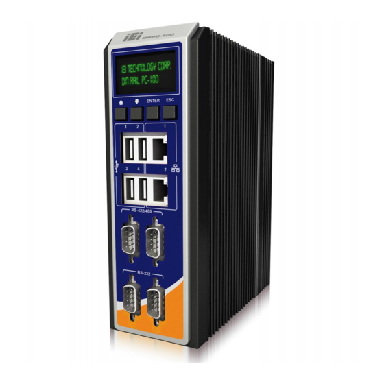
DRPC-100 Embedded System
IEI Technology Corp.
MODEL:
DRPC-100
Fanless Embedded System with Intel® Atom™ N2800 CPU,
DIN Rail Mounting Support, OLED Display or LED Indicators, Dual
9V~28V DC Power Input, RoHS Compliant
Rev. 1.01 – 22 January, 2016
GbE, USB, DIO, CAN-bus, Serial Ports,
User Manual
Page i
Advertisement
Table of Contents

Related Manuals for IEI Technology DRPC-100


Summary of Contents for IEI Technology DRPC-100
-
Page 1: User Manual
DRPC-100 Embedded System IEI Technology Corp. MODEL: DRPC-100 Fanless Embedded System with Intel® Atom™ N2800 CPU, DIN Rail Mounting Support, OLED Display or LED Indicators, Dual GbE, USB, DIO, CAN-bus, Serial Ports, 9V~28V DC Power Input, RoHS Compliant User Manual Page i Rev. - Page 2 DRPC-100 Embedded System Revision Date Version Changes 22 January, 2016 1.01 Updated the operating temperature range, packing list and DIN rail mounting method 16 November, 2012 1.00 Initial release Page ii...
- Page 3 DRPC-100 Embedded System Copyright COPYRIGHT NOTICE The information in this document is subject to change without prior notice in order to improve reliability, design and function and does not represent a commitment on the part of the manufacturer. In no event will the manufacturer be liable for direct, indirect, special, incidental, or consequential damages arising out of the use or inability to use the product or documentation, even if advised of the possibility of such damages.
-
Page 4: Table Of Contents
DRPC-100 Embedded System Table of Contents 1 INTRODUCTION ......................1 1.1 O ........................2 VERVIEW 1.2 M ....................2 ODEL ARIATIONS 1.3 F ........................3 EATURES 1.4 C ....................4 ONNECTOR ANEL 1.4.1 Front Panel ......................4 1.4.2 Top Panel ......................5 1.5 LED I... - Page 5 DRPC-100 Embedded System 3.8.3 LAN Connectors ....................27 3.8.4 Power Input, 3-pin Terminal Block ..............29 3.8.5 RS-232 Serial Port Connectors ................ 30 3.8.6 RS-422/485 Serial Port Connectors ..............31 3.8.7 USB Connectors ....................33 3.8.8 VGA Connector ....................34 3.9 D...
- Page 6 5.5 B ........................65 5.6 S ......................... 67 ECURITY 5.7 S & E ......................68 6 PROGRAMMABLE OLED DISPLAY (DRPC-100-CV-OLED ONLY) ....70 6.1 O ........................ 71 VERVIEW 6.2 OLED I ....................71 MAGE DITOR 6.2.1 OLED Image Editor Installation ..............71 6.2.2 Launching the OLED Image Editor ..............
- Page 7 DRPC-100 Embedded System 7.3.4 RJ-45 LAN Connectors (LAN/USB1, LAN/USB2) ........... 90 7.3.5 RS-232 Serial Ports (COM1/2) ................ 90 7.3.6 RS-422/485 Serial Ports (COM3/4) ..............90 7.3.7 USB 2.0 Connectors (LAN/USB1, LAN/USB2) ..........91 7.3.8 VGA Connector (VGA1) ................... 91 7.4 J ....................
- Page 8 DRPC-100 Embedded System A.7.1 Using AHCI Mode or ALi M5283 / VIA VT6421A Controller ....... 132 A.7.2 System Memory Requirement ................ 134 B SAFETY PRECAUTIONS ..................135 B.1 S ................... 136 AFETY RECAUTIONS B.1.1 General Safety Precautions ................136 B.1.2 Anti-static Precautions .................. 137 B.1.3 Explanation of Graphical Symbols ..............
- Page 9 DRPC-100 Embedded System List of Figures Figure 1-1: DRPC-100 ........................2 Figure 1-2: DRPC-100 Front Panel ....................4 Figure 1-3: DRPC-100 Top Panel ....................5 Figure 1-4: DRPC-100-CV-LED LED Indicators ................6 Figure 1-5: Physical Dimensions (millimeters) ................9 Figure 3-1: CF Card Slot Cover ....................16 Figure 3-2: CF Card Installation ....................17...
- Page 10 DRPC-100 Embedded System Figure 3-26: VGA Connector .......................35 Figure 3-27: VGA Connector .......................35 Figure 4-1: SO-DIMM Module Location..................39 Figure 4-2: SO-DIMM Module Installation...................40 Figure 6-1: OLED Image Editor Setup Wizard ................72 Figure 6-2: Select Installation Folder..................72 Figure 6-3: Confirm Installation ....................73 Figure 6-4: Installation Complete ....................73...
- Page 11 DRPC-100 Embedded System Figure A-18: Image Creation Confirmation ................109 Figure A-19: Image Creation Process..................109 Figure A-20: Image Creation Complete ..................110 Figure A-21: Press Any Key to Continue .................110 Figure A-22: Auto Recovery Utility ...................111 Figure A-23: Disable Automatically Restart ................112 Figure A-24: Launching the Recovery Tool ................113...
- Page 12 DRPC-100 Embedded System List of Tables Table 1-1: DRPC-100 Model Variations ..................2 Table 1-2: DRPC-100-CV-LED LED Definitions ................6 Table 1-3: Technical Specifications ....................8 Table 3-1: Jumpers ........................22 Table 3-2: Clear CMOS Jumper Settings ..................22 Table 3-3: CAN-bus Terminal Block Pinouts ................26 Table 3-4: DIO Terminal Block Pinouts ..................26...
- Page 13 DRPC-100 Embedded System Table 7-16: Power Input Terminal Block (DC_CN1) Pinouts ............89 Table 7-17: RJ-45 LAN Connector Pinouts ................90 Table 7-18: RS-232 Serial Port Pinouts ..................90 Table 7-19: RS-422/485 Serial Port Pinouts ................90 Table 7-20: USB 2.0 Connectors (LAN/USB1, LAN/USB2) Pinouts .........91 Table 7-21: VGA Connector (VGA1) Pinouts ................91...
-
Page 15: Introduction
DRPC-100 Embedded System 4Chapter Introduction Page 1... -
Page 16: Overview
Intel® NM10 chipset. It is designed for harsh environment applications and supports DIN rail mounting method. The DRPC-100 accepts a wide range of DC power input (9V~28V), allowing it to be powered anywhere. Four USB 2.0, two GbE, two RS-232, two RS-422/485, two CAN-bus and one 8-bit DIO provide rich I/O options for various applications. -
Page 17: Features
DRPC-100 Embedded System 1.3 Features The DRPC-100 features are listed below: Intel® Atom™ N2800 processor Low power consumption Fanless design DIN rail mounting support Intel® GMA 3650 with 640 MHz graphics core speed supports Blu-ray 2.0, DirectX 9, MPEG-2, H.264, C-1 and 1080p decoding... -
Page 18: Connector Panel
DRPC-100 Embedded System 1.4 Connector Panel 1.4.1 Front Panel The DRPC-100 front panel contains: 2 x RJ-45 Gigabit LAN ports 2 x RS-232 serial ports with isolation 2 x RS-422/485 serial ports with isolation 4 x USB 2.0 ports ... -
Page 19: Top Panel
DRPC-100 Embedded System 1.4.2 Top Panel The DRPC-100 top panel contains: 1 x AT/ATX power switch 1 x CompactFlash® card slot 1 x 9V~28V DC power terminal block 1 x Power button 1 x Reset button ... -
Page 20: Led Indicators (Drpc-100-Cv-Led Only)
DRPC-100 Embedded System 1.5 LED Indicators (DRPC-100-CV-LED Only) The LED indicators on the front panel of the DRPC-100-CV-LED are shown in Figure 1-4. Figure 1-4: DRPC-100-CV-LED LED Indicators All the LED definitions are listed in Table 1-2. Color Status Description... -
Page 21: Programmable Oled Display (Drpc-100-Cv-Oled Only)
DRPC-100 Embedded System 1.6 Programmable OLED Display (DRPC-100-CV-OLED Only) For programming the OLED display on the front panel of the DRPC-100-CV-OLED, refer to Chapter 6. 1.7 Technical Specifications The DRPC-100 technical specifications are listed in Table 1-3. Specifications System 1.86 GHz Intel® Atom™ N2800 dual-core processor Intel®... -
Page 22: Table 1-3: Technical Specifications
DRPC-100 Embedded System Specifications Power button Buttons Reset button Power 9V~28V DC (3-pin terminal block) Power Input 12V@1.85A (1.86 GHz Intel® Atom™ N2800 dual-core CPU with Power Consumption 2 GB 1066 MHz DDR3 SO-DIMM) AT/ATX switch AT/ATX Mode Environmental and Mechanical... -
Page 23: Dimensions
DRPC-100 Embedded System 1.8 Dimensions The physical dimensions are shown below: Figure 1-5: Physical Dimensions (millimeters) Page 9... -
Page 24: Unpacking
DRPC-100 Embedded System Chapter Unpacking Page 10... -
Page 25: Anti-Static Precautions
Follow the anti-static precautions outlined in Section 2.1. Make sure the packing box is facing upwards so the DRPC-100 does not fall out of the box. Make sure all the components shown in Section 2.3 are present. -
Page 26: Unpacking Checklist
If some of the components listed in the checklist below are missing, please do not proceed with the installation. Contact the IEI reseller or vendor you purchased the DRPC-100 from or contact an IEI sales representative directly. To contact an IEI sales representative, please send an email to sales@iei.com.tw. - Page 27 DRPC-100 Embedded System Quantity Item and Part Number Image Standard Screw (for securing an PCIe Mini card) (P/N: 44003-020031-RS) One Key Recovery CD User manual and driver CD The following table lists the optional items that can be purchased separately.
-
Page 28: Installation
DRPC-100 Embedded System Chapter Installation Page 14... -
Page 29: Installation Precautions
Air Circulation: Make sure there is sufficient air circulation when installing the DRPC-100. The DRPC-100’s cooling vents must not be obstructed by any objects. Blocking the vents can cause overheating of the DRPC-100. Leave at least 5 cm of clearance around the DRPC-100 to prevent overheating. -
Page 30: Cf Card Installation
To install the CF card, please follow the steps below: Step 1: Locate the CF card slot on the top panel of the DRPC-100. Step 2: Release the retention screw that secures the CF card slot cover, and then open the cover as shown in Figure 3-1. -
Page 31: Motherboard Removal
Figure 3-3: Replacing the CF Card Slot Cover 3.3 Motherboard Removal Before the jumper settings can be configured and the mSATA SSD can be installed, the motherboard must be removed from the DRPC-100. Follow the steps below to complete the task. Step 1: Remove the retention screws indicated in Figure 3-4. -
Page 32: Figure 3-4: Retention Screws
Remove the hex nuts on the front panel (Figure 3-5). Gently pull the front panel Step 2: out of the DRPC-100. Figure 3-5: Hex Nuts on the Front Panel Remove the hex nuts on the top panel (Figure 3-6). Gently pull the top panel out Step 3: of the DRPC-100. -
Page 33: Msata Ssd Installation
(Figure 3-7) on the solder side of the motherboard. Figure 3-7: Retention Screws on the Motherboard 3.4 mSATA SSD Installation The DRPC-100 has one PCIe Mini slot on the motherboard for mSATA SSD installation. To install the mSATA SSD, follow the instructions below. Step 1: Before accessing the motherboard, it has to be removed from the DRPC-100. -
Page 34: Figure 3-8: Pcie Mini Slot Location
DRPC-100 Embedded System Figure 3-8: PCIe Mini Slot Location Step 3: Insert into the socket at an angle. Line up the notch on the card with the notch on the connector. Slide the PCIe Mini card into the socket at an angle of about 20º... -
Page 35: Jumper Settings
OPEN a jumper means removing the plastic clip from a jumper. The jumpers on the DRPC-100 motherboard are listed in Table 3-1. The JP3 and JP4 543H jumpers are preconfigured for the DRPC-100. Users should not change these jumpers. Description Label Type Clear CMOS... -
Page 36: Access The Jumpers
Figure 3-11 550H If the DRPC-100 fails to boot due to improper BIOS settings, the clear CMOS jumper clears the CMOS data and resets the system BIOS information. To do this, use the jumper cap to close the pins for a few seconds then remove the jumper clip. -
Page 37: At/Atx Mode Selection
Figure 3-11: Clear CMOS Jumper Location 3.6 AT/ATX Mode Selection AT and ATX power modes can both be used on the DRPC-100. The selection is made through an AT/ATX switch on the top panel as shown below (Figure 3-12). Figure 3-12: AT/ATX Switch Location... -
Page 38: Mounting The System
DRPC-100 Embedded System 3.7 Mounting the System The DRPC-100 embedded system can be mounted onto a DIN rail. Follow the steps below to complete the task. Attach the supplied DIN rail mounting bracket to the rear panel of the embedded system. -
Page 39: External Peripheral Interface Connectors
Push the DIN rail inward until it clips in place (Figure 3-15). Step 3: Figure 3-15: Mounting the DIN Rail 3.8 External Peripheral Interface Connectors The DRPC-100 has the following connectors. Detailed descriptions of the connectors can be found in the subsections below. 8-bit DIO ... -
Page 40: Digital Input/Output Terminal Block
DRPC-100 Embedded System The Phoenix terminal block with 3KV isolation protection supports 2-port CAN-bus. The pinouts of the terminal block are shown in the table below. Description Description CAN1H CAN2H CAN1L CAN2L CAN1_GROUND CAN2_GROUND Table 3-3: CAN-bus Terminal Block Pinouts Figure 3-16: CAN-bus Terminal Block Pinout Location 3.8.2 Digital Input/Output Terminal Block... -
Page 41: Lan Connectors
Locate the RJ-45 connectors. The locations of the RJ-45 connectors are Step 1: shown in Figure 1-2. Step 2: Align the connectors. Align the RJ-45 connector on the LAN cable with one of the RJ-45 connectors on the DRPC-100. See Figure 3-18. Page 27... -
Page 42: Figure 3-18: Lan Connection
DRPC-100 Embedded System Figure 3-18: LAN Connection Step 3: Insert the LAN cable RJ-45 connector. Once aligned, gently insert the LAN cable RJ-45 connector into the on-board RJ-45 connector. Description Description MD0+ MD2+ MD0- MD2- MD1+ MD3+ MD1- MD3- Table 3-5: LAN Pinouts Figure 3-19: RJ-45 Ethernet Connector The RJ-45 Ethernet connector has two status LEDs, one green and one yellow. -
Page 43: Power Input, 3-Pin Terminal Block
DRPC-100 Embedded System Activity/Link LED Speed LED DESCRIPTION STATUS DESCRIPTION STATUS No link 10 Mbps connection Yellow Linked Green 100 Mbps connection Blinking TX/RX activity Orange 1 Gbps connection Table 3-6: RJ-45 Ethernet Connector LEDs 3.8.4 Power Input, 3-pin Terminal Block... -
Page 44: Serial Port Connectors
DRPC-100 Embedded System 3.8.5 RS-232 Serial Port Connectors COM1 and COM2 CN Label: DB-9 connectors CN Type: CN Location: See Figure 1-2 CN Pinouts: See Table 3-8 and Figure 3-22 RS-232 serial port devices can be attached to the DB-9 ports on the front panel. -
Page 45: Rs-422/485 Serial Port Connectors
DRPC-100 Embedded System Description Description Table 3-8: RS-232 Serial Port Pinouts Figure 3-22:RS-232 Serial Port Pinout Location 3.8.6 RS-422/485 Serial Port Connectors CN Label: COM3 and COM4 CN Type: DB-9 connectors See Figure 1-2 CN Location: See Table 3-9 and Figure 3-24 CN Pinouts: RS-422/485 serial port devices can be attached to the DB-9 ports on the front panel. -
Page 46: Figure 3-23: Rs-422/485 Serial Device Connector
DRPC-100 Embedded System Figure 3-23: RS-422/485 Serial Device Connector Secure the connector. Secure the serial device connector to the external Step 3: interface by tightening the two retention screws on either side of the connector. Description Description RS422TX-/RS485D- RS422TX+/RS485D+ RS422RX+... -
Page 47: Usb Connectors
DRPC-100 Embedded System 3.8.7 USB Connectors USB port CN Type: CN Location: See Figure 1-2 CN Pinouts: See Table 3-10 The USB ports are for connecting USB peripheral devices to the system. Step 1: Locate the USB connectors. The locations of the USB connectors are shown in Figure 1-2. -
Page 48: Vga Connector
DB-15 connector on the external peripheral interface. Step 3: Insert the VGA connector. Once the connectors are properly aligned with, insert the male connector from the VGA screen cable into the female connector on the DRPC-100. See Figure 3-26. Page 34... -
Page 49: Figure 3-26: Vga Connector
DRPC-100 Embedded System Figure 3-26: VGA Connector Step 4: Secure the connector. Secure the DB-15 VGA connector from the VGA monitor to the external interface by tightening the two retention screws on either side of the connector. Figure 3-27: VGA Connector... -
Page 50: Driver Installation
DRPC-100 Embedded System 3.9 Driver Installation NOTE: The content of the CD may vary throughout the life cycle of the product and is subject to change without prior notice. Visit the IEI website or contact technical support for the latest updates. -
Page 51: System Maintenance
DRPC-100 Embedded System Chapter System Maintenance Page 37... -
Page 52: System Maintenance Introduction
Before accessing any DRPC-100 internal components, make sure all power to the system has been disconnected. Failing to do so may cause severe damage to the DRPC-100 and injury to the user. WARNING! Please take antistatic precautions when working with the internal components. -
Page 53: So-Dimm Replacement
DRPC-100 Embedded System 4.3 SO-DIMM Replacement To install/replace the SO-DIMM modules, please follow the steps below. Step 1: Remove the motherboard from the DRPC-100. Refer to Section 3.3. Locate the SO-DIMM module on the motherboard. Step 2: Figure 4-1: SO-DIMM Module Location... -
Page 54: Figure 4-2: So-Dimm Module Installation
DRPC-100 Embedded System Figure 4-2: SO-DIMM Module Installation Step 7: Push the new SO-DIMM module until it engages and the white plastic end clips click into place. Make sure the end clips are fully secured after installation. Step 0: Page 40... -
Page 55: Bios
DRPC-100 Embedded System Chapter BIOS Page 41... -
Page 56: Introduction
DRPC-100 Embedded System 5.1 Introduction The BIOS is programmed onto the BIOS chip. The BIOS setup program allows changes to certain system settings. This chapter outlines the options that can be changed. 5.1.1 Starting Setup The UEFI BIOS is activated when the computer is turned on. The setup program can be activated in one of two ways. -
Page 57: Getting Help
DRPC-100 Embedded System Function Main Menu – Quit and not save changes into CMOS Esc key Status Page Setup Menu and Option Page Setup Menu -- Exit current page and return to Main Menu General help, only for Status Page Setup Menu and Option... -
Page 58: Main
DRPC-100 Embedded System 5.2 Main The Main BIOS menu (BIOS Menu 1) appears when the BIOS Setup program is entered. The Main menu gives an overview of the basic system information. Aptio Setup Utility – Copyright (C) 2011 American Megatrends, Inc. -
Page 59: Advanced
DRPC-100 Embedded System System Time [xx:xx:xx] Use the System Time option to set the system time. Manually enter the hours, minutes and seconds. 5.3 Advanced Use the Advanced menu (BIOS Menu 2) to configure the CPU and peripheral devices... -
Page 60: Acpi Settings
DRPC-100 Embedded System 5.3.1 ACPI Settings The ACPI Settings menu (BIOS Menu 3) configures the Advanced Configuration and Power Interface (ACPI) options. Aptio Setup Utility – Copyright (C) 2011 American Megatrends, Inc. Advanced ACPI Settings Select the highest ACPI sleep state the system... -
Page 61: Cpu Configuration
DRPC-100 Embedded System 5.3.2 CPU Configuration Use the CPU Configuration menu (BIOS Menu 4) to view detailed CPU specifications and configure the CPU. Aptio Setup Utility – Copyright (C) 2011 American Megatrends, Inc. Advanced CPU Configuration Enabled for Windows XP... -
Page 62: Ide Configuration
DRPC-100 Embedded System Hyper-Threading [Enabled] Use the Hyper-Threading function to enable or disable the Intel Hyper-Threading Technology. Disables the Intel Hyper-Threading Technology. Disabled Enabled Enables the Intel Hyper-Threading Technology. EFAULT 5.3.3 IDE Configuration Use the IDE Configuration menu (BIOS Menu 5) to change and/or set the configuration of the SATA devices installed in the system. -
Page 63: Usb Configuration
DRPC-100 Embedded System SATA Port 0/1 Hot Plug [Enabled] Use the SATA Port 0/1 Hot Plug option to enable or disable the hot-plug function of the SATA port 0 or 1. Enables the hot-plug function of the SATA port. -
Page 64: F81866 Super Io Configuration
DRPC-100 Embedded System keyboard can control the system even when there is no USB driver loaded onto the system. Enabled Legacy USB support enabled EFAULT Disabled Legacy USB support disabled Legacy USB support disabled if no USB devices are... -
Page 65: Serial Port N Configuration
DRPC-100 Embedded System 5.3.5.1 Serial Port n Configuration Use the Serial Port n Configuration menu (BIOS Menu 8) to configure the serial port n. Aptio Setup Utility – Copyright (C) 2011 American Megatrends, Inc. Advanced Serial Port n Configuration Enable or Disable Serial... - Page 66 DRPC-100 Embedded System Serial Port I/O port address is 3F8h and the interrupt IO=3F8h; IRQ=3, 4, address is IRQ3, 4, 5, 6, 7, 10, 11, 12 5, 6, 7, 10, 11, 12 Serial Port I/O port address is 2F8h and the interrupt IO=2F8h;...
- Page 67 DRPC-100 Embedded System Serial Port I/O port address is 2F8h and the interrupt IO=2F8h; IRQ=3 address is IRQ3 IO=3F8h; Serial Port I/O port address is 3F8h and the interrupt address is IRQ3, 4, 5, 6, 7, 10, 11, 12...
- Page 68 DRPC-100 Embedded System The serial port IO port address and interrupt address Auto EFAULT are automatically detected. IO=3E8h; Serial Port I/O port address is 3E8h and the interrupt address is IRQ7 IRQ=7 IO=3F8h; Serial Port I/O port address is 3F8h and the interrupt...
- Page 69 DRPC-100 Embedded System 5.3.5.1.4 Serial Port 4 Configuration Serial Port [Enabled] Use the Serial Port option to enable or disable the serial port. Disabled Disable the serial port Enabled Enable the serial port EFAULT Change Settings [Auto] Use the Change Settings option to change the serial port IO port address and interrupt address.
- Page 70 DRPC-100 Embedded System Serial Port I/O port address is 2F0h and the interrupt IO=2F0h; IRQ=3, 4, address is IRQ3, 4, 5, 6, 7, 10, 11, 12 5, 6, 7, 10, 11, 12 Serial Port I/O port address is 2E0h and the interrupt IO=2E0h;...
-
Page 71: F81866 H/W Monitor
DRPC-100 Embedded System Serial Port I/O port address is 2F8h and the interrupt O=2F8h; IRQ=3, 4, address is IRQ3, 4, 5, 6, 7, 10, 11, 12 5, 6, 7, 10, 11, 12 Serial Port I/O port address is 3E8h and the interrupt IO=3E8h;... - Page 72 DRPC-100 Embedded System Aptio Setup Utility – Copyright (C) 2011 American Megatrends, Inc. Advanced PC Health Status Smart Fan Mode Select > Smart Fan Mode Configuration CPU Temperature : +51 C System Temperature : +49 C CPU_FAN1 Speed : N/A +VCC_CPU : +1.200 V...
-
Page 73: Smart Fan Mode Configuration
DRPC-100 Embedded System 5.3.6.1 Smart Fan Mode Configuration Use the Smart Fan Mode Configuration submenu (BIOS Menu 10) to configure fan temperature and speed settings. Aptio Setup Utility – Copyright (C) 2011 American Megatrends, Inc. Advanced Smart Fan Mode Configuration... -
Page 74: Serial Port Console Redirection
DRPC-100 Embedded System 5.3.7 Serial Port Console Redirection The Serial Port Console Redirection menu (BIOS Menu 11) allows the console redirection options to be configured. Console redirection allows users to maintain a system remotely by re-directing keyboard input and text output through the serial port. - Page 75 DRPC-100 Embedded System Bits per second [115200] Use the Bits per second option to specify the serial port transmission speed. The speed must match the other side. Long or noisy lines may require lower speeds. Sets the serial port transmission speed at 9600.
-
Page 76: Chipset
DRPC-100 Embedded System Stop Bits [1] Use the Stop Bits option to specify the number of stop bits used to indicate the end of a serial data packet. Communication with slow devices may require more than 1 stop bit. -
Page 77: Host Bridge Configuration
DRPC-100 Embedded System 5.4.1 Host Bridge Configuration Use the Host Bridge Configuration menu (BIOS Menu 13) to configure the Intel IGD Configuration and display the memory information. Aptio Setup Utility – Copyright (C) 2011 American Megatrends, Inc. Chipset > Intel IGD Configuration Config Intel IGD Settings. -
Page 78: South Bridge Configuration
DRPC-100 Embedded System Fixed Graphics Memory Size [128MB] Use the Fixed Graphics Memory Size option to specify the maximum amount of memory that can be allocated as graphics memory. Configuration options are listed below. 128MB EFAULT 256MB 5.4.2 South Bridge Configuration... -
Page 79: Boot
DRPC-100 Embedded System Power Saving Function(ERP) [Disabled] Use the Power Saving Function(ERP) option to enable or disable the power saving function. Disables the power saving function. Disabled EFAULT Enabled Enables the power saving function. Restore AC Power Loss [Last State] Use the Restore AC Power Loss BIOS option to specify what state the system returns to if there is a sudden loss of power to the system. - Page 80 DRPC-100 Embedded System Bootup NumLock State [On] Use the Bootup NumLock State BIOS option to specify if the number lock setting must be modified during boot up. Allows the Number Lock on the keyboard to be EFAULT enabled automatically when the computer system boots up.
-
Page 81: Security
DRPC-100 Embedded System Option ROM Messages [Force BIOS] Use the Option ROM Messages option to set the Option ROM display mode. Force Sets display mode to force BIOS. EFAULT BIOS Keep Sets display mode to current. Current 5.6 Security... -
Page 82: Save & Exit
DRPC-100 Embedded System 5.7 Save & Exit Use the Save & Exit menu (BIOS Menu 18) to load default BIOS values, optimal failsafe values and to save configuration changes. Aptio Setup Utility – Copyright (C) 2011 American Megatrends, Inc. Main... - Page 83 DRPC-100 Embedded System Save as User Defaults Use the Save as User Defaults option to save the changes done so far as user defaults. Restore User Defaults Use the Restore User Defaults option to restore the user defaults to all the setup options.
-
Page 84: Programmable Oled Display (Drpc-100-Cv-Oled Only)
DRPC-100 Embedded System Chapter Programmable OLED Display (DRPC-100-CV-OLED Only) Page 70... -
Page 85: Overview
DRPC-100 Embedded System 6.1 Overview The DRPC-100-CV-OLED comes with a programmable OLED display that allows users to program their own APIs to show any information on it in graphic and text formats. The driver CD includes two programs as below: ... -
Page 86: Figure 6-1: Oled Image Editor Setup Wizard
DRPC-100 Embedded System Figure 6-1: OLED Image Editor Setup Wizard Step 4: Select a folder for OLED Image Editor Installation in Figure 6-2. Click Next to continue. Figure 6-2: Select Installation Folder Page 72... -
Page 87: Figure 6-3: Confirm Installation
DRPC-100 Embedded System The following screen appears. Click Next to confirm the installation. Step 5: Figure 6-3: Confirm Installation The system starts installing the OLED Image Editor. Step 6: When the OLED Image Editor is successfully installed, the following window Step 7: appears. -
Page 88: Launching The Oled Image Editor
DRPC-100 Embedded System 6.2.2 Launching the OLED Image Editor To launch the OLED Image Editor, double click the OLED Image Editor icon on the desktop. Figure 6-5: OLED Image Editor 6.2.3 Function List The OLED Image Editor provides picture drawing function. Users can draw simple pictures on the Canvas field. -
Page 89: Oled Control
DRPC-100 Embedded System OPEN: Allows loading a 24-bit BMP file. The resolution of the 24-bit BMP file must be 128 x 64. SAVE: Allows saving as a BMP file. The file must be saved as 24-bit BMP with 128 x 64 resolution. -
Page 90: Oled Erase Page
DRPC-100 Embedded System to the indicated page number. When writing an image into the OLED module, the OLED Status field displays “The page is under writing. Please wait…”. Wait for several seconds. When finished, “Write Page Done” is displayed. ... -
Page 91: Drpc100 Demo Program
DRPC-100 Embedded System 6.3 DRPC100 Demo Program NOTE: Refer to the DRPC100-Matrix LED UART Protocol reference manual packaged in the driver CD for detailed setup. The DRPC100 Demo Program allows displaying information in text format. To launch the DRPC100, double click the DRPC100_OLED_DEMO file located in the DEMO APP folder of the driver CD. -
Page 92: Dialog Menu
DRPC-100 Embedded System 6.3.1 Dialog Menu The Dialog menu allows clearing the OLED screen and getting ID. Figure 6-10: Dialog Menu Get ID: Clicks to get ID. Clr OLED: Clicks to clear the OLED screen. Close: Clicks to return to the main menu. -
Page 93: Lcd Menu
DRPC-100 Embedded System 6.3.2 LCD Menu The LCD menu allows entering text to be displayed on the OLED display. Figure 6-11: LCD Menu Send: Clicks to send the input text to be displayed on the OLED display. Clear: Clears the input text. -
Page 94: Demo Menu
DRPC-100 Embedded System 6.3.3 DEMO Menu The DEMO menu lists the activities of the function keys. Click Close to return to the main menu. Figure 6-12: DEMO Menu Page 80... -
Page 95: Interface Connectors
DRPC-100 Embedded System Chapter Interface Connectors Page 81... -
Page 96: Peripheral Interface Connectors
DRPC-100 Embedded System 7.1 Peripheral Interface Connectors The DRPC-100 embedded system motherboard comes with a number of peripheral interface connectors and configuration jumpers. The connector locations are shown in Figure 6-1 and Figure 6-2. The Pin 1 locations of the on-board connectors are also indicated in the diagrams. -
Page 97: Internal Peripheral Connectors
Internal peripheral connectors are found on the motherboard and are only accessible when the motherboard is outside of the chassis. The table below shows a list of the peripheral interface connectors on the DRPC-100 motherboard. Pinouts of these connectors can be found in the following sections. -
Page 98: Burn In Can-Bus Firmware Connector (Cn4)
DRPC-100 Embedded System 7.2.2 Burn in CAN-bus Firmware Connector (CN4) PIN NO. DESCRIPTION PIN NO. DESCRIPTION Table 7-3: Burn in CAN-bus Firmware Connector (CN4) Pinouts 7.2.3 Burn in MCU Firmware Connector (JP5) PIN NO. DESCRIPTION MCLR +V5S ICSPDAT ICSPCLK Table 7-4: Burn in MCU Firmware (JP5) Pinouts 7.2.4 CompactFlash®... -
Page 99: Cpu Fan Connector (Cpu_Fan1)
DRPC-100 Embedded System PIN NO. DESCRIPTION PIN NO. DESCRIPTION VCC_COM VCC_COM GROUND GROUND GROUND S_RST GROUND S_IORDY S_DA2 S_DRQ S_DA1 S_DACK# S_DA0 SIDE_LED# S_D0 S_PCBLID S_D1 S_D8 S_D2 S_D9 S_D10 CFD2 GROUND Table 7-5: CompactFlash® Card Slot (CF1) Pinouts 7.2.5 CPU Fan Connector (CPU_FAN1) PIN NO. -
Page 100: Indicator Connector (F_Panel1)
DRPC-100 Embedded System 7.2.6 Indicator Connector (F_PANEL1) PIN NO. DESCRIPTION PWR_LED+ PWR_LED- HDD_LED+ HDD_LED- Table 7-7: Indicator Connector (F_PANEL1) Pinouts 7.2.7 OLED/LED Signal Connector (OLED1) PIN NO. DESCRIPTION PIN NO. DESCRIPTION +12V LED_SDA GPIO LED_SCL GPIO RESET# Table 7-8: OLED/LED Signal Connector (OLED1) Pinouts 7.2.8 PCIe Mini Card Slot (M_PCIE1) -
Page 101: Sata 3Gb/S Connectors(Sata1)
DRPC-100 Embedded System PIN NO. DESCRIPTION PIN NO. DESCRIPTION PCIRST# PERN2 3VDual PERP2 1.5V SMBCLK PETN2 SMBDATA PETP2 USBD- USBD+ 1.5V VCC3 Table 7-9: PCIe Mini Card Slot (M_PCIE1) Pinouts 7.2.9 SATA 3Gb/s Connectors(SATA1) PIN NO. DESCRIPTION Table 7-10: SATA 3Gb/s Connector (SATA1) Pinouts... -
Page 102: Sata Power Connector (Sata_Pwr1)
SPI_CLK SPI_MOSI Table 7-12: SPI Flash Connector (SPI1) Pinouts 7.3 External Interface Panel Connectors The table below lists the rear panel connectors on the DRPC-100 motherboard. Pinouts of these connectors can be found in the following sections. Connector Type Label... -
Page 103: Can-Bus Terminal Block (Can1)
DRPC-100 Embedded System Connector Type Label RS-232 serial ports DB-9 COM1/2 RS-422/485 serial ports DB-9 COM3/4 VGA connector 15-pin female Table 7-13: Rear Panel Connectors 7.3.1 CAN-bus Terminal Block (CAN1) PIN NO. DESCRIPTION PIN NO. DESCRIPTION CAN1H CAN2H CAN1L CAN2L... -
Page 104: Lan Connectors (Lan/Usb1, Lan/Usb2)
DRPC-100 Embedded System 7.3.4 RJ-45 LAN Connectors (LAN/USB1, LAN/USB2) PIN NO. DESCRIPTION PIN NO. DESCRIPTION MD0+ MD2+ MD0- MD2- MD1+ MD3+ MD1- MD3- Table 7-17: RJ-45 LAN Connector Pinouts 7.3.5 RS-232 Serial Ports (COM1/2) PIN NO. DESCRIPTION PIN NO. DESCRIPTION Table 7-18: RS-232 Serial Port Pinouts 7.3.6 RS-422/485 Serial Ports (COM3/4) -
Page 105: Usb 2.0 Connectors (Lan/Usb1, Lan/Usb2)
DDC DAT HSYNC VSYNC DDCCLK Table 7-21: VGA Connector (VGA1) Pinouts 7.4 Jumper Settings The JP3 and JP4 jumpers are preconfigured for the DRPC-100. Users should not change these jumpers. It is only for reference. Jumper Name Label Type Clear CMOS... -
Page 106: Clear Cmos Jumper (Jp1)
DRPC-100 Embedded System 7.4.1 Clear CMOS Jumper (JP1) Description Short 1-2 Keep CMOS Setup (Default) Short 2-3 Clear CMOS Setup Table 7-23: Clear CMOS Jumper (JP1) Settings 7.4.2 CAN-bus 1 Long Wire Transmitting Jumper (JP3) Description CAN1H CAN1L Table 7-24: C CAN-bus 1 Long Wire Transmitting Jumper (JP3) Settings 7.4.3 CAN-bus 2 Long Wire Transmitting Jumper (JP4) -
Page 107: A One Key Recovery
DRPC-100 Embedded System Appendix One Key Recovery Page 93... -
Page 108: One Key Recovery Introduction
DRPC-100 Embedded System A.1 One Key Recovery Introduction The IEI one key recovery is an easy-to-use front end for the Norton Ghost system backup and recovery tool. This tool provides quick and easy shortcuts for creating a backup and reverting to that backup or reverting to the factory default settings. -
Page 109: System Requirement
DRPC-100 Embedded System After completing the five initial setup procedures as described above, users can access the recovery tool by pressing <F3> while booting up the system. The detailed information of each function is described in Section A.5. NOTE: The initial setup procedures for Linux system are described in Section A.3. -
Page 110: Supported Operating System
DRPC-100 Embedded System partitions. Please take the following table as a reference when calculating the size of the partition. OS Image after Ghost Compression Ratio Windows® 7 7 GB 5 GB Windows® XPE 776 MB 560 MB Windows® CE 6.0... -
Page 111: Setup Procedure For Windows
DRPC-100 Embedded System Linux Fedora Core 12 (Constantine) Fedora Core 11 (Leonidas) Fedora Core 10 (Cambridge) Fedora Core 8 (Werewolf) Fedora Core 7 (Moonshine) RedHat RHEL-5.4 RedHat 9 (Ghirke) Ubuntu 8.10 (Intrepid) Ubuntu 7.10 (Gutsy) Ubuntu 6.10 (Edgy) Debian 5.0 (Lenny) Debian 4.0 (Etch) -
Page 112: Hardware And Bios Setup
DRPC-100 Embedded System NOTE: The setup procedures described below are for Microsoft Windows operating system users. For Linux, most of the setup procedures are the same except for several steps described in Section A.3. A.2.1 Hardware and BIOS Setup Step 1: Make sure the system is powered off and unplugged. -
Page 113: Figure A-2: Launching The Recovery Tool
DRPC-100 Embedded System Figure A-2: Launching the Recovery Tool The recovery tool setup menu is shown as below. Step 3: Figure A-3: Recovery Tool Setup Menu Step 4: Press <6> then <Enter>. Page 99... -
Page 114: Figure A-4: Command Mode
DRPC-100 Embedded System Figure A-4: Command Mode The command prompt window appears. Type the following commands (marked Step 5: in red) to create two partitions. One is for the OS installation; the other is for saving recovery files and images which will be an invisible partition. -
Page 115: Figure A-5: Partition Creation Commands
DRPC-100 Embedded System Figure A-5: Partition Creation Commands Page 101... -
Page 116: Install Operating System, Drivers And Applications
DRPC-100 Embedded System NOTE: Use the following commands to check if the partitions were created successfully. Press any key to exit the recovery tool and automatically reboot the system. Step 6: Please continue to the following procedure: Build-up Recovery Partition. -
Page 117: Build-Up Recovery Partition
DRPC-100 Embedded System A.2.4 Build-up Recovery Partition Put the recover CD in the optical drive. Step 1: Step 2: Start the system. Step 3: Boot the system from recovery CD. When prompted, press any key to boot from the recovery CD. It will take a while to launch the recovery tool. Please be... -
Page 118: Figure A-7: Manual Recovery Environment For Windows
DRPC-100 Embedded System Figure A-7: Manual Recovery Environment for Windows The Symantec Ghost window appears and starts configuring the system to build Step 5: a recovery partition. In this process the partition created for recovery files in Section A.2.2 is hidden and the recovery tool is saved in this partition. -
Page 119: Create Factory Default Image
DRPC-100 Embedded System Figure A-9: Press Any Key to Continue Step 7: Eject the recovery CD. S t e p 0 : A.2.5 Create Factory Default Image NOTE: Before creating the factory default image, please configure the system to a factory default environment, including driver and application installations. -
Page 120: Figure A-11: Recovery Tool Menu
DRPC-100 Embedded System Figure A-11: Recovery Tool Menu Step 3: The About Symantec Ghost window appears. Click OK button to continue. Figure A-12: About Symantec Ghost Window Step 4: Use mouse to navigate to the option shown below ( Figure A-13). -
Page 121: Figure A-13: Symantec Ghost Path
DRPC-100 Embedded System Figure A-13: Symantec Ghost Path Step 5: Select the local source drive (Drive 1) as shown in Figure A-14. Then click OK. 779H77 9H Figure A-14: Select a Local Source Drive Step 6: Select a source partition (Part 1) from basic drive as shown in Figure A-15. -
Page 122: Figure A-16: File Name To Copy Image To
DRPC-100 Embedded System Select 1.2: [Recovery] NTFS drive and enter a file name called Step 7: Figure A-16). Click Save. The factory default image will then be saved in the 781H781H selected recovery drive and named IEI.GHO. WARNING: The file name of the factory default image must be iei.GHO. -
Page 123: Figure A-17: Compress Image
DRPC-100 Embedded System When the Compress Image screen in Figure A-17 prompts, click High to make Step 8: 782H78 2H the image file smaller. Figure A-17: Compress Image The Proceed with partition image creation window appears, click Yes to Step 9: continue. -
Page 124: Auto Recovery Setup Procedure
DRPC-100 Embedded System When the image creation completes, a screen prompts as shown in Step 11: Figure A-20. Click Continue and close the Ghost window to exit the program. 784H784H Figure A-20: Image Creation Complete The recovery tool main menu window is shown as below. Press any key to Step 12: reboot the system. -
Page 125: Figure A-22: Auto Recovery Utility
DRPC-100 Embedded System CAUTION: The auto recovery function can only run on a Microsoft Windows system with the following OS versions: Windows 2000 Windows 7 Windows XP Windows XP Embedded Windows Vista Windows Embedded Standard 7... -
Page 126: Figure A-23: Disable Automatically Restart
DRPC-100 Embedded System Settings button of Startup and Recovery. Deselect “Automatically restart”. Click OK to save the settings and exit. (See Figure A-23) Figure A-23: Disable Automatically Restart Step 4: Reboot the system from the recovery CD. When prompted, press any key to boot from the recovery CD. -
Page 127: Figure A-24: Launching The Recovery Tool
DRPC-100 Embedded System Figure A-24: Launching the Recovery Tool When the recovery tool setup menu appears, press <4> then <Enter>. Step 5: Figure A-25: Auto Recovery Environment for Windows Step 6: The Symantec Ghost window appears and starts configuring the system to build an auto recovery partition. -
Page 128: Figure A-27: Factory Default Image Confirmation
DRPC-100 Embedded System process (The default option is YES). It is suggested to choose YES for this option. Figure A-27: Factory Default Image Confirmation The Symantec Ghost starts to create the factory default image (Figure A-28). Step 8: Figure A-28: Image Creation Complete... -
Page 129: Setup Procedure For Linux
DRPC-100 Embedded System Enable the Auto Recovery Function option (Advanced iEi Feature Auto Step 12: Recovery Function). BIOS SETUP UTILITY Main Advanced PCIPNP Boot Security Chipset Exit iEi Feature Auto Recovery Function [Enabled] Recover from PXE [Disabled] ... -
Page 130: Figure A-31: Partitions For Linux
DRPC-100 Embedded System NOTE: If the Linux OS is not installed with GRUB (v0.97 or earlier) and Ext3, the Symantec Ghost may not function properly. While installing Linux OS, please create two partitions: Partition 1: / Partition 2: SWAP... -
Page 131: Figure A-32: System Configuration For Linux
DRPC-100 Embedded System system32>format N: /fs:ntfs /q /v:Recovery /y system32>exit Step 4: Build-up recovery partition. Press any key to boot from the recovery CD. It will take a while to launch the recovery tool. Please be patient. When the recovery tool setup menu appears, type <3>... -
Page 132: Recovery Tool Functions
DRPC-100 Embedded System Modify the menu.lst as shown below. Step 6: Step 7: The recovery tool menu appears. ( Figure A-34) 788H78 8H Figure A-34: Recovery Tool Menu Create a factory default image. Follow Step 2 Step 12 described in Section Step 8: A.2.5 to create a factory default image. -
Page 133: Figure A-35: Recovery Tool Main Menu
DRPC-100 Embedded System Figure A-35: Recovery Tool Main Menu The recovery tool has several functions including: 1. Factory Restore: Restore the factory default image (iei.GHO) created in Section A.2.5. 79 0H79 0H 2. Backup system: Create a system backup image (iei_user.GHO) which will be saved in the hidden partition. -
Page 134: Factory Restore
DRPC-100 Embedded System A.5.1 Factory Restore To restore the factory default image, please follow the steps below. Step 1: Type <1> and press <Enter> in the main menu. The Symantec Ghost window appears and starts to restore the factory default. A Step 2: factory default image called iei.GHO is created in the hidden Recovery partition. -
Page 135: Backup System
DRPC-100 Embedded System A.5.2 Backup System To backup the system, please follow the steps below. Step 1: Type <2> and press <Enter> in the main menu. The Symantec Ghost window appears and starts to backup the system. A Step 2: backup image called iei_user.GHO is created in the hidden Recovery partition. -
Page 136: Restore Your Last Backup
DRPC-100 Embedded System A.5.3 Restore Your Last Backup To restore the last system backup, please follow the steps below. Step 1: Type <3> and press <Enter> in the main menu. The Symantec Ghost window appears and starts to restore the last backup Step 2: image (iei_user.GHO). -
Page 137: Manual
DRPC-100 Embedded System A.5.4 Manual To restore the last system backup, please follow the steps below. Step 1: Type <4> and press <Enter> in the main menu. The Symantec Ghost window appears. Use the Ghost program to backup or Step 2: recover the system manually. -
Page 138: Configure Dhcp Server Settings
DRPC-100 Embedded System NOTE: The supported client OS includes: Windows 2000 Windows 7 Windows XP Windows CE Windows Vista Windows XP Embedded Prior to restoring client systems from a Linux server, a few setup procedures are required. - Page 139 DRPC-100 Embedded System Use the following command to copy the DHCP server sample to etc/dhcpd.conf: #cp /usr/share/doc/dhcp-3.0.5/dhcpd.conf.sample /etc/dhcpd.conf #vi /etc/dhcpd.conf Debian #vi /etc/dhcpd.conf Edit “/etc/dhcpd.conf” for your environment. For example, add next-server PXE server IP address; filename “pxelinux.0”; Page 125...
-
Page 140: Configure Tftp Settings
DRPC-100 Embedded System A.6.2 Configure TFTP Settings Install the tftp, httpd and syslinux. Step 1: #yum install tftp-server httpd syslinux (CentOS) #apt-get install tftpd-hpa xinetd syslinux (Debian) Enable the TFTP server by editing the “/etc/xinetd.d/tftp” file and make it use the Step 2: remap file. -
Page 141: Configure One Key Recovery Server Settings
DRPC-100 Embedded System #vi /etc/xinetd.d/tftp A.6.3 Configure One Key Recovery Server Settings Step 1: Copy the Utility/RECOVERYR10.TAR.BZ2 package from the One Key Recovery CD to the system (server side). Extract the recovery package to /. Step 2: #cp RecoveryR10.tar.bz2 / #cd / #tar –xvjf RecoveryR10.tar.bz2... -
Page 142: Create Shared Directory
DRPC-100 Embedded System Debian #/etc/init.d/xinetd reload #/etc/init.d/xinetd restart #/etc/init.d/dhcp3-server restart A.6.5 Create Shared Directory Install the samba. Step 1: #yum install samba Step 2: Create a shared directory for the factory default image. #mkdir /share #cd /share #mkdir /image #cp iei.gho /image WARNING: The file name of the factory default image must be iei.gho. -
Page 143: Setup A Client System For Auto Recovery
DRPC-100 Embedded System create mask = 0644 directory mask = 0755 Edit “/etc/samba/smb.conf” for your environment. For example: Step 4: Step 5: Modify the hostname #vi /etc/hostname Modify: RecoveryServer A.6.6 Setup a Client System for Auto Recovery Disable the automatically restart function before creating the factory Step 1: default image. -
Page 144: Figure A-43: Disable Automatically Restart
DRPC-100 Embedded System Figure A-43: Disable Automatically Restart Configure the following BIOS options of the client system. Step 2: Advanced → iEi Feature → Auto Recovery Function → Enabled Advanced → iEi Feature → Recover from PXE → Enabled Boot → Launch PXE OpROM → Enabled... - Page 145 DRPC-100 Embedded System Step 6: Restart the client system from LAN. If the system encounters a Blue Screen of Death (BSoD) or a hang for around 10 minutes, it will automatically restore from the factory default image. The following screens will show when the system starts auto recovering.
-
Page 146: Other Information
DRPC-100 Embedded System NOTE: A firewall or a SELinux is not in use in the whole setup process described above. If there is a firewall or a SELinux protecting the system, modify the configuration information to accommodate them. A.7 Other Information A.7.1 Using AHCI Mode or ALi M5283 / VIA VT6421A Controller... - Page 147 DRPC-100 Embedded System When the following window appears, press <S> to select “Specify Additional Step 5: Device”. Page 133...
-
Page 148: System Memory Requirement
DRPC-100 Embedded System In the following window, select a SATA controller mode used in the system. Then Step 6: press <Enter>. The user can now start using the SATA HDD. After pressing <Enter>, the system will get into the recovery tool setup menu. -
Page 149: B Safety Precautions
DRPC-100 Embedded System Appendix Safety Precautions Page 135... -
Page 150: Safety Precautions
DRPC-100 Embedded System B.1 Safety Precautions WARNING: The precautions outlined in this appendix should be strictly followed. Failure to follow these precautions may result in permanent damage to the DRPC-100. Please follow the safety precautions outlined in the sections that follow: B.1.1 General Safety Precautions... -
Page 151: Anti-Static Precautions
Electrostatic discharge (ESD) can cause serious damage to electronic components, including the DRPC-100. Dry climates are especially susceptible to ESD. It is therefore critical that whenever the DRPC-100 is opened and any of the electrical components are handled, the following anti-static precautions are strictly adhered to. -
Page 152: Product Disposal
When maintaining or cleaning the DRPC-100, please follow the guidelines below. B.2.1 Maintenance and Cleaning Prior to cleaning any part or component of the DRPC-100, please read the details below. The interior of the DRPC-100 does not require cleaning. Keep fluids away from the DRPC-100 interior. -
Page 153: Cleaning Tools
Some components in the DRPC-100 may only be cleaned using a product specifically designed for the purpose. In such case, the product will be explicitly mentioned in the cleaning tips. Below is a list of items to use when cleaning the DRPC-100. ... -
Page 154: C Digital I/O Interface
DRPC-100 Embedded System Appendix Digital I/O Interface Page 140... -
Page 155: Introduction
DRPC-100 Embedded System C.1 Introduction The DIO connector on the DRPC-100 is interfaced to GPIO ports on the Super I/O chipset. The DIO has both 4-bit digital inputs and 4-bit digital outputs. The digital inputs and digital outputs are generally control signals that control the on/off circuit of external devices or TTL devices. -
Page 156: Assembly Language Samples
DRPC-100 Embedded System C.3 Assembly Language Samples C.3.1 Enable the DIO Input Function The BIOS interrupt call INT 15H controls the digital I/O. An assembly program to enable digital I/O input functions is listed below. Sets the digital port as input... -
Page 157: D Hazardous Materials Disclosure
DRPC-100 Embedded System Appendix Hazardous Materials Disclosure Page 143... -
Page 158: Hazardous Materials Disclosure Table For Ipb Products Certified As Rohs Compliant Under 2002/95/Ec Without Mercury
DRPC-100 Embedded System D.1 Hazardous Materials Disclosure Table for IPB Products Certified as RoHS Compliant Under 2002/95/EC Without Mercury The details provided in this appendix are to ensure that the product is compliant with the Peoples Republic of China (China) RoHS standards. The table below acknowledges the presences of small quantities of certain materials in the product, and is applicable to China RoHS only. - Page 159 DRPC-100 Embedded System Part Name Toxic or Hazardous Substances and Elements Lead Mercury Cadmium Hexavalent Polybrominated Polybrominated (Pb) (Hg) (Cd) Chromium Biphenyls Diphenyl Ethers (CR(VI)) (PBB) (PBDE) Housing Display Printed Circuit Board Metal Fasteners Cable Assembly Fan Assembly Power Supply...
- Page 160 DRPC-100 Embedded System 此附件旨在确保本产品符合中国 RoHS 标准。以下表格标示此产品中某有毒物质的含量符 合中国 RoHS 标准规定的限量要求。 本产品上会附有”环境友好使用期限”的标签,此期限是估算这些物质”不会有泄漏或突变”的 年限。本产品可能包含有较短的环境友好使用期限的可替换元件,像是电池或灯管,这些元 件将会单独标示出来。 部件名称 有毒有害物质或元素 铅 汞 镉 六价铬 多溴联苯 多溴二苯 醚 (Pb) (Hg) (Cd) (CR(VI)) (PBB) (PBDE) 壳体 显示 印刷电路板 金属螺帽 电缆组装 风扇组装 电力供应组装 电池 O: 表示该有毒有害物质在该部件所有物质材料中的含量均在 SJ/T11363-2006 标准规定的限量要求以下。 X: 表示该有毒有害物质至少在该部件的某一均质材料中的含量超出 SJ/T11363-2006 标准规定的限量要求。...
Need help?
Do you have a question about the DRPC-100 and is the answer not in the manual?
Questions and answers