Table of Contents
Advertisement
Quick Links
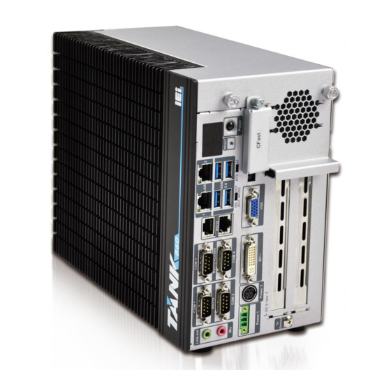
TANK-860-HM86 Em be d d e d S ys te m
MODEL:
TANK-860-HM86 S e rie s
Em b e d d e d S ys te m with 4th Ge n e ra tio n In te l® Co re ™ p ro c e s s o r,
VGA, DVI-I, Dis p la yP o rt, Two Gig a b it Eth e rn e t,
Fo u r US B 3.0, Two US B 2.0, RS -232/422/485,
Ro HS Co m p lia n t
Us e r Ma n u a l
P a g e i
Re v. 1.04 – 29 Ap ril 2015
Advertisement
Table of Contents

Related Manuals for IEI Technology TANK-860-HM86 Series


Summary of Contents for IEI Technology TANK-860-HM86 Series
- Page 1 TANK-860-HM86 Em be d d e d S ys te m MODEL: TANK-860-HM86 S e rie s Em b e d d e d S ys te m with 4th Ge n e ra tio n In te l® Co re ™ p ro c e s s o r, VGA, DVI-I, Dis p la yP o rt, Two Gig a b it Eth e rn e t, Fo u r US B 3.0, Two US B 2.0, RS -232/422/485, Ro HS Co m p lia n t...
- Page 2 TANK-860-HM86 Em b e d d e d S ys te m Re vis io n Date Version Changes 29 April 2015 1.04 Update Section 1.4: Technical Specifications ( Change Operating Temperature to -20°C ~ 60°C) 26 March 2015 1.03 Update P.N of system fan Add connector pinouts of backplane 12 March 2015...
- Page 3 TANK-860-HM86 Em be d d e d S ys te m Co p yrig h t COP YRIGHT NOTICE The information in this document is subject to change without prior notice in order to improve reliability, design and function and does not represent a commitment on the part of the manufacturer.
-
Page 4: Table Of Contents
TANK-860-HM86 Em b e d d e d S ys te m Ta b le o f Co n te n ts 1 INTRODUCTION ......................1 1.1 O ........................2 VERVIEW 1.2 M ..................... 3 ODEL ARIATIONS 1.3 F ........................3 EATURES 1.4 T .................. - Page 5 TANK-860-HM86 Em be d d e d S ys te m 3.6.3 Audio Connector ....................39 3.6.4 CFast Socket ....................40 3.6.5 Digital Input/Output Connector ............... 40 3.6.6 DVI Connector ....................40 3.6.7 LAN Connectors ....................41 3.6.8 Power Input, 3-pin Terminal Block ..............43 3.6.9 Power Input, 4-pin DIN Connector ..............
- Page 6 TANK-860-HM86 Em b e d d e d S ys te m 4.3.4 DVI Connector (DVI_1) ................... 58 4.3.5 Ethernet and USB3.0 Connectors (LAN1_USB1) ..........59 4.3.6 Ethernet and USB3.0 Connectors (LAN2_USB2) ..........59 4.3.7 Power Connector (PWR1) ................60 4.3.8 Power Connector (PWR2) ................
- Page 7 TANK-860-HM86 Em be d d e d S ys te m 5.4.1 PCH-IO Configuration ..................94 5.4.1.1 PCI Express Configuration ............... 95 5.4.1.2 PCH Azalia Configuration ................ 96 5.4.2 System Agent (SA) Configuration ..............96 5.4.2.1 Graphics Configuration ................97 5.4.2.2 NB PCIe Configuration ................
- Page 8 Figure 3-1: CFast Socket ......................33 Figure 3-2: CFast Socket Cover ....................33 Figure 3-3: Unscrew the Cover ....................34 Figure 3-4: Remove the Cover from TANK-860-HM86 Series ..........34 Figure 3-5: HDD Installation ......................35 Figure 3-6: HDD Retention Screws .....................35 Figure 3-7: System Fan Installation ....................36 Figure 3-8: Mounting Bracket Retention Screws ..............37...
- Page 9 TANK-860-HM86 Em be d d e d S ys te m Figure 3-18: RJ-45 RS-232 Serial Device Connection ...............44 Figure 3-19: RJ-45 RS-232 Serial Port Connector ..............44 Figure 3-20: Serial Device Connector ..................45 Figure 3-21: DB-9 RS-232/422/485 Serial Port Connector ............45 Figure 3-22: USB Device Connection ..................46 Figure 3-23: VGA Connector .......................47 Figure 3-24: VGA Connector .......................47...
- Page 10 TANK-860-HM86 Em b e d d e d S ys te m Lis t o f Ta b le s Table 1-1: TANK-860-HM86 Series Model Variations ..............3 Table 1-2: Technical Specifications ....................6 Table 1-3: LED Indicators Description ..................12 Table 1-4: Supported Signals ......................20...
- Page 11 Table 4-27: RS-232/422/485 Serial Port Connector Pinouts (COM3_4) ........61 Table 4-28: RS-232 Serial Port Connectors Pinouts (LANCOM1) ..........62 Table 4-29: USB 2.0 Connectors Pinouts (USB1) ..............62 Table 4-30: VGA Connector Pinouts (VGA1) ................62 Table 5-1: BIOS Navigation Keys ....................65 TANK-860-HM86 Series P a g e xi...
-
Page 13: Introduction
TANK-860-HM86 Em be d d e d S ys te m Ch a p te r In tro d u c tio n P a g e 1... -
Page 14: Overview
Intel® HM86 chipset and supports two 204-pin DDR3 SDRAM SO-DIMM modules up to 16 GB (4GB memory preinstalled). The TANK-860-HM86 Series includes one VGA port, one DVI-I port, one DisplayPort, two GbE LAN ports, four USB 3.0 ports, two USB 2.0 ports, four RS-232 connectors and two RS-232/422/485 connectors. -
Page 15: Model Variations
TANK-860-HM86 Em be d d e d S ys te m 1.2 Mo d e l Va ria tio n s The model variations of the TANK-860-HM86 Series series are listed below. Model No. Expansion Slots TANK-860-HM86i-i5/4G/2A-R10 2 x PCIe expansion Intel®... -
Page 16: Technical Specifications
TANK-860-HM86 Em b e d d e d S ys te m 1.4 Te c h n ic a l Sp e c ific a tio n s The TANK-860-HM86 Series technical specifications are listed in Table 1-2. S p e c ific a tio n s... - Page 17 TANK-860-HM86 Em be d d e d S ys te m S p e c ific a tio n s 2 x DB-9 RS -232 2 x RJ-45 2 x DB-9 RS -232/422/485 8-bit digital I/O, 4-bit input/4-bit output Dig ita l I/O 1 x VGA, 1 x DVI-I, 1 x DisplayPort Dis p la y VGA: Up to 1920 x 1200@60Hz...
-
Page 18: Front Panel
1.5 Fro n t P a n e l 1.5.1 TANK-860-HM86-2 s lo t Fro n t P a n e l The front panel of the TANK-860-HM86 Series has the following features (Figure 1-2): Figure 1-2: TANK-860-HM86 Series Front Panel... - Page 19 TANK-860-HM86 Em be d d e d S ys te m Connectors and buttons on the front panel include the following: 1 x 4-pin power DC jack for 9 V ~ 36 V power input 1 x Power terminal block for 9 V ~ 36 V power input ...
-
Page 20: Tank-860-Hm86-4 Slot Front Panel
TANK-860-HM86 Em b e d d e d S ys te m 1.5.2 TANK-860-HM86-4 s lo t Fro n t P a n e l The front panel of the TANK-860-HM86 Series has the following features (Figure 1-2): Figure 1-3: TANK-860-HM86 Series Front Panel Connectors and buttons on the front panel include the following: ... - Page 21 TANK-860-HM86 Em be d d e d S ys te m 2 x Gigabit Ethernet ports (RJ-45) 4 x USB 3.0 ports 1 x Reset button 6 x LED indicators (Section 1.7) 1 x Power button ...
-
Page 22: Tank-860-Hm86-6 Slot Front Panel
TANK-860-HM86 Em b e d d e d S ys te m 1.5.3 TANK-860-HM86-6 s lo t Fro n t P a n e l The front panel of the TANK-860-HM86 Series has the following features (Figure 1-2): Figure 1-4: TANK-860-HM86 Series Front Panel Connectors and buttons on the front panel include the following: ... -
Page 23: Rear Panel
1 x AT/ATX mode switch 1.6 Re a r P a n e l The rear panel of the TANK-860-HM86 Series has the following features (Figure 1-2): Figure 1-5: TANK-860-HM86 Series Rear Panel Connectors on the front panel include the following: ... -
Page 24: Led Indicators
2 x USB 2.0 ports 1.7 LED In d ic a tors There are several indicators on the rear panel of the TANK-860-HM86 Series as shown in Figure 1-6. Figure 1-6: TANK-860-HM86 Series LED Indicators The descriptions of each LED indicator are listed below. - Page 25 TANK-860-HM86 Em be d d e d S ys te m WARNING: The CPU Temperature Alert LED turns red when the CPU temperature is too high. If this situation occurs, lower the environment temperature or close some running applications to cool down the CPU. P a g e 13...
-
Page 26: Backplane Options
TANK-860-HM86 Em b e d d e d S ys te m 1.8 Ba c kp la n e Op tio n s The backplane options of the TANK-860-HM86 Series are shown below. Figure 1-7: HPE-2S86 (for 2-slot model) PWR1:... - Page 27 TANK-860-HM86 Em be d d e d S ys te m PWR1: Description +12 V +12 V USB1: Description Data- Data+ P a g e 15...
- Page 28 TANK-860-HM86 Em b e d d e d S ys te m MINI-PCIE1: Description Description PCIE_WAKE# VCC3 1.5 V WLAN_CLKREQ# CLK- CLK+ PCIRST# VCC3 PCIRST# PCIE-RXN VCC3 PCIE-RXP 1.5 V SMBCLK PCIE-TXN SMBDATA PCIE-TXP USBD- USBD+ VCC3 P a g e 16...
-
Page 29: Figure 1-9: Hpe-6S86 (For 6-Slot Model)
TANK-860-HM86 Em be d d e d S ys te m Description Description VCC3 RF_LINK# BLUELED# 1.5 V VCC3 Figure 1-9: HPE-6S86 (for 6-slot model) PWR1: Description +12 V +12 V P a g e 17... - Page 30 TANK-860-HM86 Em b e d d e d S ys te m USB1: Description Data- Data+ MINI-PCIE1: Description Description PCIE_WAKE# VCC3 1.5 V WLAN_CLKREQ# P a g e 18...
- Page 31 TANK-860-HM86 Em be d d e d S ys te m Description Description CLK- CLK+ PCIRST# VCC3 PCIRST# PCIE-RXN VCC3 PCIE-RXP 1.5 V SMBCLK PCIE-TXN SMBDATA PCIE-TXP USBD- USBD+ VCC3 VCC3 RF_LINK# BLUELED# 1.5 V VCC3 The supported signals of the backplane slots are listed below. Ba c kp la n e S lo t S ig n a l...
-
Page 32: Table 1-4: Supported Signals
TANK-860-HM86 Em b e d d e d S ys te m Ba c kp la n e S lo t S ig n a l PCIe x4 PCIe x4 Table 1-4: Supported Signals The rated voltage and current of the backplanes are listed below. 120W/19V adaptor backplane total power limit:30W Ra te d Vo lta g e Ra te d Cu rre n t... -
Page 33: Table 1-7: Rated Voltage And Current
TANK-860-HM86 Em be d d e d S ys te m -12 V 0.1 A +3.3 V 5.0 A Table 1-7: Rated Voltage and Current WARNING: 1. The system power consumption is 80W w/o add-on card. 2. The maximum total power of the backplane to support expansion cards is different based on different adapter. -
Page 34: Figure 1-10: Backplane Power
TANK-860-HM86 Em b e d d e d S ys te m Figure 1-10: Backplane Power P a g e 22... -
Page 35: Physical Dimensions
1.9 P h ys ic a l Dim e n s io n s The following sections describe the physical dimensions for each model of the TANK-860-HM86 Series. 1.9.1 TANK-860-HM86 P h ys ic a l Dim e ns io n s (2-s lo t) The physical dimensions of the 2-slot TANK-860-HM86 are shown in Figure 1-10. -
Page 36: Tank-860-Hm86 Physical Dimensions (4-Slot)
TANK-860-HM86 Em b e d d e d S ys te m 1.9.2 TANK-860-HM86 P h ys ic a l Dim e ns io n s (4-s lo t) The physical dimensions of the 4-slot TANK-860-HM86 are shown in Figure 1-12. Figure 1-12: 4-slot TANK-860-HM86 Physical Dimensions (millimeters) P a g e 24... -
Page 37: Tank-860-Hm86 Physical Dimensions (6-Slot)
TANK-860-HM86 Em be d d e d S ys te m 1.9.3 TANK-860-HM86 P h ys ic a l Dim e ns io n s (6-s lo t) The physical dimensions of the 6-slot TANK-860-HM86 are shown in Figure 1-13. Figure 1-13: 6-slot TANK-860-HM86 Physical Dimensions (millimeters) P a g e 25... -
Page 38: Unpacking
TANK-860-HM86 Em b e d d e d S ys te m Ch a p te r Un p a c kin g P a g e 26... -
Page 39: Anti - Static Precautions
Electrostatic discharge (ESD) can cause serious damage to electronic components, including the TANK-860-HM86 Series. Dry climates are especially susceptible to ESD. It is therefore critical that whenever the TANK-860-HM86 Series or any other electrical component is handled, the following anti-static precautions are strictly adhered to. -
Page 40: Unpacking Checklist
If some of the components listed in the checklist below are missing, please do not proceed with the installation. Contact the IEI reseller or vendor you purchased the TANK-860-HM86 Series from or contact an IEI sales representative directly. To contact an IEI sales representative, please send an email to sales@ieiworld.com. - Page 41 TANK-860-HM86 Em be d d e d S ys te m The following table lists the optional items that can be purchased separately. Op tio n a l System Fan (P/N: 19FFD124015LB-000001-RS) Power Adapter (120W) (P/N: 63000-FSP120AAB-RS) Power Cord EUROPEAN CODE(VDE) (P/N: 32000-089900-RS) AMERICA CODE (UL) (P/N: 32701-000500-200-RS)
- Page 42 TANK-860-HM86 Em b e d d e d S ys te m Op tio n a l AMERICA CODE (UL) (P/N: 32000-000025-RS) JAPAN CODE(PSE) (P/N: 32706-000100-100-RS) AUSTRAIAN CODE(SAA) (P/N: 32000-000022-RS) Note: It is suggested to use the 90 W adapter for applications without add-on cards. For applications with add-on cards, please choose an adapter based on the power consumption of the TANK-860 (65 W) plus that of the add-on card.
-
Page 43: Installation
TANK-860-HM86 Em be d d e d S ys te m Ch a p te r In s ta lla tio n P a g e 31... -
Page 44: Installation Precautions
Electric shock and personal injury might occur if the rear panel of the TANK-860-HM86 Series is opened while the power cord is still connected to an electrical outlet. -
Page 45: Hard Disk Drive (Hdd) Installation
TANK-860-HM86 Em be d d e d S ys te m Figure 3-1: CFast Socket S te p 2: Open the CFast socket cover (Figure 3-2). Figure 3-2: CFast Socket Cover S te p 3: Correctly align the CFast card with the socket and insert the CFast card into the socket. -
Page 46: Figure 3-3: Unscrew The Cover
Unplug the SATA signal and power cables connected to the TANK-860-HM86 Series, and then put the cover on a flat surface (Figure 3-4). Figure 3-4: Remove the Cover from TANK-860-HM86 Series Attach the HDD to the HDD bracket, and then slide the HDD to connect with the S te p 3: SATA connector (Figure 3-5). -
Page 47: Figure 3-5: Hdd Installation
Secure the HDD with the HDD bracket by four retention screws (Figure 3-6). S te p 4: Figure 3-6: HDD Retention Screws Reconnect the SATA signal and power cables to the TANK-860-HM86 Series. S te p 5: Reinstall the cover. -
Page 48: System Fan Installation
Unplug the SATA signal and power cables connected to the TANK-860-HM86 Series, and then place the cover on a flat surface (Figure 3-4). Attach the system fan to the TANK-860-HM86 Series and secure it by four S te p 3: retention screws (Figure 3-7). -
Page 49: Mounting The System With Mounting Brackets
3.6 Exte rn a l P e rip h e ra l In te rfa c e Co n n e c to rs The TANK-860-HM86 Series has the following connectors. Detailed descriptions of the connectors can be found in the subsections below. -
Page 50: Acc Mode Selection
3.6.1 ACC Mo d e S e le c tio n The ACC mode is designed for vehicle applications. The TANK-860-HM86 Series allows turning the ACC mode on or off. The setting can be made through the ACC mode switch on the external peripheral interface panel as shown below. -
Page 51: At/Atx Power Mode Selection
3.6.2 AT/ATX P owe r Mo d e S e le c tio n The TANK-860-HM86 Series supports AT and ATX power modes. The setting can be made through the AT/ATX power mode switch on the external peripheral interface panel as shown below. -
Page 52: Cfast Socket
TANK-860-HM86 Em b e d d e d S ys te m 3.6.4 CFa s t S o c ke t The TANK-860-HM86 Series has one CFast socket. The location of the socket is shown in Figure 1-2. To install the CFast card, refer to Section 3.2. -
Page 53: Lan Connectors
S te p 1: shown in Figure 1-2. Align the connectors. Align the RJ-45 connector on the LAN cable with one of S te p 2: the RJ-45 connectors on the TANK-860-HM86 Series. See Figure 3-14. P a g e 41... -
Page 54: Figure 3-14: Lan Connection
TANK-860-HM86 Em b e d d e d S ys te m Figure 3-14: LAN Connection Insert the LAN cable RJ-45 connector. Once aligned, gently insert the LAN S te p 3: cable RJ-45 connector into the on-board RJ-45 connector. Figure 3-15: RJ-45 Ethernet Connector The RJ-45 Ethernet connector has two status LEDs, one green and one yellow. -
Page 55: Power Input, 3-Pin Terminal Block
TANK-860-HM86 Em be d d e d S ys te m 3.6.8 P owe r In p u t, 3-p in Te rm in a l Blo c k The power connector connects the leads of a 9 V~36 V DC power supply into the terminal block. -
Page 56: Rs-232/422/485 Serial Port Connectors
TANK-860-HM86 Em b e d d e d S ys te m Figure 3-18: RJ-45 RS-232 Serial Device Connection Insert the serial connector. Insert the DB-9 connector of a serial device into S te p 3: the DB-9 connector on the RJ-45 to DB-9 COM port cable. S te p 4: Secure the connector. -
Page 57: Usb Connectors
TANK-860-HM86 Em be d d e d S ys te m Insert the serial connector. Insert the DB-9 connector of a serial device into S te p 2: the DB-9 connector on the external peripheral interface. See Figure 3-20. Figure 3-20: Serial Device Connector S te p 3: Secure the connector. -
Page 58: Vga Connector
DB-15 connector on the external peripheral interface. Insert the VGA connector. Once the connectors are properly aligned with, S te p 3: insert the male connector from the VGA screen into the female connector on the TANK-860-HM86 Series. See Figure 3-23. P a g e 46... -
Page 59: Powering O N /Off The System
TANK-860-HM86 Em be d d e d S ys te m Figure 3-23: VGA Connector Secure the connector. Secure the DB-15 VGA connector from the VGA S te p 4: monitor to the external interface by tightening the two retention screws on either side of the connector. -
Page 60: Power
TANK-860-HM86 Em b e d d e d S ys te m Power on the system: press the power button for 3 seconds Power off the system: press the power button for 6 seconds Figure 3-25: Power Button 3.8 P owe r There are two power connectors on the rear panel. -
Page 61: Acc On Mode
3.8.1 ACC ON Mo d e 1. The TANK-860-HM86 Series supports single power input and also can be simultaneously connected to two power sources. When both power connectors are connected to power sources with 9 V~36 V power input, the one with higher voltage will supply power to the TANK-860. -
Page 62: Acc Off Mode
10s. 3.8.2 ACC OFF Mo d e 1. The TANK-860-HM86 Series supports single power input and also can be simultaneously connected to two power sources. When both power connectors are connected to power sources with 9 V~36 V power input, the one with higher voltage will supply power to the TANK-860. -
Page 63: System Motherboard
TANK-860-HM86 Em be d d e d S ys te m Chapter S ys te m Mo th e rb o a rd P a g e 51... -
Page 64: Overview
TANK-860-HM86 Em b e d d e d S ys te m 4.1 Ove rvie w This chapter details all the jumpers and connectors of the system motherboard. 4.1.1 La yo u t The figures below show all the connectors and jumpers of the system motherboard. The Pin 1 locations of the on-board connectors are also indicated in the diagram below. -
Page 65: Internal Peripheral Connectors
TANK-860-HM86 Em be d d e d S ys te m 4.2 In te rn a l P e rip h e ra l Co n n e c to rs The table below shows a list of the internal peripheral interface connectors on the system motherboard. -
Page 66: Battery Connector (Bat1)
TANK-860-HM86 Em b e d d e d S ys te m 4.2.2 Ba tte ry Co n n e c to r (BAT1) PIN NO. DESCRIPTION VBATT Table 4-3: Battery Connector Pinouts (BAT1) 4.2.3 BIOS P ro g ra m m in g Co n n e c to r (S P I1) PIN NO. -
Page 67: Ec Debug Connector (Lpt_Db1)
TANK-860-HM86 Em be d d e d S ys te m 4.2.6 EC De b u g Co n n e c to r (LP T_DB1) PIN NO. DESCRIPTION PIN NO. DESCRIPTION KSI0 KSO9 KSO0 KSO10 KSO1 KSO12 KSO2 KSI1 KSO3 KSO11 KSO4... -
Page 68: Sata 3Gb/S Drive Connectors (Sata2)
TANK-860-HM86 Em b e d d e d S ys te m 4.2.9 S ATA 3Gb /s Drive Co n n e c to rs (S ATA2) PIN NO. DESCRIPTION PIN NO. DESCRIPTION SATA_TX4+ SATA_TX4- SATA_RX4- SATA_RX4+ SATA_TX5+ SATA_TX5- SATA_RX5- SATA_RX5+ Table 4-10: SATA 3Gb/s Drive Connectors Pinouts (SATA2) 4.2.10 S ATA P o we r Co n n e c to rs (CN2, CN3) -
Page 69: External Interface Panel Connectors
TANK-860-HM86 Em be d d e d S ys te m 4.3 Exte rn a l In te rfa c e P a n e l Co n n e c to rs The table below shows a list of the external interface panel connectors on the system motherboard. -
Page 70: Dio Connector (Dio1)
TANK-860-HM86 Em b e d d e d S ys te m 4.3.2 DIO c o n n e c to r (DIO1) PIN NO. DESCRIPTION PIN NO. DESCRIPTION DIN0 DOUT0 DIN1 DOUT1 DIN2 DOUT2 DIN3 DOUT3 Table 4-15: DIO connector Pinouts (DIO1) 4.3.3 Dis p la yP o rt c o n n e c to r (DIS P LAY_P ORT1) PIN NO. -
Page 71: Ethernet And Usb3.0 Connectors (Lan1_Usb1)
TANK-860-HM86 Em be d d e d S ys te m DVI_DDC_SDATA VSYNC DVI_TMDS_C_DATA1# DVI_TMDS_C_CLK DVI_TMDS_C_DATA1 DVI_TMDS_C_CLK# GREEN BLUE +5V_DVI HSYNC Table 4-17: DVI Connector Pinouts (DVI_I) 4.3.5 Eth e rn e t a n d US B3.0 Co n n e c to rs (LAN1_US B1) DESCRIPTION DESCRIPTION USB_DATA-... -
Page 72: Power Connector (Pwr1)
TANK-860-HM86 Em b e d d e d S ys te m DESCRIPTION DESCRIPTION USB_DATA- USB_DATA- USB_DATA+ USB_ DATA+ USB3_RX- USB3_RX- USB3_RX+ USB3_ RX+ USB3_TX- USB3_TX- USB3_TX+ USB3_TX+ Table 4-20: USB 3.0 Port Pinouts (USB2) DESCRIPTION DESCRIPTION LAN2_MDI0P LAN2_MDI2P LAN2_MDI0N LAN2_MDI2N LAN2_MDI1P LAN2_MDI3P... -
Page 73: Serial Port Connector (Com1_2)
TANK-860-HM86 Em be d d e d S ys te m 4.3.9 RS -232 S e ria l P o rt Co n n e c to r (COM1_2) PIN NO. DESCRIPTION PIN NO. DESCRIPTION NDCD# NRXD NTXD NDTR# NDSR# NRTS# NCTS# NRI#... -
Page 74: Usb 2.0 Connectors (Usb1)
TANK-860-HM86 Em b e d d e d S ys te m NRI5 NDTR5 NCTS5 NTXD5 NRTS5 NRXD5 NDSR5 NDCD5 NRI6 NDTR6 NCTS6 NTXD6 NRTS6 NRXD6 NDSR6 NDCD6 Table 4-27: RS-232 Serial Port Connectors Pinouts (LANCOM1) 4.3.12 US B 2.0 Co n n e c to rs (US B1) PIN NO. -
Page 75: Bios
TANK-860-HM86 Em be d d e d S ys te m Ch a p te r BIOS P a g e 63... -
Page 76: Introduction
TANK-860-HM86 Em b e d d e d S ys te m 5.1 In tro d u c tio n The BIOS is programmed onto the BIOS chip. The BIOS setup program allows changes to certain system settings. This chapter outlines the options that can be changed. NOTE: Some of the BIOS options may vary throughout the life cycle of the product and are subject to change without prior notice. -
Page 77: Getting Help
TANK-860-HM86 Em be d d e d S ys te m Ke y Fu n c tio n Decrease the numeric value or make changes Page Up key Increase the numeric value or make changes Page Dn key Decrease the numeric value or make changes Esc key Main Menu –... - Page 78 TANK-860-HM86 Em b e d d e d S ys te m Save & Exit – Selects exit options and loads default settings. The following sections completely describe the configuration options found in the menu items at the top of the BIOS screen and listed above. P a g e 66...
-
Page 79: Main
TANK-860-HM86 Em be d d e d S ys te m 5.2 Ma in The Main BIOS menu (BIOS Menu 1) appears when the BIOS Setup program is entered. The Main menu gives an overview of the basic system information. Aptio Setup Utility –... -
Page 80: Advanced
TANK-860-HM86 Em b e d d e d S ys te m The Main menu lists the following system details: BIOS Information Processor Information Memory Information PCH Information SPI Clock Frequency The Main menu has two user configurable fields: ... -
Page 81: Acpi Settings
TANK-860-HM86 Em be d d e d S ys te m Aptio Setup Utility – Copyright (C) 2011 American Megatrends, Inc. Main Advanced Chipset Boot Security Save & Exit > ACPI Settings System ACPI Parameters > RTC Wake Settings > Trusted Computing >... -
Page 82: Rtc Wake Settings
TANK-860-HM86 Em b e d d e d S ys te m ACP I S le e p Sta te [S 1 (CP U Sto p Clo c k)] Use the ACPI Sleep State option to specify the sleep state the system enters when it is not being used. -
Page 83: Trusted Computing
TANK-860-HM86 Em be d d e d S ys te m Wa ke S ys te m with Fixe d Tim e [Dis a b le d ] Use the Wake System with Fixed Time option to specify the time the system should be roused from a suspended state. -
Page 84: Cpu Configuration
TANK-860-HM86 Em b e d d e d S ys te m Aptio Setup Utility – Copyright (C) 2011 American Megatrends, Inc. Advanced Configuration Enables or Disables BIOS Security Device Support [Disable] support for security device. O.S. will not Current Status Information show Security Device. - Page 85 TANK-860-HM86 Em be d d e d S ys te m Aptio Setup Utility – Copyright (C) 2011 American Megatrends, Inc. Advanced CPU Configuration Intel(R) Core(TM) i5-4400E CPU @ 2.70GHz ---------------------- : Select Screen CPU Signature 306c3 ↑ ↓: Select Item Processor Family Microcode Patch Enter Select...
- Page 86 TANK-860-HM86 Em b e d d e d S ys te m Intel HT Technology: Indicates if Intel HT Technology is supported by the CPU. Intel VT-x Technology: Indicates if Intel VT-x Technology is supported by the CPU. ...
- Page 87 TANK-860-HM86 Em be d d e d S ys te m In te l Virtu a liza tio n Te c h n o lo g y [Dis a b le d ] Use the Intel Virtualization Technology option to enable or disable virtualization on the system.
-
Page 88: Sata Configuration
TANK-860-HM86 Em b e d d e d S ys te m 5.3.5 S ATA Co n fig u ra tio n Use the SATA Configuration menu (BIOS Menu 7) to change and/or set the configuration of the SATA devices installed in the system. Aptio Setup Utility –... - Page 89 TANK-860-HM86 Em be d d e d S ys te m Aptio Setup Utility – Copyright (C) 2011 American Megatrends, Inc. Advanced Intel(R) Rapid Start Technology [Disabled] --------------------- : Select Screen ↑ ↓: Select Item Enter Select Change Opt. General Help Previous Values Optimized Defaults Save &...
-
Page 90: Usb Configuration
TANK-860-HM86 Em b e d d e d S ys te m 5.3.7 US B Co n fig u ra tio n Use the USB Configuration menu (BIOS Menu 9) to read USB configuration information and configure the USB settings. Aptio Setup Utility –... -
Page 91: F81866 Super Io Configuration
TANK-860-HM86 Em be d d e d S ys te m Legacy USB support disabled Disabled Auto Legacy USB support disabled if no USB devices are connected 5.3.8 F81866 S u pe r IO Co nfig u ra tio n Use the F81866 Super IO Configuration menu (BIOS Menu 10) to set or change the configurations for the serial ports. -
Page 92: Serial Port N Configuration
TANK-860-HM86 Em b e d d e d S ys te m 5.3.8.1 S e ria l P o rt n Co n fig u ra tio n Use the Serial Port n Configuration menu (BIOS Menu 11) to configure the serial port n. Aptio Setup Utility –... - Page 93 TANK-860-HM86 Em be d d e d S ys te m Serial Port I/O port address is 3F8h and the interrupt IO=3F8h; IRQ=3, 4 address is IRQ3, 4 IO=2F8h; Serial Port I/O port address is 2F8h and the interrupt address is IRQ3, 4 IRQ=3, 4 5.3.8.1.2 S e ria l P o rt 2 Co n fig u ra tio n...
- Page 94 TANK-860-HM86 Em b e d d e d S ys te m Enable the serial port Enabled EFAULT Ch a n g e S e ttin g s [Au to ] Use the Change Settings option to change the serial port IO port address and interrupt address.
- Page 95 TANK-860-HM86 Em be d d e d S ys te m Ch a n g e S e ttin g s [Au to ] Use the Change Settings option to change the serial port IO port address and interrupt address.
- Page 96 TANK-860-HM86 Em b e d d e d S ys te m The serial port IO port address and interrupt address Auto EFAULT are automatically detected. IO=2D0h; Serial Port I/O port address is 2D0h and the interrupt address is IRQ10 IRQ=10 ...
-
Page 97: F81866 H/W Monitor
TANK-860-HM86 Em be d d e d S ys te m 5.3.9 F81866 H/W Mo n ito r The F8186 H/W Monitor menu (BIOS Menu 12) shows the operating temperature, fan speeds and system voltages. Aptio Setup Utility – Copyright (C) 2011 American Megatrends, Inc. Advanced PC Health Status Smart Fan Mode Select... - Page 98 TANK-860-HM86 Em b e d d e d S ys te m Aptio Setup Utility – Copyright (C) 2011 American Megatrends, Inc. Advanced Smart Fan Mode Configuration Smart Fan Mode Select Smart Fan control [Auto PWM Mode] Temperature of Off Temperature of Start -------------------- : Select Screen...
- Page 99 TANK-860-HM86 Em be d d e d S ys te m Te m p e ra tu re o f Off [75] WARNING: Setting this value too high may cause the fan to speed up only when the CPU is at a very high temperature and therefore cause the system to be damaged.
-
Page 100: Serial Port Console Redirection
TANK-860-HM86 Em b e d d e d S ys te m Maximum Value: 127°C Sta rt P WM [30] The Start PWM option can only be set if the Smart Fan control option is set to Auto PWM Mode. - Page 101 TANK-860-HM86 Em be d d e d S ys te m Aptio Setup Utility – Copyright (C) 2011 American Megatrends, Inc. Advanced COM1 Console Redirection Console Redirection [Disabled] Enable or Disable > Console Redirection Settings COM2 Console Redirection [Disabled] > Console Redirection Settings COM3 Console Redirection [Disabled]...
-
Page 102: Console Redirection Settings
TANK-860-HM86 Em b e d d e d S ys te m 5.3.10.1 Co n s o le Re d ire c tio n S e ttin g s The Console Redirection Settings menu (BIOS Menu 15) allows the console redirection options to be configured. - Page 103 TANK-860-HM86 Em be d d e d S ys te m The transmission speed is 9600 9600 19200 The transmission speed is 19200 38400 The transmission speed is 38400 57600 The transmission speed is 57600 115200 The transmission speed is 115200 EFAULT...
-
Page 104: Iei Feature
TANK-860-HM86 Em b e d d e d S ys te m Sets the number of stop bits at 1. EFAULT Sets the number of stop bits at 2. 5.3.11 iEi Fe a tu re Use the iEi Feature menu (BIOS Menu 16) to configure the iEi features. Aptio Setup Utility –... -
Page 105: Chipset
TANK-860-HM86 Em be d d e d S ys te m 5.4 Ch ips e t Use the Chipset menu (BIOS Menu 17) to access the PCH-IO and System Agent (SA) configuration menus. WARNING! Setting the wrong values for the Chipset BIOS selections in the Chipset BIOS menu may cause the system to malfunction. -
Page 106: Pch-Io Configuration
TANK-860-HM86 Em b e d d e d S ys te m 5.4.1 P CH-IO Co n fig u ra tio n Use the PCH-IO Configuration menu (BIOS Menu 18) to configure the PCH parameters. Aptio Setup Utility – Copyright (C) 2011 American Megatrends, Inc. Chipset Auto Power Button Status [Disabled(ATX)]... -
Page 107: Pci Express Configuration
TANK-860-HM86 Em be d d e d S ys te m 5.4.1.1 P CI Exp re s s Co n fig u ra tio n Use the PCI Express Configuration menu (BIOS Menu 19) to select the support type of the PCIe Mini slot. -
Page 108: Pch Azalia Configuration
TANK-860-HM86 Em b e d d e d S ys te m 5.4.1.2 P CH Aza lia Co n fig u ra tio n Use the PCH Azalia Configuration menu (BIOS Menu 20) to configure the PCH Azalia settings. Aptio Setup Utility – Copyright (C) 2012 American Megatrends, Inc. Main Advanced Chipset... -
Page 109: Graphics Configuration
TANK-860-HM86 Em be d d e d S ys te m Aptio Setup Utility – Copyright (C) 2012 American Megatrends, Inc. Chipset VT-d [Enabled] Check to enable VT-d > Graphics Configuration function on MCH. > NB PCIe Configuration > Memory Configuration --------------------- : Select Screen ↑... - Page 110 TANK-860-HM86 Em b e d d e d S ys te m P rim a ry Dis p la y [Au to ] Use the Primary Display option to select the primary graphics controller the system uses. The following options are available: ...
-
Page 111: Nb Pcie Configuration
TANK-860-HM86 Em be d d e d S ys te m 5.4.2.2 NB P CIe Co n fig u ra tio n Aptio Setup Utility – Copyright (C) 2012 American Megatrends, Inc. Chipset NB PCIe Configuration Configure PCIEX16 PEG0 Not Present Gen1-Gen3 PCIEX16 –... -
Page 112: Memory Configuration
TANK-860-HM86 Em b e d d e d S ys te m De te c t No n -Co m p lia n c e De vic e [Dis a b le d ] Use the Detect Non-Compliance Device option to enable or disable detecting a non-compliance PCI Express device in the PEG. -
Page 113: Boot
TANK-860-HM86 Em be d d e d S ys te m 5.5 Bo o t Use the Boot menu (BIOS Menu 25) to configure system boot options. Aptio Setup Utility – Copyright (C) 2011 American Megatrends, Inc. Main Advanced Chipset Boot Security Save &... -
Page 114: Security
TANK-860-HM86 Em b e d d e d S ys te m Qu ie t Bo o t [En a b le d ] Use the Quiet Boot BIOS option to select the screen display when the system boots. ... - Page 115 TANK-860-HM86 Em be d d e d S ys te m Aptio Setup Utility – Copyright (C) 2011 American Megatrends, Inc. Main Advanced Chipset Boot Security Save & Exit Password Description Set Administrator Password If ONLY the Administrator’s password is set, then this only limits access to Setup and is only asked for when entering Setup.
-
Page 116: Exit
TANK-860-HM86 Em b e d d e d S ys te m 5.7 Exit Use the Exit menu (BIOS Menu 27) to load default BIOS values, optimal failsafe values and to save configuration changes. Aptio Setup Utility – Copyright (C) 2011 American Megatrends, Inc. Main Advanced Chipset... - Page 117 TANK-860-HM86 Em be d d e d S ys te m S a ve a s Us e r De fa u lts Use the Save as User Defaults option to save the changes done so far as user defaults. ...
-
Page 118: A Regulatory Compliance
TANK-860-HM86 Em b e d d e d S ys te m Ap p e n d ix Re g u la to ry Co m p lia n c e P a g e 106... - Page 119 TANK-860-HM86 Em be d d e d S ys te m DECLARATION OF CONFORMITY This equipment is in conformity with the following EU directives: EMC Directive 2004/108/EC Low-Voltage Directive 2006/95/EC RoHS II Directive 2011/65/EU Ecodesign Directive 2009/125/EC If the user modifies and/or install other devices in the equipment, the CE conformity declaration may no longer apply.
- Page 120 TANK-860-HM86 Em b e d d e d S ys te m Eesti [Estonian] IEI Integration Corp deklareerib seadme seadme vastavust direktiivi 1999/5/EÜ põhinõuetele ja nimetatud direktiivist tulenevatele teistele asjakohastele sätetele. Español [Spanish] IEI Integration Corp declara que el equipo cumple con los requisitos esenciales y cualesquiera otras disposiciones aplicables o exigibles de la Directiva 1999/5/CE.
- Page 121 TANK-860-HM86 Em be d d e d S ys te m Magyar [Hungarian] IEI Integration Corp nyilatkozom, hogy a berendezés megfelel a vonatkozó alapvetõ követelményeknek és az 1999/5/EC irányelv egyéb elõírásainak. Polski [Polish] IEI Integration Corp oświadcza, że wyrobu jest zgodny z zasadniczymi wymogami oraz pozostałymi stosownymi postanowieniami Dyrektywy 1999/5/EC.
- Page 122 TANK-860-HM86 Em b e d d e d S ys te m FCC WARNING This equipment complies with Part 15 of the FCC Rules. Operation is subject to the following two conditions: This device may not cause harmful interference, and ...
-
Page 123: B Safety Precautions
TANK-860-HM86 Em be d d e d S ys te m Ap p e n d ix S a fe ty P re c a u tio n s P a g e 111... -
Page 124: Safety Precautions
The precautions outlined in this appendix should be strictly followed. Failure to follow these precautions may result in permanent damage to the TANK-860-HM86 Series. Please follow the safety precautions outlined in the sections that follow: B.1.1 Ge n e ra l S a fe ty P re c a u tio n s Please ensure the following safety precautions are adhered to at all times. -
Page 125: Anti-Static Precautions
TANK-860-HM86 Series and severe injury to the user. Electrostatic discharge (ESD) can cause serious damage to electronic components, including the TANK-860-HM86 Series. Dry climates are especially susceptible to ESD. It is therefore critical that whenever the TANK-860-HM86 Series is opened and any of the electrical components are handled, the following anti-static precautions are strictly adhered to. -
Page 126: Product Disposal
When maintaining or cleaning the TANK-860-HM86 Series, please follow the guidelines below. B.2.1 Ma in te n a n c e a n d Cle a n in g Prior to cleaning any part or component of the TANK-860-HM86 Series, please read the details below. P a g e 114... -
Page 127: Cleaning Tools
Series. B.2.2 Cle a n in g To o ls Some components in the TANK-860-HM86 Series may only be cleaned using a product specifically designed for the purpose. In such case, the product will be explicitly mentioned in the cleaning tips. Below is a list of items to use when cleaning the TANK-860-HM86 Series. -
Page 128: C Digital I/O Interface
TANK-860-HM86 Em b e d d e d S ys te m Ap p e n d ix Dig ita l I/O In te rfa c e P a g e 116... -
Page 129: Introduction
TANK-860-HM86 Em be d d e d S ys te m C.1 In tro d u c tio n The DIO connector on the TANK-860-HM86 Series is interfaced to GPIO ports on the Super I/O chipset. The DIO has both 4-bit digital inputs and 4-bit digital outputs. The digital inputs and digital outputs are generally control signals that control the on/off circuit of external devices or TTL devices. -
Page 130: Assembly Language Sample
TANK-860-HM86 Em b e d d e d S ys te m C.2 As s e m b ly La n g u a g e S a m p le 1 AX, 6F08H ;setting the digital port as input AL low byte = value AH –... -
Page 131: D Hazardous Materials Disclosure
TANK-860-HM86 Em be d d e d S ys te m Ap p e n d ix Ha za rd o u s Ma te ria ls Dis c lo s u re P a g e 119... -
Page 132: Hazardous Materials Disclosure Table For Ipb Products Certified As R Ohs Compliant Under 2002/95/Ec Without Mercury
TANK-860-HM86 Em b e d d e d S ys te m D.1 Ha za rd o u s Ma te ria ls Dis c lo s u re Ta ble for IP B P ro d u c ts Ce rtifie d a s Ro HS Co m p lia n t Un d e r 2002/95/EC With o u t Me rc u ry The details provided in this appendix are to ensure that the product is compliant with the... - Page 133 TANK-860-HM86 Em be d d e d S ys te m P a rt Na m e To xic o r Ha za rd o u s S u b s ta n c e s a n d Ele m e n ts Le a d Me rc u ry Ca d m iu m...
- Page 134 TANK-860-HM86 Em b e d d e d S ys te m 此附件旨在确保本产品符合中国 RoHS 标准。以下表格标示此产品中某有毒物质的含量符 合中国 RoHS 标准规定的限量要求。 本产品上会附有”环境友好使用期限”的标签,此期限是估算这些物质”不会有泄漏或突变”的 年限。本产品可能包含有较短的环境友好使用期限的可替换元件,像是电池或灯管,这些元 件将会单独标示出来。 部件名称 有毒有害物质或元素 铅 汞 镉 六价铬 多溴联苯 多溴二苯 醚 (P b ) (Hg ) (Cd ) (CR(VI)) (P BB) (P BDE) 壳体...
Need help?
Do you have a question about the TANK-860-HM86 Series and is the answer not in the manual?
Questions and answers