Table of Contents
Advertisement
Quick Links
Advertisement
Table of Contents

Related Manuals for IEI Technology DRPC-120-BTi


Summary of Contents for IEI Technology DRPC-120-BTi
-
Page 1: User Manual
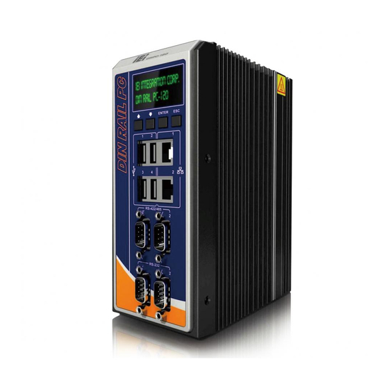
DRPC-120-BTi Embedded System MODEL: DRPC-120-BTi Fanless Embedded System with Intel® Atom™ E3845 CPU, DIN Rail Mounting Support, OLED Display or LED Indicators, Dual GbE, USB, DIO, Serial Ports, 9V~28V DC Power Input, RoHS Compliant User Manual Page i Rev. 1.00 – November 20, 2014... - Page 2 DRPC-120-BTi Embedded System Revision Date Version Changes November 20, 2014 1.00 Initial release Page ii...
- Page 3 DRPC-120-BTi Embedded System Copyright COPYRIGHT NOTICE The information in this document is subject to change without prior notice in order to improve reliability, design and function and does not represent a commitment on the part of the manufacturer. In no event will the manufacturer be liable for direct, indirect, special, incidental, or consequential damages arising out of the use or inability to use the product or documentation, even if advised of the possibility of such damages.
-
Page 4: Table Of Contents
DRPC-120-BTi Embedded System Table of Contents 1 INTRODUCTION......................1 1.1 O ........................2 VERVIEW 1.2 M ....................2 ODEL ARIATIONS 1.3 F ........................3 EATURES 1.4 C ....................4 ONNECTOR ANEL 1.4.1 Front Panel ......................4 1.4.2 Top Panel ......................5 1.5 LED I... - Page 5 DRPC-120-BTi Embedded System 3.9.4 RS-232 Serial Port Connectors (COM1, COM2) ..........30 3.9.5 RS-422/485 Serial Port Connectors (COM3, COM4) ........31 3.9.6 USB Connectors....................32 3.9.7 VGA Connector ....................33 3.10 IPMI S ..................33 ETUP ROCEDURE 3.10.1 Managed System Hardware Setup ..............34 3.10.2 Using the IEI iMAN Web GUI................
- Page 6 5.4.2.1 PCI Express Configuration ............... 68 5.5 S ......................... 69 ECURITY 5.6 B ........................70 5.7 E ......................... 72 6 PROGRAMMING OLED FOR DRPC-120-BTI-E5-OLED ........74 6.1 O ........................ 75 VERVIEW 6.2 OLED I ....................75 MAGE DITOR 6.2.1 OLED Image Editor Installation ..............75 6.2.2 Launching the OLED Image Editor..............
- Page 7 DRPC-120-BTi Embedded System 7.3 E ............93 XTERNAL NTERFACE ANEL ONNECTORS 7.3.1 Digital I/O Terminal Block (J1) ............... 94 7.3.2 Power Input Terminal Block (DC_IN1) ............94 7.3.3 RJ-45 LAN Connector (LAN1)................. 94 7.3.4 RJ-45 LAN Connector (LAN2)................. 95 7.3.5 RS-232 Serial Ports (COM1/2)................ 95 7.3.6 RS-422/485 Serial Ports (COM3/4)..............
- Page 8 DRPC-120-BTi Embedded System List of Figures Figure 1-1: DRPC-120-BTi Series ....................2 Figure 1-2: DRPC-120-BTi-E5-LED Front Panel................4 Figure 1-3: DRPC-120-BTi-E5-OLED Front Panel ................5 Figure 1-4: DRPC-120-BTi Top Panel....................6 Figure 1-5: LED Indicators of DRPC-120-BTi-E5-LED..............6 Figure 1-6: Physical Dimensions (millimeters)................10 Figure 3-1: Internal Access Panel Removal................18 Figure 3-2: HDD Installation ......................19...
- Page 9 DRPC-120-BTi Embedded System Figure 6-3: Confirm Installation ....................77 Figure 6-4: Installation Complete....................77 Figure 6-5: OLED Image Editor ....................78 Figure 6-6: Function List......................78 Figure 6-7: OLED Control ......................79 Figure 6-8: OLED Erase Page......................80 Figure 6-9: DR100 Demo Program Main Menu ................81 Figure 6-10: Dialog Menu......................82...
- Page 10 DRPC-120-BTi Embedded System List of Tables Table 1-1: DRPC-120-BTi Model Variations .................2 Table 1-2: DRPC-120-BTi-E5-LED LED Definitions ..............7 Table 1-3: Technical Specifications....................9 Table 3-1: DIO Terminal Block Pinouts ..................27 Table 3-2: LAN1 Pinouts ......................28 Table 3-3: LAN2 Pinouts ......................28 Table 3-4: RJ-45 Ethernet Connector LEDs ................28 Table 3-5: 3-pin Power Terminal Block Pinouts ................29...
- Page 11 DRPC-120-BTi Embedded System Table 7-17: Power Input Terminal Block (DC_IN1) Pinouts............94 Table 7-18: RJ-45 LAN Connector (LAN1) Pinouts ..............94 Table 7-19: RJ-45 LAN Connector (LAN2) Pinouts ..............95 Table 7-20: RS-232 Serial Port (COM1/2) Pinouts ..............95 Table 7-21: RS-422/485 Serial Port (COM3/4) Pinouts ..............95 Table 7-22: USB 2.0 Connectors (USB2) Pinouts..............96...
-
Page 13: Introduction
DRPC-120-BTi Embedded System Chapter Introduction Page 1... -
Page 14: Overview
It is designed for harsh environment applications, and supports DIN rail mounting method. The DRPC-120-BTi accepts a wide range of DC power input (9 V ~ 28 V), allowing it to be powered anywhere. Two USB 3.0, two USB 2.0, two GbE, two RS-232, two RS-422/485, and one 8-bit DIO provide rich I/O options for various applications. -
Page 15: Features
DRPC-120-BTi Embedded System 1.3 Features The DRPC-120-BTi features are listed below: 1.91 GHz quad-core Intel® Atom™ E3845 processor Low power consumption Fanless design DIN rail mounting support Preinstalled one 2 GB DDR3L SO-DIMM (system max. 8 GB) Supports one mSATA and one 2.5”... -
Page 16: Connector Panel
DRPC-120-BTi Embedded System 1.4 Connector Panel 1.4.1 Front Panel The DRPC-120-BTi front panel contains: 2 x RJ-45 Gigabit LAN ports 2 x RS-232 serial ports with isolation 2 x RS-422/485 serial ports with isolation 2 x USB 3.0 ports ... -
Page 17: Top Panel
DRPC-120-BTi Embedded System Figure 1-3: DRPC-120-BTi-E5-OLED Front Panel 1.4.2 Top Panel The DRPC-120-BTi top panel contains: 1 x 8-bit digital I/O (Phoenix terminal block, 4-bit input/4-bit output) 1 x 9 V ~ 28 V DC power terminal block ... -
Page 18: Led Indicators (Drpc-120-Bti-E5-Led Only)
DRPC-120-BTi Embedded System Figure 1-4: DRPC-120-BTi Top Panel 1.5 LED Indicators (DRPC-120-BTi-E5-LED Only) The LED indicators on the front panel of the DRPC-120-BTi-E5-LED are shown in Figure 1-5. Figure 1-5: LED Indicators of DRPC-120-BTi-E5-LED All the LED definitions are listed in Table 1-2. -
Page 19: Programmable Oled Display (Drpc-120-Bti-E5-Oled Only)
When the DIO is set to pull-low, the DIO LED indicators are always off. Table 1-2: DRPC-120-BTi-E5-LED LED Definitions 1.6 Programmable OLED Display (DRPC-120-BTi-E5-OLED Only) For programming the OLED display on the front panel of the DRPC-120-BTi-E5-OLED, refer to Chapter 6. 1.7 Technical Specifications The DRPC-120-BTi technical specifications are listed in Table 1-3. - Page 20 DRPC-120-BTi Embedded System Specifications Storage One 2.5” SATA 3Gb/s HDD/SSD bay One PCIe Mini full-size card slot for mSATA module mSATA (SATA 3Gb/s) I/O and Indicators 2 x RJ-45 ports Ethernet 2 x DB-9 serial ports with 3KV isolation protection...
-
Page 21: Table 1-3: Technical Specifications
DRPC-120-BTi Embedded System Specifications -20C~60C with air flow (with SSD) Operating Temperature -30C~70C Storage Temperature 5%~95%, non-condensing Humidity Extruded aluminum alloy for fanless support Chassis Construction Blue C + Black C Color Half-sine shock test 5G/11ms, 3 shocks per axis Operating Shock MIL-STD-810F 514.5 C-2 (SSD) -
Page 22: Dimensions
DRPC-120-BTi Embedded System 1.8 Dimensions The physical dimensions are shown below: Figure 1-6: Physical Dimensions (millimeters) Page 10... -
Page 23: Unpacking
DRPC-120-BTi Embedded System Chapter Unpacking Page 11... -
Page 24: Anti-Static Precautions
2.2 Unpacking Precautions When the DRPC-120-BTi is unpacked, please do the following: Follow the anti-static precautions outlined in Section 2.1. Make sure the packing box is facing upwards so the DRPC-120-BTi does not fall out of the box. ... -
Page 25: Unpacking Checklist
If some of the components listed in the checklist below are missing, please do not proceed with the installation. Contact the IEI reseller or vendor you purchased the DRPC-120-BTi from or contact an IEI sales representative directly. To contact an IEI sales representative, please send an email to sales@ieiworld.com... - Page 26 DRPC-120-BTi Embedded System Quantity Item and Part Number Image Standard Mounting bracket screw Screw (for securing an PCIe Mini card) One Key Recovery CD User manual and driver CD The following table lists the optional items that can be purchased separately.
- Page 27 DRPC-120-BTi Embedded System Optional Flash disk, mSATA, 2GB~32GB, 0C ~ 70C (P/N: IPE-5200IM-xxx) Flash disk, mSATA, 2GB~32GB, -40C ~ 85C (P/N: IPE-5200VM-xxx) Page 15...
-
Page 28: Installation
DRPC-120-BTi Embedded System Chapter Installation Page 16... -
Page 29: Installation Precautions
Air Circulation: Make sure there is sufficient air circulation when installing the DRPC-120-BTi. The DRPC-120-BTi’s cooling vents must not be obstructed by any objects. Blocking the vents can cause overheating of the DRPC-120-BTi. Leave at least 5 cm of clearance around the DRPC-120-BTi to prevent overheating. ... -
Page 30: Internal Access Panel Removal
Figure 3-1: Internal Access Panel Removal 3.3 HDD Installation The DRPC-120-BTi allows installation of one 2.5” HDD/SSD. To install a HDD into the system, please follow the steps below. Remove the internal access panel from the DRPC-120-BTi. Please follow the Step 1: instruction described in Section 3.2. -
Page 31: Msata Ssd Installation
Step 5: 3.4 mSATA SSD Installation The DRPC-120-BTi has one full-size PCIe Mini slot on the motherboard for mSATA SSD installation. To install the mSATA SSD, follow the instructions below. Remove the internal access panel from the DRPC-120-BTi. Please follow the Step 1: instruction described in Section 3.2. -
Page 32: Figure 3-3: Pcie Mini Slot Location
DRPC-120-BTi Embedded System Figure 3-3: PCIe Mini Slot Location Insert into the socket at an angle. Line up the notch on the card with the notch Step 3: on the connector. Slide the PCIe Mini card into the socket at an angle of about 20º... -
Page 33: Ipmi Module Installation (Optional)
Doing so may cause damage to the DRPC-120-BTi. Please follow the steps below to install the iRIS-2400 module, and refer to Section 3.10 for the setup procedure. Remove the internal access panel from the DRPC-120-BTi. Please follow the Step 1: instruction described in Section 3.2. -
Page 34: Figure 3-6: Ipmi Module Slot Location
DRPC-120-BTi Embedded System Figure 3-6: IPMI Module Slot Location Align the iRIS-2400 module with the IPMI module slot. Align the notch on the Step 3: module with the notch on the IPMI module slot. Insert the iRIS-2400 module. Push the module in at a 20º angle (Figure 3-7). -
Page 35: Clear Cmos
DRPC-120-BTi Embedded System 3.6 Clear CMOS If the DRPC-120-BTi fails to boot due to improper BIOS settings, the clear CMOS button clears the CMOS data and resets the system BIOS information. To do this, push the clear CMOS button for a few seconds. -
Page 36: At/Atx Mode Selection
DRPC-120-BTi Embedded System 3.7 AT/ATX Mode Selection AT and ATX power modes can both be used on the DRPC-120-BTi. The selection is made through an AT/ATX switch on the top panel as shown below (Figure 3-9). Figure 3-9: AT/ATX Switch Location 3.8 Mounting the System... -
Page 37: Figure 3-11: Attach The Mounting Bracket To The Din Rail
DRPC-120-BTi Embedded System NOTE: In the diagrams below, the DIN rail is already installed on a surface or on a chassis. Attach the upper edge of the mounting bracket to the DIN rail as shown in Step 2: Figure 3-11. -
Page 38: External Peripheral Interface Connectors
Push the system toward the DIN rail until the mounting bracket clips into place Step 3: firmly (Figure 3-12). Figure 3-12: Mounting the System 3.9 External Peripheral Interface Connectors The DRPC-120-BTi has the following connectors. Detailed descriptions of the connectors can be found in the subsections below. 8-bit DIO ... -
Page 39: Digital Input/Output Terminal Block
DRPC-120-BTi Embedded System 3.9.1 Digital Input/Output Terminal Block CN Label: Terminal block CN Type: See Figure 1-4 CN Location: See Table 3-1 and Figure 3-13 CN Pinouts: The digital I/O terminal block provides programmable input and output for external devices. -
Page 40: Figure 3-14: Rj-45 Ethernet Connector
DRPC-120-BTi Embedded System Description Description LAN1_MDI0P LAN1_MDI2P LAN1_MDI0N LAN1_MDI2N LAN1_MDI1P LAN1_MDI3P LAN1_MDI1N LAN1_MDI3N Table 3-2: LAN1 Pinouts Description Description TRD2P0 TRD2P2 TRD2N0 TRD2N2 TRD2P1 TRD2P3 TRD2N1 TRD2N3 Table 3-3: LAN2 Pinouts Figure 3-14: RJ-45 Ethernet Connector The RJ-45 Ethernet connector has two status LEDs, one green and one yellow. The green LED indicates activity on the port and the yellow LED indicates the port is linked. -
Page 41: Power Input, 3-Pin Terminal Block
DRPC-120-BTi Embedded System 3.9.3 Power Input, 3-pin Terminal Block 3-pin terminal block CN Type: See Figure 1-4 CN Location: See Table 3-5 and Figure 3-15 CN Pinouts: Connect the leads of a 9 V ~ 28 V DC power supply into the terminal block. Make sure that the power and ground wires are attached to the correct sockets of the connector. -
Page 42: Serial Port Connectors (Com1, Com2)
DRPC-120-BTi Embedded System 3.9.4 RS-232 Serial Port Connectors (COM1, COM2) COM1 and COM2 CN Label: DB-9 connectors CN Type: See Figure 1-2 CN Location: See Table 3-6 and Figure 3-16 CN Pinouts: RS-232 serial port devices can be attached to the DB-9 ports on the front panel. -
Page 43: Rs-422/485 Serial Port Connectors (Com3, Com4)
DRPC-120-BTi Embedded System 3.9.5 RS-422/485 Serial Port Connectors (COM3, COM4) COM3 and COM4 CN Label: DB-9 connectors CN Type: See Figure 1-2 CN Location: See Table 3-7 and Figure 3-17 CN Pinouts: RS-422/485 serial port devices can be attached to the DB-9 ports on the front panel. -
Page 44: Usb Connectors
DRPC-120-BTi Embedded System 3.9.6 USB Connectors USB port CN Type: See Figure 1-2 CN Location: See Table 3-8 and Table 3-9 CN Pinouts: The USB ports are for connecting USB peripheral devices to the system. The USB 2.0 and USB 3.0 connector pinouts are listed below. -
Page 45: Vga Connector
The DRPC-120-BTi features Intelligent Platform Management Interface (IPMI) that helps lower the overall costs of server management by enabling users to maximize IT resource, save time and manage multiple systems. The DRPC-120-BTi supports IPMI 2.0 through the optional iRIS-2400 module. Follow the steps below to setup IPMI. -
Page 46: Managed System Hardware Setup
DRPC-120-BTi Embedded System 3.10.1 Managed System Hardware Setup The hardware configuration of the managed system (DRPC-120-BTi) is described below. Install an iRIS-2400 module to the IPMI module socket (refer to Section 3.5). Step 1: Make sure at least one DDR3 SO-DIMM is installed in one of the SO-DIMM Step 2: sockets. -
Page 47: Figure 3-20: Iei Iman Web Gui
Figure 3-20: IEI iMAN Web GUI NOTE: To understand how to use the IEI iMAN Web GUI, please refer to the iRIS-2400 Web GUI user manual in the utility CD came with the DRPC-120-BTi. The user manual describes each function in detail. Page 35... -
Page 48: Driver Installation
Visit the IEI website or contact technical support for the latest updates. All the drivers for the DRPC-120-BTi are on the utility CD that came with the system. The utility CD contains drivers for Windows 7 and Windows 8 operating systems. Please select the corresponding drivers for the system. -
Page 49: System Maintenance
DRPC-120-BTi Embedded System Chapter System Maintenance Page 37... -
Page 50: System Maintenance Introduction
Before accessing any DRPC-120-BTi internal components, make sure all power to the system has been disconnected. Failing to do so may cause severe damage to the DRPC-120-BTi and injury to the user. WARNING! Please take antistatic precautions when working with the internal components. -
Page 51: So-Dimm Replacement
DRPC-120-BTi Embedded System 4.3 SO-DIMM Replacement To install/replace the SO-DIMM modules, please follow the steps below. Remove the internal access panel from the DRPC-120-BTi. Please follow the Step 1: instruction described in Section 3.2. Locate the SO-DIMM module on the motherboard. -
Page 52: Figure 4-2: So-Dimm Module Installation
DRPC-120-BTi Embedded System Figure 4-2: SO-DIMM Module Installation Push the new SO-DIMM module until it engages and the white plastic end clips Step 7: click into place. Make sure the end clips are fully secured after installation. Step 0: Page 40... -
Page 53: Bios
DRPC-120-BTi Embedded System Chapter BIOS Page 41... -
Page 54: Introduction
DRPC-120-BTi Embedded System 5.1 Introduction The BIOS is programmed onto the BIOS chip. The BIOS setup program allows changes to certain system settings. This chapter outlines the options that can be changed. NOTE: Some of the BIOS options may vary throughout the life cycle of the product and are subject to change without prior notice. -
Page 55: Getting Help
DRPC-120-BTi Embedded System Function Decrease the numeric value or make changes Esc key Main Menu – Quit and not save changes into CMOS Status Page Setup Menu and Option Page Setup Menu -- Exit current page and return to Main Menu... -
Page 56: Main
DRPC-120-BTi Embedded System The following sections completely describe the configuration options found in the menu items at the top of the BIOS screen and listed above. 5.2 Main The Main BIOS menu (BIOS Menu 1) appears when the BIOS Setup program is entered. - Page 57 DRPC-120-BTi Embedded System Core Version: Current BIOS version Compliancy: Current compliant version Project Version: the board version Build Date and Time: Date and time the current BIOS version was made iWDD Vendor: Installed embedded controller vendor iWDD Version: Current embedded controller version ...
-
Page 58: Advanced
DRPC-120-BTi Embedded System TXE Information The TXE Information lists a brief summary of Intel® Trusted Execution Engine (TXE). The fields in TXE Information cannot be changed. The items shown in the system overview include: Sec RC Version: Current sec reference code version ... -
Page 59: Acpi Settings
DRPC-120-BTi Embedded System Aptio Setup Utility – Copyright (C) 2013 American Megatrends, Inc. Main Advanced Chipset Security Boot Save & Exit > ACPI Settings System ACPI Parameters > Super IO Configuration > iWDD H/W Monitor > RTC Wake Settings > Serial Port Console Redirection ---------------------- >... -
Page 60: Super Io Configuration
DRPC-120-BTi Embedded System ACPI Sleep State [S3 (Suspend to RAM)] Use the ACPI Sleep State option to specify the sleep state the system enters when it is not being used. The caches are flushed and the CPU is powered... -
Page 61: Serial Port N Configuration
DRPC-120-BTi Embedded System 5.3.2.1 Serial Port n Configuration Use the Serial Port n Configuration menu (BIOS Menu 5) to configure the serial port n. Aptio Setup Utility – Copyright (C) 2013 American Megatrends, Inc. Advanced Serial Port n Configuration Enable or Disable Serial... - Page 62 DRPC-120-BTi Embedded System Serial Port I/O port address is 3F8h and the interrupt IO=3F8h; address is IRQ3, 4, 5, 6, 7, 9, 10, 11, 12 IRQ=3, 5, 6, 7, 9, 10, 11, 12 Serial Port I/O port address is 2F8h and the interrupt IO=2F8h;...
- Page 63 DRPC-120-BTi Embedded System Serial Port I/O port address is 2F8h and the interrupt IO=2F8h; address is IRQ3 IRQ=3 Serial Port I/O port address is 3F8h and the interrupt IO=3F8h; address is IRQ3, 4, 5, 6, 7, 9, 10, 11, 12...
- Page 64 DRPC-120-BTi Embedded System The serial port IO port address and interrupt address Auto EFAULT are automatically detected. Serial Port I/O port address is 3E8h and the interrupt IO=3E8h; address is IRQ7 IRQ=7 Serial Port I/O port address is 3F8h and the interrupt IO=3F8h;...
- Page 65 DRPC-120-BTi Embedded System 5.3.2.1.4 Serial Port 4 Configuration Serial Port [Enabled] Use the Serial Port option to enable or disable the serial port. Disable the serial port Disabled Enable the serial port Enabled EFAULT Change Settings [Auto] Use the Change Settings option to change the serial port IO port address and interrupt address.
-
Page 66: Iwdd H/W Monitor
DRPC-120-BTi Embedded System Serial Port I/O port address is 2F0h and the interrupt IO=2F0h; address is IRQ3, 4, 5, 6, 7, 9, 10, 11, 12 IRQ=3, 5, 6, 7, 9, 10, 11, 12 Serial Port I/O port address is 2E0h and the interrupt IO=2E0h;... -
Page 67: Smart Fan Mode Configuration
DRPC-120-BTi Embedded System System Temperatures: CPU Temperature System Temperature Fan Speed: CPU Fan Voltages: CPU_CORE +V12 +DDR +5VSB +3.3V +3.3VSB 5.3.3.1 Smart Fan Mode Configuration Use the Smart Fan Mode Configuration submenu (BIOS Menu 7) to configure smart fan temperature and speed settings. - Page 68 DRPC-120-BTi Embedded System The fan spins at the speed set in Manual Mode Manual Mode settings. The fan adjusts its speed using Auto Mode Auto Mode EFAULT settings. Auto mode fan start temperature Use the + or – key to change the Auto mode fan start temperature value. Enter a decimal number between 1 and 100.
-
Page 69: Rtc Wake Settings
DRPC-120-BTi Embedded System 5.3.4 RTC Wake Settings The RTC Wake Settings menu (BIOS Menu 8) configures RTC wake event. Aptio Setup Utility – Copyright (C) 2013 American Megatrends, Inc. Advanced Wake System with Fixed Time [Disabled] Enables or Disables system wake on alarm event. -
Page 70: Serial Port Console Redirection
DRPC-120-BTi Embedded System If selected, the following appears with values that Enabled can be selected: *Wake up every day *Wake up date *Wake up hour *Wake up minute *Wake up second After setting the alarm, the computer turns itself on from a suspend state when the alarm goes off. - Page 71 DRPC-120-BTi Embedded System Console Redirection [Disabled] Use Console Redirection option to enable or disable the console redirection function. Disabled the console redirection function Disabled EFAULT Enabled the console redirection function Enabled The following options are available in the Console Redirection Settings submenu when the Console Redirection option is enabled.
-
Page 72: Cpu Configuration
DRPC-120-BTi Embedded System Sets the data bits at 8. EFAULT Parity [None] Use the Parity option to specify the parity bit that can be sent with the data bits for detecting the transmission errors. No parity bit is sent with the data bits. - Page 73 DRPC-120-BTi Embedded System Aptio Setup Utility – Copyright (C) 2013 American Megatrends, Inc. Advanced CPU Configuration Number enabled, a VMM can utilize the additional Intel(R) Celeron(R) CPU E3845 @ 1.91GHz hardware capabilities CPU Signature 30679 provided by Vanderpool Microcode Patch Technology.
- Page 74 DRPC-120-BTi Embedded System Intel Virtualization Technology [Enabled] Use the Intel Virtualization Technology option to enable or disable virtualization on the system. When combined with third party software, Intel® Virtualization technology allows several OSs to run on the same system at the same time.
-
Page 75: Ide Configuration
DRPC-120-BTi Embedded System 5.3.7 IDE Configuration Use the IDE Configuration menu (BIOS Menu 11) to change and/or set the configuration of the SATA devices installed in the system. Aptio Setup Utility – Copyright (C) 2013 American Megatrends, Inc. Advanced IDE Configuration... -
Page 76: Usb Configuration
DRPC-120-BTi Embedded System 5.3.8 USB Configuration Use the USB Configuration menu (BIOS Menu 12) to read USB configuration information and configure the USB settings. Aptio Setup Utility – Copyright (C) 2013 American Megatrends, Inc. Advanced USB Configuration Enables Legacy USB support. -
Page 77: Chipset
DRPC-120-BTi Embedded System Legacy USB support disabled Disabled Legacy USB support disabled if no USB devices are Auto connected 5.4 Chipset Use the Chipset menu (BIOS Menu 13) to access the North Bridge and South Bridge subsystem configuration menus. -
Page 78: North Bridge
DRPC-120-BTi Embedded System 5.4.1 North Bridge Use the North Bridge menu (BIOS Menu 14) to configure the north bridge parameters. Aptio Setup Utility – Copyright (C) 2013 American Megatrends, Inc. Chipset Memory Information Total Memory 2048 MB (LPDDR3) DIMM1 2048 MB (LPDDR3) --------------------- : Select Screen... - Page 79 DRPC-120-BTi Embedded System Restore on AC Power Loss [Last State] Use the Restore on AC Power Loss BIOS option to specify what state the system returns to if there is a sudden loss of power to the system. ...
-
Page 80: Pci Express Configuration
DRPC-120-BTi Embedded System 5.4.2.1 PCI Express Configuration Use the PCI Express Configuration submenu (BIOS Menu 16) to configure the PCI Express slots. Aptio Setup Utility – Copyright (C) 2013 American Megatrends, Inc. Chipset PCI Express Configuration Enable or Disable the PCI... -
Page 81: Security
DRPC-120-BTi Embedded System 5.5 Security Use the Security menu (BIOS Menu 17) to set system and user passwords. Aptio Setup Utility – Copyright (C) 2013 American Megatrends, Inc. Main Advanced Chipset Security Boot Save & Exit Password Description Set Administrator Password If ONLY the Administrator’s password is set,... -
Page 82: Boot
DRPC-120-BTi Embedded System 5.6 Boot Use the Boot menu (BIOS Menu 18) to configure system boot options. Aptio Setup Utility – Copyright (C) 2013 American Megatrends, Inc. Main Advanced Chipset Security Boot Save & Exit Boot Configuration Select the keyboard... - Page 83 DRPC-120-BTi Embedded System Quiet Boot [Enabled] Use the Quiet Boot BIOS option to select the screen display when the system boots. Normal POST messages displayed Disabled OEM Logo displayed instead of POST messages Enabled EFAULT UEFI Boot [Disabled] Use the UEFI Boot option to enable or disable to boot from a UEFI device.
-
Page 84: Exit
DRPC-120-BTi Embedded System 5.7 Exit Use the Exit menu (BIOS Menu 19) to load default BIOS values, optimal failsafe values and to save configuration changes. Aptio Setup Utility – Copyright (C) 2013 American Megatrends, Inc. Main Advanced Chipset Security Boot Save &... - Page 85 DRPC-120-BTi Embedded System Save as User Defaults Use the Save as User Defaults option to save the changes done so far as user defaults. Restore User Defaults Use the Restore User Defaults option to restore the user defaults to all the setup options.
-
Page 86: Programming Oled For Drpc-120-Bti-E5-Oled
DRPC-120-BTi Embedded System Chapter Programming OLED for DRPC-120-BTi-E5-OLED Page 74... -
Page 87: Overview
DRPC-120-BTi Embedded System 6.1 Overview The DRPC-120-BTi-E5-OLED comes with two programmable OLED display utilities that allow users to program their own APIs to show information on the OLED screen in graphic and text formats. The two utilities are listed below. -
Page 88: Figure 6-1: Oled Image Editor Setup Wizard
DRPC-120-BTi Embedded System Figure 6-1: OLED Image Editor Setup Wizard Select a folder for OLED Image Editor Installation in Figure 6-2. Click Next to Step 4: continue. Figure 6-2: Select Installation Folder Page 76... -
Page 89: Figure 6-3: Confirm Installation
DRPC-120-BTi Embedded System The following screen appears. Click Next to confirm the installation. Step 5: Figure 6-3: Confirm Installation The system starts installing the OLED Image Editor. Step 6: When the OLED Image Editor is successfully installed, the following window Step 7: appears. -
Page 90: Launching The Oled Image Editor
DRPC-120-BTi Embedded System 6.2.2 Launching the OLED Image Editor To launch the OLED Image Editor, double click the OLED Image Editor icon on the desktop. Figure 6-5: OLED Image Editor 6.2.3 Function List The OLED Image Editor provides picture drawing function. Users can draw simple pictures on the Canvas. -
Page 91: Oled Control
DRPC-120-BTi Embedded System OPEN: Allows loading a 24-bit BMP file. The resolution of the 24-bit BMP file must be 128 x 64. SAVE: Allows saving as a BMP file. The file must be saved as 24-bit BMP with 128 x 64 resolution. -
Page 92: Oled Erase Page
DRPC-120-BTi Embedded System the indicated page number. When writing an image into the OLED module, the OLED Status field displays “The page is under writing. Please wait…”. Please be patient and wait for several seconds. When finished, “Write Page Done” is displayed. -
Page 93: Drpc100 Demo Program
DRPC-120-BTi Embedded System 6.3 DRPC100 Demo Program NOTE: Refer to the DRPC100-Matrix LED UART Protocol reference manual packaged in the driver CD for detailed setup. The DRPC100 Demo Program allows displaying information in text format. To launch the DRPC100, double click the DRPC100_OLED_DEMO file located in the DEMO APP folder of the driver CD. -
Page 94: Dialog Menu
DRPC-120-BTi Embedded System 6.3.1 Dialog Menu The Dialog menu allows users to clear the OLED screen, and get ID. Figure 6-10: Dialog Menu Get ID: Click to get ID. Clr OLED: Click to clear the OLED screen. ... -
Page 95: Lcd Menu
DRPC-120-BTi Embedded System 6.3.2 LCD Menu The LCD menu allows users to edit the text for displaying on the OLED screen of the system. Figure 6-11: LCD Menu Send: Click to send the input text to be displayed on the OLED display. -
Page 96: Demo Menu
DRPC-120-BTi Embedded System 6.3.3 DEMO Menu The DEMO menu lists the activities of the function keys. Click Close to return to the main menu. Figure 6-12: DEMO Menu Page 84... -
Page 97: Interface Connectors
DRPC-120-BTi Embedded System Chapter Interface Connectors Page 85... -
Page 98: Peripheral Interface Connectors
DRPC-120-BTi Embedded System 7.1 Peripheral Interface Connectors The DRPC-120-BTi embedded system motherboard comes with a number of peripheral interface connectors and configuration jumpers. The connector locations are shown in Table 7-1 and Figure 7-2. The Pin 1 locations of the on-board connectors are also indicated in the diagrams. -
Page 99: Internal Peripheral Connectors
Internal peripheral connectors are found on the motherboard and are only accessible when the motherboard is outside of the chassis. The table below shows a list of the peripheral interface connectors on the DRPC-120-BTi motherboard. Pinouts of these connectors can be found in the following sections. -
Page 100: Audio Line-Out Connector (Line_Out1)
DRPC-120-BTi Embedded System 7.2.1 Audio Line-out Connector (LINE_OUT1) PIN NO. DESCRIPTION SPK_R AUDIO_GND AUDIO_GND SPK_L Table 7-2: Audio Line-out Connector (LINE_OUT1) Pinouts 7.2.2 Audio Mic-in Connector (MIC_IN1) PIN NO. DESCRIPTION MIC_R AUDIO_GND AUDIO_GND MIC_L Table 7-3: Audio Mic-in Connector (MIC_IN1) Pinouts 7.2.3 Battery Connector (BAT1) -
Page 101: Cpu Fan Connector (Cpu_Fan1)
DRPC-120-BTi Embedded System 7.2.5 CPU Fan Connector (CPU_FAN1) PIN NO. DESCRIPTION FANIO Table 7-6: CPU Fan Connector (CPU_FAN1) Pinouts 7.2.6 OLED/LED Signal Connector (OLED1) PIN NO. DESCRIPTION PIN NO. DESCRIPTION +12V LED_SDA GPIO LED_SCL GPIO RESET# Table 7-7: OLED/LED Signal Connector (OLED1) Pinouts 7.2.7 PCIe Mini Card Slot –... -
Page 102: Pcie Mini Card Slot - Half Size (Mini-Pcie1)
DRPC-120-BTi Embedded System PIN NO. DESCRIPTION PIN NO. DESCRIPTION 1.5V SMBCLK PETN/SATA_TXN SMBDATA PETP/SATA_TXP USBD- USBD+ 1.5V VCC3 Table 7-8: PCIe Mini Card Slot – Full Size (M_PCIE1) Pinouts 7.2.8 PCIe Mini Card Slot – Half Size (MINI-PCIE1) PIN NO. -
Page 103: Sata 3Gb/S Connector (Sata1)
DRPC-120-BTi Embedded System PIN NO. DESCRIPTION PIN NO. DESCRIPTION SMBCLK PETN2 SMBDATA PETP2 USBD- USBD+ 1.5V VCC3 Table 7-9: PCIe Mini Card Slot – Half Size (MINI-PCIE1) Pinouts 7.2.9 SATA 3Gb/s Connector (SATA1) PIN NO. DESCRIPTION Table 7-10: SATA 3Gb/s Connector (SATA1) Pinouts... -
Page 104: Sata Power Connector (Sata_Pwr1)
DRPC-120-BTi Embedded System 7.2.10 SATA Power Connector (SATA_PWR1) PIN NO. DESCRIPTION 5V (supports 1A) Table 7-11: SATA Power Connector (SATA_PWR1) Pinouts 7.2.11 SPI Flash Connector (JSPI1) PIN NO. DESCRIPTION SPI_VCC SPI_CS SPI_SO_SW SPI_CLK_SW SPI_SI_SW Table 7-12: SPI Flash Connector (JSPI1) Pinouts 7.2.12 SPI Flash Connector - EC (JSPI2) -
Page 105: Usb Connector (Usb1)
DESCRIPTION USB_DATA- USB_DAT+ Table 7-14: USB Connector (USB1) Pinouts 7.3 External Interface Panel Connectors The table below lists the rear panel connectors on the DRPC-120-BTi motherboard. Pinouts of these connectors can be found in the following sections. Connector Type Label... -
Page 106: Digital I/O Terminal Block (J1)
DRPC-120-BTi Embedded System 7.3.1 Digital I/O Terminal Block (J1) PIN NO. DESCRIPTION PIN NO. DESCRIPTION DGI_0 DGO_0 DGI_1 DGO_1 DGI_2 DGO_2 DGI_3 DGO_3 Isolator GND Isolator Vin Table 7-16: Digital I/O Terminal Block (J1) Pinouts 7.3.2 Power Input Terminal Block (DC_IN1) PIN NO. -
Page 107: Lan Connector (Lan2)
DRPC-120-BTi Embedded System 7.3.4 RJ-45 LAN Connector (LAN2) PIN NO. DESCRIPTION PIN NO. DESCRIPTION TRD2P0 TRD2P2 TRD2N0 TRD2N2 TRD2P1 TRD2P3 TRD2N1 TRD2N3 Table 7-19: RJ-45 LAN Connector (LAN2) Pinouts 7.3.5 RS-232 Serial Ports (COM1/2) PIN NO. DESCRIPTION PIN NO. DESCRIPTION Table 7-20: RS-232 Serial Port (COM1/2) Pinouts 7.3.6 RS-422/485 Serial Ports (COM3/4) -
Page 108: Usb 2.0 Connectors (Usb2)
DRPC-120-BTi Embedded System 7.3.7 USB 2.0 Connectors (USB2) PIN NO. DESCRIPTION PIN NO. DESCRIPTION DATA- DATA- DATA+ DATA+ GROUND GROUND Table 7-22: USB 2.0 Connectors (USB2) Pinouts 7.3.8 USB 3.0 Connectors (USB1) PIN NO. DESCRIPTION PIN NO. DESCRIPTION USB_DATA- USB_DATA-... -
Page 109: Table 7-24: Vga Connector (Vga1) Pinouts
DRPC-120-BTi Embedded System HSYNC VSYNC DDCCLK Table 7-24: VGA Connector (VGA1) Pinouts Page 97... -
Page 110: A Safety Precautions
DRPC-120-BTi Embedded System Appendix Safety Precautions Page 98... -
Page 111: Safety Precautions
DRPC-120-BTi Embedded System A.1 Safety Precautions WARNING: The precautions outlined in this appendix should be strictly followed. Failure to follow these precautions may result in permanent damage to the DRPC-120-BTi. Please follow the safety precautions outlined in the sections that follow: A.1.1 General Safety Precautions... -
Page 112: Anti-Static Precautions
Electrostatic discharge (ESD) can cause serious damage to electronic components, including the DRPC-120-BTi. Dry climates are especially susceptible to ESD. It is therefore critical that whenever the DRPC-120-BTi is opened and any of the electrical components are handled, the following anti-static precautions are strictly adhered to. -
Page 113: Product Disposal
Please follow the national guidelines for electrical and electronic product disposal. A.2 Maintenance and Cleaning Precautions When maintaining or cleaning the DRPC-120-BTi, please follow the guidelines below. A.2.1 Maintenance and Cleaning Prior to cleaning any part or component of the DRPC-120-BTi, please read the details below. Page 101... -
Page 114: Cleaning Tools
Some components in the DRPC-120-BTi may only be cleaned using a product specifically designed for the purpose. In such case, the product will be explicitly mentioned in the cleaning tips. Below is a list of items to use when cleaning the DRPC-120-BTi. ... -
Page 115: B Digital I/O Interface
DRPC-120-BTi Embedded System Appendix Digital I/O Interface Page 103... -
Page 116: Introduction
DRPC-120-BTi Embedded System B.1 Introduction The DIO connector on the DRPC-120-BTi is interfaced to GPIO ports on the Super I/O chipset. The DIO has both 4-bit digital inputs and 4-bit digital outputs. The digital inputs and digital outputs are generally control signals that control the on/off circuit of external devices or TTL devices. -
Page 117: Assembly Language Sample 1
DRPC-120-BTi Embedded System B.2 Assembly Language Sample 1 AX, 6F08H ;setting the digital port as input AL low byte = value AH – 6FH Sub-function: AL – 9 :Set the digital port as OUTPUT :Digital I/O input value B.3 Assembly Language Sample 2 AX, 6F09H ;setting the digital port as output... -
Page 118: C Hazardous Materials Disclosure
DRPC-120-BTi Embedded System Appendix Hazardous Materials Disclosure Page 106... -
Page 119: Hazardous Materials Disclosure Table For Ipb Products Certified As Rohs Compliant Under 2002/95/Ec Without Mercury
DRPC-120-BTi Embedded System C.1 Hazardous Materials Disclosure Table for IPB Products Certified as RoHS Compliant Under 2002/95/EC Without Mercury The details provided in this appendix are to ensure that the product is compliant with the Peoples Republic of China (China) RoHS standards. The table below acknowledges the presences of small quantities of certain materials in the product, and is applicable to China RoHS only. - Page 120 DRPC-120-BTi Embedded System Part Name Toxic or Hazardous Substances and Elements Lead Mercury Cadmium Hexavalent Polybrominated Polybrominated (Pb) (Hg) (Cd) Chromium Biphenyls Diphenyl (CR(VI)) (PBB) Ethers (PBDE) Housing Display Printed Circuit Board Metal Fasteners Cable Assembly Fan Assembly Power Supply...
- Page 121 DRPC-120-BTi Embedded System 此附件旨在确保本产品符合中国 RoHS 标准。以下表格标示此产品中某有毒物质的含量符 合中国 RoHS 标准规定的限量要求。 本产品上会附有”环境友好使用期限”的标签,此期限是估算这些物质”不会有泄漏或突变”的 年限。本产品可能包含有较短的环境友好使用期限的可替换元件,像是电池或灯管,这些元 件将会单独标示出来。 部件名称 有毒有害物质或元素 铅 汞 镉 六价铬 多溴联苯 多溴二苯 醚 (Pb) (Hg) (Cd) (CR(VI)) (PBB) (PBDE) 壳体 显示 印刷电路板 金属螺帽 电缆组装 风扇组装 电力供应组装 电池 O: 表示该有毒有害物质在该部件所有物质材料中的含量均在 SJ/T11363-2006 标准规定的限量要求以下。 X: 表示该有毒有害物质至少在该部件的某一均质材料中的含量超出 SJ/T11363-2006 标准规定的限量要求。...
Need help?
Do you have a question about the DRPC-120-BTi and is the answer not in the manual?
Questions and answers