Table of Contents
Advertisement
Quick Links
Download this manual
See also:
User Manual
Advertisement
Table of Contents

Related Manuals for IEI Technology TANK-800


Summary of Contents for IEI Technology TANK-800
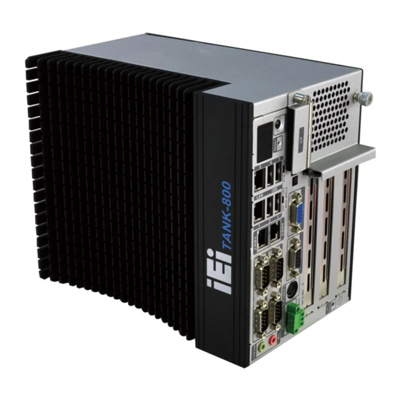
- Page 1 TANK-800 Embedded System MODEL: TANK-800 Fanless Embedded System with Intel® Atom™ D525 Dual Core CPU, VGA, Two Gigabit Ethernet, Four USB, RS-232/422/485, RoHS Compliant User Manual Page i Rev. 1.15 – September 10, 2015...
- Page 2 TANK-800 Embedded System Revision Date Version Changes September 10, 2015 1.15 Updated memory spec September 2, 2013 1.14 Updated Section 3.4: System Fan Installation April 2, 2013 1.13 Added the maximum dimensions of an expansion card in Section 1.7 February 5, 2013 1.12...
- Page 3 TANK-800 Embedded System Copyright COPYRIGHT NOTICE The information in this document is subject to change without prior notice in order to improve reliability, design and function and does not represent a commitment on the part of the manufacturer. In no event will the manufacturer be liable for direct, indirect, special, incidental, or consequential damages arising out of the use or inability to use the product or documentation, even if advised of the possibility of such damages.
- Page 4 TANK-800 Embedded System WARNING This device complies with Part 15 of the FCC Rules. Operation is subject to the following two conditions: (1) this device may not cause harmful interference, and(2) this device must accept any interference received, including interference that may cause undesired operation.
- Page 5 TANK-800 Embedded System Manual Conventions WARNING Warnings appear where overlooked details may cause damage to the equipment or result in personal injury. Warnings should be taken seriously. CAUTION Cautionary messages should be heeded to help reduce the chance of losing data or damaging the product.
-
Page 6: Table Of Contents
TANK-800 Embedded System Table of Contents 1 INTRODUCTION......................1 1.1 O ........................2 VERVIEW 1.2 M ....................3 ODEL ARIATIONS 1.3 F ........................3 EATURES 1.4 T ..................4 ECHNICAL PECIFICATIONS 1.5 C ....................6 ONNECTOR ANEL 1.6 LED I ....................... - Page 7 TANK-800 Embedded System 3.7.8 Power Input, 4-pin DIN Connector ..............32 3.7.9 RJ-45 RS-422/485 Serial Ports................ 33 3.7.10 RS-232 Serial Port Connectors..............35 3.7.11 USB Connectors ..................... 37 3.7.12 VGA Connector ....................38 3.8 P ................40 OWERING FF THE YSTEM 3.9 R...
- Page 8 TANK-800 Embedded System 4.4.1 Host Bridge Configuration ................68 4.4.2 South Bridge Configuration................68 4.4.3 Intel IGD SWSCI OpRegion................70 4.5 B ........................71 4.6 S ......................... 72 ECURITY 4.7 E ......................... 74 A REGULATORY COMPLIANCE ................76 B SAFETY PRECAUTIONS ..................81 B.1 S...
- Page 9 Figure 3-2: CF Card Slot Cover ....................18 Figure 3-3: CF Card Installation ....................19 Figure 3-4: Unscrew the Cover....................20 Figure 3-5: Remove the Cover from TANK-800 .................20 Figure 3-6: HDD Installation ......................21 Figure 3-7: HDD Retention Screws .....................21 Figure 3-8: Remove the HDD Bracket from the Cover ..............22 Figure 3-9: Remove the Fan Bracket from the Cover ...............23...
- Page 10 TANK-800 Embedded System Figure 3-25: DB-9 Connector Pinout Location ................35 Figure 3-26: Serial Device Connector..................36 Figure 3-27: Serial Port Pinout Location ..................36 Figure 3-28: USB Device Connection ..................37 Figure 3-29: VGA Connector .......................39 Figure 3-30: VGA Connector .......................39 Figure 3-31: Power Button......................40 Figure 3-32: Power Connectors ....................41...
- Page 11 TANK-800 Embedded System List of Tables Table 1-1: TANK-800 Model Variations..................3 Table 1-2: Technical Specifications....................5 Table 1-3: Supported Signals ......................8 Table 1-4: Rated Voltage and Current ..................9 Table 3-1: DIO Connector Pinouts ....................30 Table 3-2: LAN Pinouts ........................31 Table 3-3: RJ-45 Ethernet Connector LEDs ................32 Table 3-4: Power Input Pinouts ....................33...
-
Page 12: Introduction
TANK-800 Embedded System Chapter Introduction Page 1... -
Page 13: Overview
It is powered by the Intel® Atom™ D525 dual core processor, uses the Intel® ICH8M chipset and has 1.0 GB of DDR3 memory. The TANK-800 Series includes one VGA port, two PCIe GbE LAN, four USB 2.0 ports, and six COM ports. -
Page 14: Model Variations
TANK-800 Embedded System 1.2 Model Variations The model variations of the TANK-800 Series are listed below. Model No. Expansion Slots Intel® Atom™ D525 1.8 GHz Two PCI slots TANK-800-D525/1GB/2P1E-R10 dual core One PCIe x16 slot Intel® Atom™ D525 1.8 GHz... -
Page 15: Technical Specifications
TANK-800 Embedded System 1.4 Technical Specifications The TANK-800 technical specifications are listed in Table 1-2. Specifications System 1.8 GHz Intel® Atom™ D525 dual core CPU Intel® ICH8M Chipset On-board 1.0 GB DDR3 memory Memory 1 x 204-pin DDR3 SDRAM SO-DIMM slot (system max. 3.0 GB) Dual Realtek RTL8111E PCIe GbE controllers with ASF 2.0 support... -
Page 16: Table 1-2: Technical Specifications
TANK-800 Embedded System Specifications Power Redundant dual DC input 9V~36V Power Supply Power 1 (terminal block): 9 V (+/-0.3 V) ~ 36 V Power 2 (DC jack): 10.5 V (+/-0.3 V) ~ 36 V 33 W (without add-on card) Power Consumption... -
Page 17: Connector Panel
TANK-800 Embedded System 1.5 Connector Panel All external peripheral interface connectors are located on the rear panel of the TANK-800. The peripheral interface connectors are shown in Figure 1-2. Figure 1-2: TANK-800 Peripheral Connectors Connectors and buttons on the rear panel include the following. -
Page 18: Led Indicators
1 x ACC mode switch 1 x AT/ATX power mode switch 1.6 LED Indicators There are several indicators on the rear panel of the TANK-800 as shown in Figure 1-3. Figure 1-3: TANK-800 LED Indicators WARNING: The CPU Temperature Alert LED turns red when the CPU temperature is too high. -
Page 19: Backplane Options
TANK-800 Embedded System 1.7 Backplane Options The backplane options of the TANK-800 are shown below. Figure 1-4: TANK-800-D525/1GB/2P1E-R10 Backplane (HPE-3S6) Figure 1-5: TANK-800-D525/1GB/1P2E-R10 Backplane (HPE-3S7) The supported signals of the backplane slots are listed below. Backplane Slot Signal HPE-3S6 (2P1E) -
Page 20: Table 1-4: Rated Voltage And Current
TANK-800 Embedded System The rated voltage and current of the backplanes are listed below. Rated Voltage Rated Current +5 V +12 V 3.75 A -12 V 0.1 A +3.3 V Table 1-4: Rated Voltage and Current WARNING: The system default power is 96 W. The maximum total power of the backplane to support expansion cards is 45 W. -
Page 21: Dimensions
TANK-800 Embedded System 1.8 Dimensions The physical dimensions are shown below: Figure 1-6: Physical Dimensions (millimeters) Page 10... -
Page 22: Unpacking
TANK-800 Embedded System Chapter Unpacking Page 11... -
Page 23: Anti-Static Precautions
When the TANK-800 is unpacked, please do the following: Follow the anti-static precautions outlined in Section 2.1. Make sure the packing box is facing upwards so the TANK-800 does not fall out of the box. Make sure all the components shown in Section 2.3 are present. -
Page 24: Unpacking Checklist
If some of the components listed in the checklist below are missing, please do not proceed with the installation. Contact the IEI reseller or vendor you purchased the TANK-800 from or contact an IEI sales representative directly. To contact an IEI sales representative, please send an email to sales@ieiworld.com. - Page 25 TANK-800 Embedded System Quantity Item and Part Number Image Standard Mounting bracket (P/N: 41020-0308C2-00-RS) Mounting bracket screw (P/N: 44033-040062-RS) HDD screw (P/N: 44043-030051-RS) Rubber foot pad screw (P/N: 44005-030061-RS) Rubber foot pad (P/N: 46007-001500-RS) RJ-45 to DB-9 COM port cable...
- Page 26 TANK-800 Embedded System The following table lists the optional items that can be purchased separately. Optional System fan (P/N: 31100-000333-RS) OS: Win CE 6.0 (128MB CF Card) (P/N: TANKCF-800-D525-CE060-128M-R10) OS: Win XPE (2GB CF Card) (P/N: TANKCF-800-D525-XPE-2G-R10) OS: Win XPE (4GB CF Card)
-
Page 27: Installation
TANK-800 Embedded System Chapter Installation Page 16... -
Page 28: Installation Precautions
Electric shock and personal injury might occur if the rear panel of the TANK-800 is opened while the power cord is still connected to an electrical outlet. -
Page 29: Figure 3-1: Cf Card Slot
TANK-800 Embedded System Figure 3-1: CF Card Slot Open the CF card slot cover (Figure 3-2). Step 2: Figure 3-2: CF Card Slot Cover Page 18... -
Page 30: Hard Disk Drive (Hdd) Installation
TANK-800 Embedded System Correctly align the CF card with the socket and insert the CF card into the socket Step 3: (Figure 3-3). Figure 3-3: CF Card Installation Reinstall the cover. Step 4: 3.3 Hard Disk Drive (HDD) Installation To install the hard drive, please follow the steps below:... -
Page 31: Figure 3-4: Unscrew The Cover
TANK-800 Embedded System Figure 3-4: Unscrew the Cover Unplug the SATA signal and power cables connected to the TANK-800, and then Step 2: put the cover on a flat surface (Figure 3-5). Figure 3-5: Remove the Cover from TANK-800 Page 20... -
Page 32: Figure 3-6: Hdd Installation
TANK-800 Embedded System Attach the HDD to the HDD bracket, and then slide the HDD to connect the HDD Step 3: to the SATA connector (Figure 3-6). Figure 3-6: HDD Installation Secure the HDD with the HDD bracket by four retention screws (Figure 3-7). -
Page 33: System Fan Installation
Loosen the thumbscrew, slide the cover inwards (Figure 3-4), and then lift the Step 1: cover up gently. Unplug the SATA signal and power cables connected to the TANK-800, and then Step 2: place the cover on a flat surface (Figure 3-5). -
Page 34: Figure 3-9: Remove The Fan Bracket From The Cover
TANK-800 Embedded System Figure 3-9: Remove the Fan Bracket from the Cover Remove the temporary retaining bracket (Figure 3-10). Step 5: Figure 3-10: Remove the Temporary Retaining Bracket Attach the system fan to the fan bracket and secure it by four retention screws Step 6: (Figure 3-11). -
Page 35: Figure 3-11: Secure The System Fan To The Fan Bracket
Reinstall the HDD bracket to the cover. Step 8: Connect the system fan cable to the CPU_FAN1 connector on the motherboard Step 9: of TANK-800. Reconnect the SATA signal and power cables to the TANK-800. Step 10: Reinstall the cover. Step 11: Page 24... -
Page 36: Pluggable Dc-In Terminal Block Installation
TANK-800 Embedded System 3.5 Pluggable DC-In Terminal Block Installation To install the pluggable DC-in terminal block, please follow the steps below: Locate the DC-in terminal block connector. The location of the connector is Step 1: shown in Figure 1-2. Align the pluggable DC-in terminal block with the DC-in terminal block connector Step 2: on the TANK-800. -
Page 37: Mounting The System With Mounting Brackets
TANK-800 Embedded System 3.6 Mounting the System with Mounting Brackets To mount the embedded system onto a wall or some other surface using the two mounting brackets, please follow the steps below. Turn the embedded system over or to the left side panel. -
Page 38: External Peripheral Interface Connectors
Insert four retention screws, two in each bracket, to secure the system to the Step 6: wall. 3.7 External Peripheral Interface Connectors The TANK-800 has the following connectors. Detailed descriptions of the connectors can be found in the subsections below. Audio CompactFlash® Type II... -
Page 39: Acc Mode Selection
TANK-800 Embedded System 3.7.1 ACC Mode Selection The TANK-800 allows turning the ACC mode on or off. The setting can be made through the ACC mode switch on the external peripheral interface panel as shown below. Figure 3-15: ACC Mode Switch 3.7.2 AT/ATX Power Mode Selection... -
Page 40: Audio Connector
Microphone (Pink): Connects a microphone. Figure 3-17: Audio Connector 3.7.4 CompactFlash® Type II The TANK-800 has one CF Type II socket. The location of the socket is shown in Figure 1-2. To install the CF card, refer to Section 3.2. 3.7.5 Digital Input/Output Connector... -
Page 41: Lan Connectors
Locate the RJ-45 connectors. The locations of the RJ-45 connectors are Step 1: shown in Figure 1-2. Align the connectors. Align the RJ-45 connector on the LAN cable with one of Step 2: the RJ-45 connectors on the TANK-800. See Figure 3-19. Page 30... -
Page 42: Figure 3-19: Lan Connection
TANK-800 Embedded System Figure 3-19: LAN Connection Insert the LAN cable RJ-45 connector. Once aligned, gently insert the LAN Step 3: cable RJ-45 connector into the on-board RJ-45 connector. Description Description TRD1P0 TRD1P2 TRD1N0 TRD1N2 TRD1P1 TRD1P3 TRD1N1 TRD1N3 Table 3-2: LAN Pinouts Figure 3-20: RJ-45 Ethernet Connector The RJ-45 Ethernet connector has two status LEDs, one green and one yellow. -
Page 43: Power Input, 3-Pin Terminal Block
TANK-800 Embedded System Activity/Link LED Speed LED DESCRIPTION STATUS DESCRIPTION STATUS No link 10 Mbps connection Yellow Linked Green 100 Mbps connection Blinking TX/RX activity Orange 1 Gbps connection Table 3-3: RJ-45 Ethernet Connector LEDs 3.7.7 Power Input, 3-pin Terminal Block... -
Page 44: Rs-422/485 Serial Ports
RS-422/RS-485 connectors are shown in Figure 1-2. Insert the RJ-45 connector. Insert the RJ-45 connector on the RJ-45 to DB-9 Step 2: COM port cable to one of the RJ-45 RS-422/485 connectors on the TANK-800. See Figure 3-23. Page 33... -
Page 45: Figure 3-23: Rj-45 Rs-422/485 Serial Device Connection
TANK-800 Embedded System Figure 3-23: RJ-45 RS-422/485 Serial Device Connection Insert the serial connector. Insert the DB-9 connector of a serial device into Step 3: the DB-9 connector on the RJ-45 to DB-9 COM port cable. Secure the connector. Secure the serial device connector to the external Step 4: interface by tightening the two retention screws on either side of the connector. -
Page 46: Serial Port Connectors
TANK-800 Embedded System Figure 3-25: DB-9 Connector Pinout Location Description (RS-422) Description (RS-485) IRXD422+ IRXD422# ITXD422+ ITXD485+ ITXD422# ITXD485# Table 3-6: DB-9 Connector Pinouts 3.7.10 RS-232 Serial Port Connectors COM1, COM2, COM3 and COM4 CN Label: DB-9 connectors CN Type:... -
Page 47: Figure 3-26: Serial Device Connector
TANK-800 Embedded System Figure 3-26: Serial Device Connector Secure the connector. Secure the serial device connector to the external Step 3: interface by tightening the two retention screws on either side of the connector. Description Description Table 3-7: Serial Port Pinouts... -
Page 48: Usb Connectors
TANK-800 Embedded System 3.7.11 USB Connectors CN Label: USB port CN Type: See Figure 1-2 CN Location: See Table 3-8 CN Pinouts: The USB ports are for connecting USB peripheral devices to the system. Locate the USB connectors. The locations of the USB connectors are shown Step 1: in Figure 1-2. -
Page 49: Vga Connector
DB-15 connector on the external peripheral interface. Once the connectors are properly aligned with, Step 3: Insert the VGA connector. insert the male connector from the VGA screen into the female connector on the TANK-800. See Figure 3-29. Page 38... -
Page 50: Figure 3-29: Vga Connector
TANK-800 Embedded System Figure 3-29: VGA Connector Secure the connector. Secure the DB-15 VGA connector from the VGA Step 4: monitor to the external interface by tightening the two retention screws on either side of the connector. Figure 3-30: VGA Connector... -
Page 51: Powering On/Off The System
Figure 3-31: Power Button 3.9 Redundant Power The TANK-800 is a system that supports redundant power. The redundant power input increases the reliability of the system and prevents data loss and system corruption from sudden power failure. The system can instantly and uninterruptedly switch to the second power input when the main power is unavailable or in low voltage capacity. -
Page 52: Acc On
The ACC On mode is designed for vehicle applications. When the TANK-800 is in ACC On mode, the main power input is Power 1 connector and the backup power is from Power 2 connector. -
Page 53: Boot-Up
TANK-800 Embedded System 3.9.1.1 Boot-up When both power connectors are connected to power source with over 9 V power input, the two power LEDs on the front panel remain off until the ACC ON signal jump from low to high. The user can choose to use AT power mode or ATX power mode to control the system. -
Page 54: Shutdown
TANK-800 Embedded System Figure 3-35: ACC On: Switch Between PWR1 and PWR2 3.9.1.3 Shutdown The system will shutdown in the following situations: Power 1 < 9V and Power 2 < 10.5V Power 1 > 9V, Power 2 < 10.5V and ACC ON signal jump from high to low Press Power button for 6 seconds The following flow diagram shows the system shutdown process and the LED statuses. -
Page 55: Acc Off
TANK-800 Embedded System 3.9.2 ACC OFF When the TANK-800 is in ACC Off mode, the main power input is Power 2 connector and the backup power is from Power 1 connector. 3.9.2.1 Boot-up When both power connectors are connected to power source with over 9 V power input, the two power LEDs on the front panel turn on. -
Page 56: Shutdown
TANK-800 Embedded System Figure 3-39: ACC Off: Switch Between PWR1 and PWR2 3.9.2.3 Shutdown The system will shutdown in the following situations: Power 2 < 10.5V and Power 1 < 9V Press Power buttons for 6 seconds The following flow diagram shows the system shutdown process and the LED statuses. -
Page 57: Bios
TANK-800 Embedded System Chapter BIOS Page 46... -
Page 58: Introduction
TANK-800 Embedded System 4.1 Introduction The BIOS is programmed onto the BIOS chip. The BIOS setup program allows changes to certain system settings. This chapter outlines the options that can be changed. 4.1.1 Starting Setup The UEFI BIOS is activated when the computer is turned on. The setup program can be activated in one of two ways. -
Page 59: Getting Help
TANK-800 Embedded System Function Esc key Main Menu – Quit and not save changes into CMOS Status Page Setup Menu and Option Page Setup Menu -- Exit current page and return to Main Menu General help, only for Status Page Setup Menu and Option... -
Page 60: Main
TANK-800 Embedded System 4.2 Main The Main BIOS menu (BIOS Menu 1) appears when the BIOS Setup program is entered. The Main menu gives an overview of the basic system information. Aptio Setup Utility – Copyright (C) 2011 American Megatrends, Inc. -
Page 61: Advanced
TANK-800 Embedded System System Time [xx:xx:xx] Use the System Time option to set the system time. Manually enter the hours, minutes and seconds. 4.3 Advanced Use the Advanced menu (BIOS Menu 2) to configure the CPU and peripheral devices through the following sub-menus:... -
Page 62: Acpi Settings
TANK-800 Embedded System 4.3.1 ACPI Settings The ACPI Settings menu (BIOS Menu 3) configures the Advanced Configuration and Power Interface (ACPI) options. Aptio Setup Utility – Copyright (C) 2011 American Megatrends, Inc. Advanced ACPI Sleep State [S1 (CPU Stop Clock)]... -
Page 63: Cpu Configuration
TANK-800 Embedded System 4.3.2 CPU Configuration Use the CPU Configuration menu (BIOS Menu 4) to view detailed CPU specifications and configure the CPU. Aptio Setup Utility – Copyright (C) 2011 American Megatrends, Inc. Advanced CPU Configuration Enabled for Windows XP... -
Page 64: Ide Configuration
TANK-800 Embedded System Hyper-Threading: Indicates if the Intel Hyper-Threading Technology is supported by the CPU. Hyper-Threading [Enabled] Use the Hyper-Threading BIOS option to enable or disable the Intel Hyper-Threading Technology. Disables the Intel Hyper-Threading Technology. Disabled Enables the Intel Hyper-Threading Technology. - Page 65 TANK-800 Embedded System Configures the on-board ATA/IDE controller to be in Compatible compatible mode. In this mode, a SATA channel will replace one of the IDE channels. This mode supports up to 4 storage devices. Configures the on-board ATA/IDE controller to be in...
-
Page 66: Usb Configuration
TANK-800 Embedded System 4.3.4 USB Configuration Use the USB Configuration menu (BIOS Menu 6) to read USB configuration information and configure the USB settings. Aptio Setup Utility – Copyright (C) 2011 American Megatrends, Inc. Advanced USB Configuration Enables Legacy USB support. -
Page 67: Super Io Configuration
TANK-800 Embedded System Legacy USB support disabled Disabled Legacy USB support disabled if no USB devices are Auto connected 4.3.5 Super IO Configuration Use the Super IO Configuration menu (BIOS Menu 7) to set or change the configurations for the serial ports. -
Page 68: Serial Port N Configuration
TANK-800 Embedded System 4.3.5.1 Serial Port n Configuration Use the Serial Port n Configuration menu (BIOS Menu 8) to configure the serial port n. Aptio Setup Utility – Copyright (C) 2011 American Megatrends, Inc. Advanced Serial Port n Configuration Enable or Disable Serial... - Page 69 TANK-800 Embedded System Serial Port I/O port address is 3F8h and the interrupt IO=3F8h; address is IRQ3, 4 IRQ=3, 4 Serial Port I/O port address is 2F8h and the interrupt IO=2F8h; address is IRQ3, 4 IRQ=3, 4 Serial Port I/O port address is 2C0h and the interrupt IO=2C0h;...
- Page 70 TANK-800 Embedded System Serial Port I/O port address is 2C8h and the interrupt IO=2C8h; address is IRQ3, 4 IRQ=3, 4 4.3.5.1.3 Serial Port 3 Configuration Serial Port [Enabled] Use the Serial Port option to enable or disable the serial port.
- Page 71 TANK-800 Embedded System 4.3.5.1.4 Serial Port 4 Configuration Serial Port [Enabled] Use the Serial Port option to enable or disable the serial port. Disable the serial port Disabled Enable the serial port Enabled EFAULT Change Settings [Auto] Use the Change Settings option to change the serial port IO port address and interrupt address.
- Page 72 TANK-800 Embedded System 4.3.5.1.5 Serial Port 5 Configuration Serial Port [Enabled] Use the Serial Port option to enable or disable the serial port. Disable the serial port Disabled Enable the serial port Enabled EFAULT Change Settings [Auto] Use the Change Settings option to change the serial port IO port address and interrupt address.
- Page 73 TANK-800 Embedded System Disable the serial port Disabled Enable the serial port Enabled EFAULT Change Settings [Auto] Use the Change Settings option to change the serial port IO port address and interrupt address. The serial port IO port address and interrupt address...
-
Page 74: H/W Monitor
TANK-800 Embedded System 4.3.6 H/W Monitor The H/W Monitor menu (BIOS Menu 9) shows the operating temperature, fan speeds and system voltages. Aptio Setup Utility – Copyright (C) 2011 American Megatrends, Inc. Advanced PC Health Status CPU Temperature :+45 C Accuracy: 1. -
Page 75: Serial Port Console Redirection
TANK-800 Embedded System Vcc3S Vcc5V VSB3V VBAT 4.3.7 Serial Port Console Redirection The Serial Port Console Redirection menu (BIOS Menu 10) allows the console redirection options to be configured. Console redirection allows users to maintain a system remotely by re-directing keyboard input and text output through the serial port. - Page 76 TANK-800 Embedded System Enabled the console redirection function Enabled Terminal Type [VT-100+] Use the Terminal Type option to specify the remote terminal type. The target terminal type is VT100 VT100 The target terminal type is VT100+ VT100+ The target terminal type is VT-UTF8...
-
Page 77: Iei Feature
TANK-800 Embedded System 4.3.8 iEi Feature Use the iEi Feature menu (BIOS Menu 11) to configure the iEi features. Aptio Setup Utility – Copyright (C) 2011 American Megatrends, Inc. Advanced iEi Feature Auto Recovery Function Reboot and recover Auto Recovery Function... -
Page 78: Chipset
TANK-800 Embedded System 4.4 Chipset Use the Chipset menu (BIOS Menu 12) to access the Northbridge and Southbridge configuration menus. WARNING! Setting the wrong values for the Chipset BIOS selections in the Chipset BIOS menu may cause the system to malfunction. -
Page 79: Host Bridge Configuration
TANK-800 Embedded System 4.4.1 Host Bridge Configuration Tthe Host Bridge Configuration menu (BIOS Menu 13) shows the memory frequency and memory capacity. Aptio Setup Utility – Copyright (C) 2011 American Megatrends, Inc. Chipset ******* Memory Information ******* Memory Frequency 800 Mhz... - Page 80 TANK-800 Embedded System Restore AC Power Loss [Last State] Use the Restore AC Power Loss BIOS option to specify what state the system returns to if there is a sudden loss of power to the system. The system remains turned off...
-
Page 81: Intel Igd Swsci Opregion
TANK-800 Embedded System The spread spectrum mode is disabled Disabled EFAULT The spread spectrum mode is enabled Enabled 4.4.3 Intel IGD SWSCI OpRegion Use the Intel IGD SWSCI OpRegion menu (BIOS Menu 15) to configure the video device connected to the system. -
Page 82: Boot
TANK-800 Embedded System 128 MB 256 MB Maximum Default 4.5 Boot Use the Boot menu (BIOS Menu 16) to configure system boot options. Aptio Setup Utility – Copyright (C) 2011 American Megatrends, Inc. Main Advanced Chipset Boot Security Save & Exit... -
Page 83: Security
TANK-800 Embedded System Does not enable the keyboard Number Lock automatically. To use the 10-keys on the keyboard, press the Number Lock key located on the upper left-hand corner of the 10-key pad. The Number Lock LED on the keyboard lights up when the Number Lock is engaged. - Page 84 TANK-800 Embedded System Aptio Setup Utility – Copyright (C) 2011 American Megatrends, Inc. Main Advanced Chipset Boot Security Save & Exit Password Description Set Setup Administrator Password If ONLY the Administrator’s password is set, then this only limits access to Setup and is only asked for when entering Setup.
-
Page 85: Exit
TANK-800 Embedded System 4.7 Exit Use the Exit menu (BIOS Menu 18) to load default BIOS values, optimal failsafe values and to save configuration changes. Aptio Setup Utility – Copyright (C) 2011 American Megatrends, Inc. Main Advanced Chipset Boot Security Save &... - Page 86 TANK-800 Embedded System Save as User Defaults Use the Save as User Defaults option to save the changes done so far as user defaults. Restore User Defaults Use the Restore User Defaults option to restore the user defaults to all the setup options.
-
Page 87: A Regulatory Compliance
TANK-800 Embedded System Appendix Regulatory Compliance Page 76... - Page 88 TANK-800 Embedded System DECLARATION OF CONFORMITY This equipment is in conformity with the following EU directives: EMC Directive 2004/108/EC Low-Voltage Directive 2006/95/EC RoHS II Directive 2011/65/EU Ecodesign Directive 2009/125/EC If the user modifies and/or install other devices in the equipment, the CE conformity declaration may no longer apply.
- Page 89 TANK-800 Embedded System Español [Spanish] IEI Integration Corp declara que el equipo cumple con los requisitos esenciales y cualesquiera otras disposiciones aplicables o exigibles de la Directiva 1999/5/CE. Ελληνική [Greek] IEI Integration Corp ΔΗΛΩΝΕΙ ΟΤΙ ΕΞΟΠΛΙΣΜΟΣ ΣΥΜΜΟΡΦΩΝΕΤΑΙ ΠΡΟΣ ΤΙΣ ΟΥΣΙΩΔΕΙΣ ΑΠΑΙΤΗΣΕΙΣ ΚΑΙ ΤΙΣ ΛΟΙΠΕΣ ΣΧΕΤΙΚΕΣ ΔΙΑΤΑΞΕΙΣ ΤΗΣ ΟΔΗΓΙΑΣ...
- Page 90 TANK-800 Embedded System Româna [Romanian] IEI Integration Corp declară că acest echipament este in conformitate cu cerinţele esenţiale şi cu celelalte prevederi relevante ale Directivei 1999/5/CE. Slovensko [Slovenian] IEI Integration Corp izjavlja, da je ta opreme v skladu z bistvenimi zahtevami in ostalimi relevantnimi določili direktive 1999/5/ES.
- Page 91 TANK-800 Embedded System FCC WARNING This equipment complies with Part 15 of the FCC Rules. Operation is subject to the following two conditions: This device may not cause harmful interference, and This device must accept any interference received, including interference that may cause undesired operation.
-
Page 92: B Safety Precautions
TANK-800 Embedded System Appendix Safety Precautions Page 81... -
Page 93: Safety Precautions
TANK-800 Embedded System B.1 Safety Precautions WARNING: The precautions outlined in this appendix should be strictly followed. Failure to follow these precautions may result in permanent damage to the TANK-800. Please follow the safety precautions outlined in the sections that follow: B.1.1 General Safety Precautions... -
Page 94: Anti-Static Precautions
Electrostatic discharge (ESD) can cause serious damage to electronic components, including the TANK-800. Dry climates are especially susceptible to ESD. It is therefore critical that whenever the TANK-800 is opened and any of the electrical components are handled, the following anti-static precautions are strictly adhered to. -
Page 95: Product Disposal
When maintaining or cleaning the TANK-800, please follow the guidelines below. B.2.1 Maintenance and Cleaning Prior to cleaning any part or component of the TANK-800, please read the details below. The interior of the TANK-800 does not require cleaning. Keep fluids away from the TANK-800 interior. -
Page 96: Cleaning Tools
In such case, the product will be explicitly mentioned in the cleaning tips. Below is a list of items to use when cleaning the TANK-800. C loth – Although paper towels or tissues can be used, a soft, clean piece of cloth is recommended when cleaning the TANK-800. -
Page 97: C Digital I/O Interface
TANK-800 Embedded System Appendix Digital I/O Interface Page 86... -
Page 98: Introduction
TANK-800 Embedded System C.1 Introduction The DIO connector on the TANK-800 is interfaced to GPIO ports on the Super I/O chipset. The DIO has both 4-bit digital inputs and 4-bit digital outputs. The digital inputs and digital outputs are generally control signals that control the on/off circuit of external devices or TTL devices. -
Page 99: Assembly Language Sample 1
TANK-800 Embedded System C.2 Assembly Language Sample 1 AX, 6F08H ;setting the digital port as input AL low byte = value AH – 6FH Sub-function: AL – 9 :Set the digital port as OUTPUT :Digital I/O input value C.3 Assembly Language Sample 2 AX, 6F09H ;setting the digital port as output... -
Page 100: D Hazardous Materials Disclosure
TANK-800 Embedded System Appendix Hazardous Materials Disclosure Page 89... -
Page 101: Hazardous Materials Disclosure Table For Ipb Products Certified As Rohs Compliant Under 2002/95/Ec Without Mercury
TANK-800 Embedded System D.1 Hazardous Materials Disclosure Table for IPB Products Certified as RoHS Compliant Under 2002/95/EC Without Mercury The details provided in this appendix are to ensure that the product is compliant with the Peoples Republic of China (China) RoHS standards. The table below acknowledges the presences of small quantities of certain materials in the product, and is applicable to China RoHS only. - Page 102 TANK-800 Embedded System Part Name Toxic or Hazardous Substances and Elements Lead Mercury Cadmium Hexavalent Polybrominated Polybrominated Biphenyls Diphenyl (Pb) (Hg) (Cd) Chromium (CR(VI)) (PBB) Ethers (PBDE) Housing Display Printed Circuit Board Metal Fasteners Cable Assembly Fan Assembly Power Supply...
- Page 103 TANK-800 Embedded System 此附件旨在确保本产品符合中国 RoHS 标准。以下表格标示此产品中某有毒物质的含量符 合中国 RoHS 标准规定的限量要求。 本产品上会附有”环境友好使用期限”的标签,此期限是估算这些物质”不会有泄漏或突变”的 年限。本产品可能包含有较短的环境友好使用期限的可替换元件,像是电池或灯管,这些元 件将会单独标示出来。 部件名称 有毒有害物质或元素 铅 汞 镉 六价铬 多溴联苯 多溴二苯 醚 (Pb) (Hg) (Cd) (CR(VI)) (PBB) (PBDE) 壳体 显示 印刷电路板 金属螺帽 电缆组装 风扇组装 电力供应组装 电池 O: 表示该有毒有害物质在该部件所有物质材料中的含量均在 SJ/T11363-2006 标准规定的限量要求以下。 X: 表示该有毒有害物质至少在该部件的某一均质材料中的含量超出 SJ/T11363-2006 标准规定的限量要求。...
Need help?
Do you have a question about the TANK-800 and is the answer not in the manual?
Questions and answers