Table of Contents
Advertisement
iCAP Customer Training Manual
iCAP 6000 Series ICP-OES Spectrometer
Customer Training and Maintenance Manual
Version 1 - March 2009
© 2009 Thermo Electron Corporation Registration No. 441506
Stafford House, Boundary Way, Hemel Hempstead, HP2 7GE
http://www.thermo.com
United Kingdom. Telephone +44 (0) 1442 233555 ,
Advertisement
Table of Contents

Related Manuals for Thermo Scientific iCAP 6000 Series


Summary of Contents for Thermo Scientific iCAP 6000 Series
- Page 1 Customer Training Manual iCAP 6000 Series ICP-OES Spectrometer Customer Training and Maintenance Manual Version 1 - March 2009 © 2009 Thermo Electron Corporation Registration No. 441506 Stafford House, Boundary Way, Hemel Hempstead, HP2 7GE http://www.thermo.com United Kingdom. Telephone +44 (0) 1442 233555 ,...
-
Page 2: Table Of Contents
iCAP Customer Training Manual Contents Introduction........................3 Check Led indicators ....................3 Preparing the System for Use..................4 Instrument Shut-down....................4 Sample Introduction Glassware Assembly................5 Torch Assembly ......................5 Spray Chamber assembly ....................10 Final assembly ......................11 Attaching sample and drain tubing ................13 Autosampler Use......................15 Introduction .........................15 Autosampler Installation....................15 Autosampler Set-up ....................15 iTEVA Familiarisation ......................16... -
Page 3: Introduction
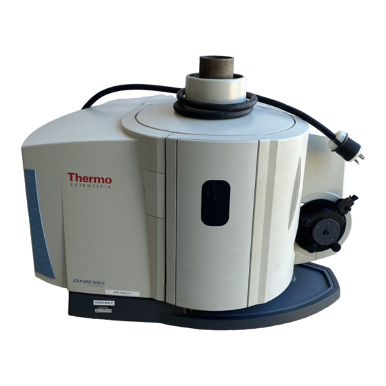
iCAP Customer Training Manual Introduction The iCAP 6000 is designed to be constantly powered up and the optical system continuously purged. The instrument is powered via an on/off switch at the rear of the left side. Figure 1 – iCAP 6000 Power On/Off Check Led indicators On the rear right hand side of instrument there are row of Led’s which indicate, when power on and the status of the instrument. -
Page 4: Preparing The System For Use
iCAP Customer Training Manual Preparing the System for Use If the gas supplies have been switched off, the optical components should be purged for at least one hour before powering the instrument. If the instrument is switched off, allow at least two hours after restoring power to thermally stabilise the instrument before the chiller is turned on. -
Page 5: Sample Introduction Glassware Assembly
iCAP Customer Training Manual Sample Introduction Glassware Assembly Warning: Appropriate care and safety procedures should be followed to avoid breaking any glassware and causing injury to the operator. Broken glassware should be handled with appropriate care. 2.1 Torch Assembly Figure 1 Duo Torch Assembly – Metal Torch Mount Figure 2 Radial Torch Assembly –... - Page 6 iCAP Customer Training Manual Correct Incorrect Figure 4 Torch Assembly – torch body Figure 5 Torch Assembly – centre tube Insert the centre tube (ground glass joint) fully into the centre tube holder. Figure 6 Torch Assembly – centre tube insertion Insert the centre tube assembly into the metal holder.
- Page 7 iCAP Customer Training Manual Figure 7 Torch Assembly – centre tube insertion Screw the centre tube assembly into the metal holder. Figure 8 Torch Assembly –spray chamber adaptor Insert the spray chamber adaptor (ground glass joint) into the rear of the centre tube holder...
- Page 8 iCAP Customer Training Manual Figure 9 Torch assembly holder Make sure metal holder is turned and locked in position.
- Page 9 iCAP Customer Training Manual Figure 10 – Torch Holder Push the torch assembly up into the holder and twist to lock.
-
Page 10: Spray Chamber Assembly
iCAP Customer Training Manual Spray Chamber assembly Start by connecting the drain tubing as figured below Figure 11 – Spray chamber drain Insert drain tube connector until it meets the main chamber. Figure 12 – Nebuliser to Spray Chamber The O-rings in the spray chamber should be inspected and replaced if any wear, or damage, is visible. -
Page 11: Final Assembly
iCAP Customer Training Manual 2.2 Final assembly Duo Spray chamber Figure 13 – Duo Spray chamber assembly Attach the swan neck fitting to the Spray chamber with the fitting clamp provided. The swan neck provided with the instrument is specially designed to prevent UV radiation from escaping from the torch box. - Page 12 iCAP Customer Training Manual For Radial Connect spray chamber and nebuliser assembly to the torch assembly as figure below Figure 15 – Radial Sample Introduction setup The torch compartment door must be closed before use.
-
Page 13: Attaching Sample And Drain Tubing
iCAP Customer Training Manual After assembly of the sample introduction system and prior to ignition of the plasma a check should be made for correct assembly :- Make sure the torch is fully rotated and locked in place. Make sure the centre tube holder is fully rotated and locked into the torch. Make sure the spray chamber connector is fully pushed into the torch body. - Page 14 iCAP Customer Training Manual Pass the drain capillary tubing through the lower holder in the cover and towards the pump. This holder contains a sensor detecting bubbles produced when the spray chamber is draining normally. The plasma and the pump will be switched off after 2 minutes if no bubbles are detected.
-
Page 15: Autosampler Use
iCAP Customer Training Manual 3 Autosampler Use 3.1 Introduction The autosampler can be configured to suit an application, or several applications. The volume, number and type of sample will all influence the set-up of the autosampler. 3.2 Autosampler Installation To comply with safety and warranty requirements the iCAP 6000, accessories and associated equipment must be installed by a Thermo Fisher trained and certified engineer. -
Page 16: Iteva Familiarisation
iCAP Customer Training Manual 4 iTEVA Familiarisation 4.1 Introduction The iCAP 6000 will require optimisation that is dependent on the sample being analysed and the method requirements. It is important that the method development verifies the data produced by the method. It is also important that a suitable quality control regime is established that verifies the continuing validity of data. - Page 17 iCAP Customer Training Manual Type admin in user name field and click on OK or press enter 4.3.2 Striking the Plasma Click on the Plasma Icon and then make sure the interlock indicators all show green, click on Plasma On. After the plasma strikes, wait until the Spectrometer Optimization is completed and then click on the close box Note: To allow the plasma to stabilise leave Plasma...
- Page 18 iCAP Customer Training Manual Click on Method tab as shown Click on Analysis Preferences Set Parameters as required (see iTEVA software manual for fuller explanation of the various parameters that can be selected) Note: The parameters shown will be a good starting point for an Analysis Click on Automated Output and fill in the relevant boxes Note: Make sure you tick save results to database...
- Page 19 iCAP Customer Training Manual 4.3.4 Running the Analysis Put the sample uptake tube in the blank solution. Click on the Analysis tab and then click on the Calibration Icon, click on Run in the Calibration box this will then analyze the blank solution Display of Blank solution results showing the Elements selected in the method setup.
- Page 20 iCAP Customer Training Manual Display of the Results page Save the Method if required by clicking on Method drop down menu and Save As, filling in the appropriate name. 4.3.5 Shutting down the system Place the sample tube in Deionised water and let it pump through the system for 3 to 5 minutes.
- Page 21 iCAP Customer Training Manual 4.3.6 Autosampler Operation First edit the Sequence Automation page of the method you plan to use. Then save the method. Click on Sequence tab at bottom of page Select New Autosampler on the Auto-Session Menu. This will pop up the dialog box shown.
- Page 22 iCAP Customer Training Manual The autosampler position tray will be displayed. Right click on the session name and select Auto-Locate this will then highlight the sample and standard positions. Note: Make sure the Plasma is ignited Click on the Autosampler connect icon as shown. Click on Run icon Image of Autosampler showing progress of sample run.
- Page 23 iCAP Customer Training Manual 4.3.7 Local Database Creation Click on TOOLS/OPTIONS on iTEVA control panel. Click on Application Database Tab Click on, Run database wizard box...
- Page 24 iCAP Customer Training Manual Type .\iTEVA in Server Name box Type sa in User Name box Type teva in Password box Click on Test connection box This should fill in the Server type and Server version boxes Click on Create box Enter required name for Database click OK and click on close box...
- Page 25 iCAP Customer Training Manual 4.3.8 Creating a Database Connection Click on the add a connection box as shown Type .\iTEVA in server name box Type sa in User name box Type teva in Password box From the, Select the database on the server box choose the Database required Click on test Connection Click OK...
- Page 26 iCAP Customer Training Manual The newly created database will now appear in the list of databases Select the created database form the Active connection drop down box and click on OK This will now make the new database active 4.3.9 Attaching a database After running data base wizard click on Attach Click on Database Filename/Log Filename Select database to Attach...
- Page 27 iCAP Customer Training Manual 4.3.11 Backing up databases Click on, Run database wizard box Type .\iTEVA in server name box Type sa in User name box Type teva in Password box Click on Backup Select database name from drop down list Click OK Choose path for Backup and click OK Click Yes...
-
Page 28: Maintenance
iCAP Customer Training Manual 4.3.12 Restoring a database From Data base wizard select Restore and carry out the same procedure as Backup database above 5 Maintenance 5.1 Introduction The iCAP 6000 has been designed for minimum maintenance; however the sample introduction components should be checked regularly for contamination and wear. -
Page 29: Purged Optical Path Window Cleaning
iCAP Customer Training Manual To remove salt deposits wash the torch in an ultrasonic bath for five minutes in a dilute surfactant. To remove metallic deposits from the tip, separate the torch quartz section, immerse the tip of the torch in hot acid (a mixture of nitric and hydrochloric similar to Aqua Regia is suitable) After cleaning, rinse the torch with de-ionised water and place in a drying oven at 95º... -
Page 30: Analytical Problems Hints And Tips
iCAP Customer Training Manual 6 Analytical Problems Hints and Tips Poor Precision Before jumping to any conclusions, a quick test should be run to determine if the poor analytical results are matrix related. A 10 ppm solution of a few common elements such as Cu, Mn, Ba, Cd, Zn and Fe should be put together and a method made using the primary lines. - Page 31 iCAP Customer Training Manual glass or Teflon chamber the chamber should be wetted properly; that is there should be no water droplets building up on the walls of the spray chamber. This is usually caused by an oily film and can be easily cured by aspirating a 0.1% HF acid solution for about 20 seconds.
- Page 32 iCAP Customer Training Manual Less prone to clogging are the high solids nebuliser designs, such as the Babington or V-Groove but orientation is critical as the sample is gravity fed across the argon orifice for atomisation. Note: Two spacing rings to be used at all times...
- Page 33 iCAP Customer Training Manual 6.1.1.1 Teflon capillary tubing: Should be free of kinks and scissor or pinch cut ends. For best results, razor cut at 45° for the drain. Also check the sample peristaltic pump winding condition and platen pressure for proper adjustment. Replace the winding if it is used or collapsed.
-
Page 34: Poor Accuracy/Feedback
iCAP Customer Training Manual 6.2 Poor accuracy/feedback First we should define accuracy as reproducing the standard value once standardised Proceed by making a standard as in the previous section (10 ppm Cu, Mn, Cd, Zn, Fe) and using this as the test solution. Remember we are not defining accuracy for this test as the ability to read a 1 or 100 ppm standard after standardising on the 10 ppm. -
Page 35: Suggested Maintenance In The Case Of Poor Precision And Detection Limits
iCAP Customer Training Manual 8 Suggested maintenance in the case of poor precision and detection limits 8.1 Introduction Maintenance refers to a series of periodic activities that should be performed on a periodic basis to optimise the short term and long term performance of the system. In this chapter we describe activities that should be performed by the typical user of the instrument. -
Page 36: Preventing Blocking Of The Nebuliser
iCAP Customer Training Manual 8.4 Preventing blocking of the nebuliser The most common problem with the nebuliser is the blockage of the tip by the deposition of particulate matter. In this section we provide a series of suggestions to minimise blockage. In most instances blockage in the nebuliser is caused by either particulate matter (from the sample) - Page 37 iCAP Customer Training Manual Tip: Rinse the nebuliser. It is very important to rinse the nebuliser before turning the gas off. It is advisable to rinse the nebuliser periodically throughout the sequence (depending on the chemistry of your samples). Solids may be deposited in the nozzle as sample solvent evaporates, further constricting the flow passages and reducing the signal.
-
Page 38: Removing The Concentric Glass Nebuliser
iCAP Customer Training Manual 8.5 Removing the concentric glass nebuliser Remove the sample capillary by pulling the small white Teflon stopper that attaches it to the back of the nebuliser. Remove the nebuliser carefully out of the spray chamber using a rotation motion at the same time as pulling it out. - Page 39 iCAP Customer Training Manual Force isopropyl alcohol backwards through the nozzle in an attempt to float the particle out through the larger gas and liquid input tubes. Use a squeeze bottle or plastic dropper with a tip that will form a good seal over the nebuliser nozzle. After the particle has been removed, remove the alcohol through the input tubes using compressed gas, or drain onto lint-free tissue.
-
Page 40: Cleaning The Glass Mixing Chamber
iCAP Customer Training Manual 8.6.5 Plugged capillary (fusible solids e.g. waxes) Note: This procedure should be used when no passage remains through the deposit. Carefully heat the nebuliser in the region of the capillary obstruction. Simultaneously (or intermittently) apply gentle gas pressure at the sample input tube. Caution: Avoid overheating residues that may produce insoluble pyrolysis products Stop treatment when you have opened a passage through the blockage. -
Page 41: Notes
iCAP Customer Training Manual 9 Notes...
Need help?
Do you have a question about the iCAP 6000 Series and is the answer not in the manual?
Questions and answers