Table of Contents
Advertisement
Quick Links
Advertisement
Table of Contents

Related Manuals for CD Automation REVO C 2PH 1100A


Summary of Contents for CD Automation REVO C 2PH 1100A
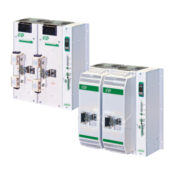
- Page 1 USER’S MANUAL Rev. 05/2022 EXTENDED Solid-State Relay 1100A - 1400A 1600A - 1800A - 2100A M-RC2-1100-2100 CD Automation S.r.l. Via Picasso, 34/36 - 20025 Legnano (MI)- Italy Tel. +39 0331 577479 - Fax +39 0331 579479 E-mail: info@cdautomation.com - Web: www.cdautomation.com...
-
Page 2: Declaration Of Conformity
P.I. 08925720156 -Tel. +39 0331 577479 - Fax +39 0331 579479 E-mail: info@cdautomation.com - Web: www.cdautomation.com Declare that the product / Dichiara che il prodotto: REVO C 2PH 1100A-1400A-1600A-1800A-2100A PRODUCT DESCRIPTION: Electric power control SCOPE OF APPLICATION: Thermal control process DESCRIZIONE DEL PRODOTTO: Unità... - Page 3 P.I. 08925720156 -Tel. +39 0331 577479 - Fax +39 0331 579479 E-mail: info@cdautomation.com - Web: www.cdautomation.com Declare that the product / Dichiara che il prodotto: REVO C 2PH 1100A-1400A-1600A-1800A-2100A PRODUCT DESCRIPTION: Electric power control SCOPE OF APPLICATION: Thermal control process DESCRIZIONE DEL PRODOTTO: Unità...
-
Page 4: Important Warnings For Safety
User’s manual REVO C 2PH from 1100A to 2100A Important warnings for safety This chapter contains important information for the safety. The not observance of these instructions may result in serious personal injury or death and can cause serious damages to the Thyristor unit and to the components system included. - Page 5 User’s manual REVO C 2PH from 1100A to 2100A WARNING! All service including inspection, installation, wiring, maintenance, troubleshooting, fuse or other user serviceable component replacement must be performed only by properly qualified personnel. Service personnel must read this manual before proceeding with work. While service is being performed unqualified personnel should not work on the unit or be allowed in the immediate vicinity.
- Page 6 User’s manual REVO C 2PH from 1100A to 2100A AVERTISSEMENT! Au moment de relever des mesures de tension ou de courant en direct, utiliser un équipement de protection individuelle approprié pour les tensions et les potentiels d’arc électrique concernés. WARNING! Verify the voltage and current ratings of the power controller are correct for the application. AVERTISSEMENT! Vérifier que les valeurs de tension et de courant du régulateur de puissance sont correctes pour l’application.
-
Page 7: Maintenance
Substituted parts remain of Producer property. CD Automation srl assumes no liability for any damage to persons or property deriving from tampering, from incorrect or improper use, or from any use not conforming to the characteristics of the controller and to the instructions in this User Manual. -
Page 8: Table Of Contents
User’s manual REVO C 2PH from 1100A to 2100A Summary Declaration of conformity....... . .2 Important warnings for safety . - Page 9 User’s manual REVO C 2PH from 1100A to 2100A Using the Configurator ....... . . 54 10.1 Typical Uses .
-
Page 10: Introduction
User’s manual REVO C 2PH from 1100A to 2100A Introduction A thyristor unit is semiconductor device which acts as a switch formed by two thyristors in antiparallel. To switch on the alternating current the input signal will be on and the thyristor will switch off at first Zero Crossing voltage with no input signal. -
Page 11: Advantages Compared With Analog Thyristor Unit
User’s manual REVO C 2PH from 1100A to 2100A Advantages compared with analog thyristor unit Communication RS485 is a standard feature of REVO C this allows the use of many information like: current, power, load state and all the parameters for diagnostic and configuration. Ulterior advantages of the digital system vs the analogical is the flexibility and the possibility of implement special characteristics without change the hardware. -
Page 12: Software Configurator
User’s manual REVO C 2PH from 1100A to 2100A Software Configurator Thyristor configurator software is free and is possible download it from our site. If the Order Code is in line with requirement, then unit has been already configured in Factory and it’s ready to use. -
Page 13: Quick Start
User’s manual REVO C 2PH from 1100A to 2100A Quick Start Attention: this procedure must be carried out by skilled people only. If your REVO C code is in line with what you really need, then the main configuration is already done by Producer and you just need to do the following steps: Verify REVO C current sizing. -
Page 14: Basic Connections And Sizing
User’s manual REVO C 2PH from 1100A to 2100A Basic Connections and sizing Star wiring with resistive load I= P 1,73V V = Nominal voltage of the load I = Nominal current of the load P = Nominal power of the load Delta wiring with resistive load I= P 1,73V... -
Page 15: Identification And Order Code
User’s manual REVO C 2PH from 1100A to 2100A Identification and Order Code 5.1 Identification of the unit Caution: Before to install, make sure that the Thyristor unit have not damages. If the product has a fault, please contact the dealer from which you purchased the product. The identification’s label give all the information regarding the factory settings of the Thyristor unit, this label is on the unit, like represented in figure. - Page 16 User’s manual REVO C 2PH from 1100A to 2100A 5.1.1 Order code REVO C 2PH CURRENT FUSES OPTION description description code description code 1100A Fixed Fuses Included No Option 1400A Fixed Fuses Included Option code - see table . . . 1600A Fixed Fuses Included 1800A...
- Page 17 Option that allows communication with a smart phone. From your smart WiFi phone via the CD Automation App, direct to your thyristor unit in the cabinet to read current, voltage, power and energy totalization as well as the ability to change parameters to improve process and product quality without opening the cabinet door.
-
Page 18: Technical Specifications
User’s manual REVO C 2PH from 1100A to 2100A Technical Specifications 6.1 General features Operative voltage: 480V +10% max -10% min 600V +10% max -10% min 690V +10% max -10% min Utilization Category: AC-51 IP Code: 00 (IP20 on request) Method of Connecting: Load in Delta, Load in Star Auxiliary voltage:... -
Page 19: Output Features 690V
User’s manual REVO C 2PH from 1100A to 2100A 6.4 Output features 690V Repetitive FUSE I2T Output Power peak value FANS Voltage Latching Max peak Leakage Frequency loss Current reverse Suggested (230Vac Standard) range current one cycle current range Thyristor voltage A2s (at (115Vac Option) -
Page 20: Calculating Flow Capacity Of The Fan
User’s manual REVO C 2PH from 1100A to 2100A 6.7 Calculating flow capacity of the fan All the thyristor units when are in conduction produces power loss that is dissipated inside cubicle in terms of heating. Due to this fact the internal temperature of cubicle is higher than ambient temperature. To be cooled the thyristor need of fresh air cooling and to do it is normally used a fan mounted on the front door or on the roof of the cabinet. -
Page 21: Installation
User’s manual REVO C 2PH from 1100A to 2100A Installation Before to install, make sure that the Thyristor unit have not damages. AIR FLOW OUT (V) If the product has a fault, please contact the dealer from which you purchased the product. Verify that the product is the same thing as ordered. -
Page 22: Dimensions And Weight
User’s manual REVO C 2PH from 1100A to 2100A 7.1 Dimensions and Weight Size: SR 19 - 2PH 1100A Size: SR22 - 2PH 1400A-1600A-1800A-2100A H: 550 mm, W: 523 mm, D: 347 mm H: 730 mm, W: 523 mm, D: 347 mm Weight: 49 Kg Weight: 65 Kg Standard version with IP0... -
Page 23: Fixing Holes
User’s manual REVO C 2PH from 1100A to 2100A 7.2 Fixing holes 1100A A: 217,5 mm 12,5 12,5 1400A-1600A-1800A-2100A A: 267,5 mm 6 X M8... -
Page 24: Lifting The Unit
User’s manual REVO C 2PH from 1100A to 2100A 7.3. Lifting the unit • take all necessary safety precautions • use safety shoes and clothing • do not keep lifted for longer than strictly necessary... -
Page 25: Wiring Instructions
User’s manual REVO C 2PH from 1100A to 2100A Wiring instructions The Thyristor unit could be susceptible to interferences lost by near equipments or by the power supply, for this reason in accord to the fundamental practices rules is opportune take some precautions: •... -
Page 26: Power Terminals
User’s manual REVO C 2PH from 1100A to 2100A 8.2 Power Terminals Warning: Before connecting or disconnecting the unit check that power and control cables are isolated from voltage sources. Description Terminal Line Input Phase 1 Line Input Phase 2 Load Output Phase 1 Load Output Phase 2 A: 124mm... - Page 27 User’s manual REVO C 2PH from 1100A to 2100A 4 x Hole D9mm 4 x Hole D9mm 68,5 36,5 273,5 1100A A: 315mm B: 220mm 1400A-1600A-1800A-2100A A: 365mm B: 270mm...
-
Page 28: Ip20 Cover Option
User’s manual REVO C 2PH from 1100A to 2100A 8.3 IP20 Cover OPTION 6.3.1 Removing the IP20 cover For each phase: *1 Unscrew the two bottom M6 screws. *2 Pull out the bottom cover. *3 Unscrew the two upper M6 screws. *4 Pull out the upper cover. -
Page 29: Power Cable Dimensions (Suggested)
User’s manual REVO C 2PH from 1100A to 2100A 8.4 Power cable dimensions (suggested) Supply Load Current Bar type Screw M Bar type Screw M 1100A Bus Bar: 2x 50x6mm 4xM8 Bus Bar: 2x 50x6mm 4xM8 1400A-1600A Bus Bar: 2x 50x10mm 4xM8 Bus Bar: 2x 50x10mm 4xM8... -
Page 30: Cable Dimensions (Suggested) Of Earth And Of The Command Terminals
User’s manual REVO C 2PH from 1100A to 2100A 8.5 Cable dimensions (suggested) of Earth and of the Command Terminals Earth Command Terminals Current Cable Screw Cable mm² mm² 1100A 0,50 1400A 0,50 1600A-2100A 2x95 2x3/0 0,50 G+G- K+ K- G+G- K+ K- 220V... -
Page 31: Commmand Terminals
User’s manual REVO C 2PH from 1100A to 2100A 8.6 Commmand Terminals Warning: Before connecting or disconnecting the unit check that power and control cables are isolated from voltage sources. 8.6.1 Terminal M5 Terminal Description NO - Normally Open contact alarm relay output (HB in alarm/GENERAL in alarm) C - Common contact alarm relay output (HB/GENERAL) NC - Normally Close contact alarm relay output (HB in alarm/GENERAL in alarm) + Analog Input 2 (0-10Vdc/4-20mA Analog Setpoint) - Page 32 User’s manual REVO C 2PH from 1100A to 2100A 8.6.3 Terminal MX 1-2 Terminal Description Internal Connection (G+) Internal Connection (K+) Internal Connection (G-) Internal Connection (K-) Internal Connection (Current Transformer) Internal Connection (Current Transformer) Internal Connection (Fuse fault Switch) Internal Connection (Fuse fault Switch) Internal Connection (Fan fault Switch) Internal Connection (Fan fault Switch)
-
Page 33: Fan Supply For Each Phase (Mx1 - Mx2)
User’s manual REVO C 2PH from 1100A to 2100A 8.7 Fan Supply For Each Phase (MX1 – MX2) Terminal Description Fan supply voltage (230V standard – 115 option) Fan supply voltage (230V standard – 115 option) 1 2 3 4 5 6 7 8 9 10 11 12 13 14 15 16 8.8 Thermal Switch For Each Phase (MX1 –... -
Page 34: Schematic
User’s manual REVO C 2PH from 1100A to 2100A 8.9 Schematic Caution: this procedure must be performed only by qualified persons. Option Ethernet Profibus Branch Circuit Protection Sync Micro USB +24V IN Auxiliary Second Microprocessor +24Vdc Retransmit SYNC voltage supply thermal switch power &... - Page 35 User’s manual REVO C 2PH from 1100A to 2100A Caution: this procedure must be performed only by qualified persons. Indicative connection diagrams. Refer to local regulations for proper system protection. Option +24V IN +24V IN +24V IN RETRANS RETRANS RETRANS OUT: OUT: OUT:...
- Page 36 User’s manual REVO C 2PH from 1100A to 2100A Load Type Delta Star 8.9.1 SSR Control Input schematic For SSR input use follow the schematic below and configure Digital Input 1 as Fast Enable. Analog Input 1 INPUT * SSR Input: 4÷30Vdc 5mA Max (ON >4Vdc / OFF <1Vdc) Frequency 3Hz Max - On time min.
-
Page 37: Connection Diagram For 3 Phases (Control On 2 Phases)
User’s manual REVO C 2PH from 1100A to 2100A 8.10 Connection Diagram for 3 phases (control on 2 phases) SYNC Voltage Supply Not connected Voltage Supply HB Relay Alarm General Alarm Unit Analog Input 2 ENABLE Conf. Input / SSR RS485+ RS485- +10V... -
Page 38: Control Panel
User’s manual REVO C 2PH from 1100A to 2100A Control Panel The Control Panel is placed on the front of the thyristor unit, on his display you can visualize the alarms, the input and output signals and all the configuration parameters. Iout0.0A Vout0.0V Pout0%... -
Page 39: Menu Navigation
User’s manual REVO C 2PH from 1100A to 2100A 9.1 Menu navigation The menus are accessible using the control panel keypad and display. Choose Enter Choose Edit HOME PAGE Menu Password Parameter Parameter Iout0.0A Password Set Point Iout0.0A 100% SP 100% Iout0.0A Set Point Menu... -
Page 40: Control Panel Led
User’s manual REVO C 2PH from 1100A to 2100A 9.2 Control Panel Led The four indicators on the control panel show the general state of the power controller. Flashing Power output set locally or via communications Local/Remote Power output set remotely (via analog input) Aux High SP 100% Output enabled... -
Page 41: Parameter List
User’s manual REVO C 2PH from 1100A to 2100A 9.4 Parameter list This chapter describes the parameter on the menus accessed via the control panel and Configurator software. To learn how to access the menus described below see “Menu navigation” chapter. Menu Listing The table below lists the parameters found on each menu. - Page 42 User’s manual REVO C 2PH from 1100A to 2100A 9.4.1 Operator Menu This section describes each item on the operator menu. Use this menu to view the measured values and basic settings of the power controller. The password to access this menu is 0. Modbus Par.
- Page 43 User’s manual REVO C 2PH from 1100A to 2100A 9.4.2 Setup Menu This section describes each item on the setup menu. Use this menu to configure the power controller for the load. The password to access this menu is 2. Modbus Par.
- Page 44 User’s manual REVO C 2PH from 1100A to 2100A 9.4.3 Advanced Setup Menu This section describes each item on the advanced setup menu. Use this menu to configure the power switching, closed loop control of power and adjustable settings for data logging and heater bakeout. The password to access this menu is 10.
- Page 45 User’s manual REVO C 2PH from 1100A to 2100A Modbus Par. Parameter Name Description Default Range Unit Address Type Pb Power Set the gain for the main loop. A larger Read value yields a larger adjustment for a 0 to 255 Write given deviation Ti Power...
- Page 46 User’s manual REVO C 2PH from 1100A to 2100A 9.4.4 Hardware Menu This section describes each item on the hardware menu. Use this menu to configure how the inputs and outputs are used in the application. The password to access this menu is 5. Modbus Par.
- Page 47 User’s manual REVO C 2PH from 1100A to 2100A Modbus Par. Parameter Name Description Default Address Type DI1 Functn Choose how the signal detected by digital input 1 Read is used Write Option Description Value Enable Enable power output V Feedback Use voltage feed-back when on Local / Rmt Local when on / Remote when off...
- Page 48 User’s manual REVO C 2PH from 1100A to 2100A Modbus Par. Parameter Name Description Default Address Type Alm Out Fn Choose for which conditions the digital output indicates alarm. The output always indicate an alarm when the heat sink is over temperature. The digital output is energized for normal operating condition and de-energized when the power Read...
- Page 49 User’s manual REVO C 2PH from 1100A to 2100A Modbus Par. Parameter Name Description Default Range Unit Address Type Rtx Scale value retransmitted parameter to be represented by the Read 0 to 9999 full scale of the analog output. See Write the table below Recommended...
- Page 50 User’s manual REVO C 2PH from 1100A to 2100A 9.4.5 Communication Menu This section describes each item on the communication menu. Use this menu to configure the communication options. The password to access this menu is 3. Modbus Par. Parameter Name Description Default Address...
- Page 51 User’s manual REVO C 2PH from 1100A to 2100A Modbus Par. Parameter Name Description Default Range Unit Address Type WD Reset Set the amount of time to wait for Read communication message before 0 to 255 Write triggering the watchdog error Wi-Fi Addr Indicate the IP address of the WiFi 94-95...
- Page 52 User’s manual REVO C 2PH from 1100A to 2100A 9.4.6 Monitoring Menu This section describes each item on the monitoring menu. Use this menu to view the states of digital input, values of analog input and information about the power controller such as serial number and software version. The password to access this menu is 0.
- Page 53 User’s manual REVO C 2PH from 1100A to 2100A Modbus Par. Parameter Name Description Address Type SP Source Indicate whether the power controller is local or remote set Read 14 bit1 point mode Only Option Description Value Local / Comms Set Point via keypad or communication Remote Set Point via analog input...
-
Page 54: Using The Configurator
User’s manual REVO C 2PH from 1100A to 2100A Using the Configurator Confi gurator software can be used like an alternative of the power controller’s keypad and set the advanced features not available via the power controller’s onboard user interface. Here we explain how to use it. - Page 55 User’s manual REVO C 2PH from 1100A to 2100A Procedure to communicate with a power controller: 1) if used direct USB connection: - Connect the USB cable between the computer and the micro USB connector on the power controller’s keypad - if necessary, Wait for the USB driver to install.
-
Page 56: Using The Configurator
User’s manual REVO C 2PH from 1100A to 2100A 10.5 Using the Confi gurator After software has been installed, communication has been set up and model type selected, is possible operate with power controller. 10.5.1 To view or save a power controller’s settings using “Simple”... - Page 57 User’s manual REVO C 2PH from 1100A to 2100A 10.5.3 To download a recipe fi le into a power controller: 1) Click Simple, if not already on the Simple view 2) Click Open existing recipe 3) Locate and select the recipe fi le and click Open 4) Click 5) Click...
- Page 58 User’s manual REVO C 2PH from 1100A to 2100A 10.5.8 To reset the power totals: 1) Click Test, if not already on the test view 2) Click Online 3) Click Reset Totals 4) Click 10.5.9 Setting Up and Using Data Logging To set up data logging: 1) Click Test, if not already on the test view 2) Click...
-
Page 59: Software General Information
User’s manual REVO C 2PH from 1100A to 2100A 10.5.10 To retrieve a data log fi le from the power controller: 1) Click Test, if not already on the test view 2) Click Online 3) Click Load Analyzer 4) Click Connect 5) Select a fi le from the list 6) Click... - Page 60 User’s manual REVO C 2PH from 1100A to 2100A 10.6.2 Simple Section This section is used to create, save, upload and download recipes of parameters settings. Can be used also to see the settings in a controller. Simple page is the default page when select the model using the Model Button, but If not selected is possible access it clicking the Simple tab below the main menu.
- Page 61 User’s manual REVO C 2PH from 1100A to 2100A 10.6.3 Test Section This section is used to monitor and adjust the operation of the power controller in real time using RS485 or USB communication port. After select the model, is possible access to this section clicking the “TEST”...
- Page 62 User’s manual REVO C 2PH from 1100A to 2100A Buttons setup options: Firing: view and set the fi ring type and the associated parameters Feedback: view and set feedback type Communication: view and set communication options for ports, protocols and fi eldbus Confi gure and monitor the analog inputs: Analog Input 1: click Ai 1 to view the signal type...
- Page 63 User’s manual REVO C 2PH from 1100A to 2100A 10.6.4. Load Analyzer Load Analyzer is used for monitoring values graphically represent Click on Load Analyzer button on the test page will open Load Analyzer window. Is possible see 3 channels (Ch 1, Ch 2 and Ch 3). For each channel confi gure a pen on the graph: On/Off...
- Page 64 User’s manual REVO C 2PH from 1100A to 2100A 10.6.5 Data Log Window In the power controller the data log window is used to manage fi les and set up logging parameter like log interval time and date/time in rtc Log Enabled/Log Disabled slider: Enable and disable data logging function.
- Page 65 User’s manual REVO C 2PH from 1100A to 2100A 10.6.7 MSG view Message view display the communication activity between the computer and the power controller. PORT COM: use this view to see when the COM port is accessed and its settings MODBUS: Modbus communication protocol area READ Area: use this view to see parameters...
-
Page 66: Configurable Inputs And Outputs
User’s manual REVO C 2PH from 1100A to 2100A Configurable inputs and Outputs The REVO C power controller features two digital inputs, up to two analog inputs and a relay output. Some models also include an analog output for retransmitting a measured value to other automation equipment. This section describes the various functions of these inputs and outputs and how they interact with other features of the power controller. -
Page 67: Analog Input 2: Set Point Or Feedback
User’s manual REVO C 2PH from 1100A to 2100A 11.3 Analog Input 2: Set Point or Feedback What this input does is user-configurable. Connect an analog signal that indicates: • An alternate set point signal • Measured power, voltage or current from an external device used as feedback. This input accepts current, voltage and potentiometer signals. -
Page 68: Alarm Description
User’s manual REVO C 2PH from 1100A to 2100A Alarm description 12.1 Heater Break Alarm This option allows you to diagnose any load breakage. The diagnostics is based on the comparison of the value of the nominal resistance of the load with respect to the resistance measured in real time. The nominal resistance is calculated using the Operative Load Voltage (Nom Line V) and Nominal Current of the load (Nominal I) parameters. -
Page 69: Aux High
User’s manual REVO C 2PH from 1100A to 2100A 12.2. AUX High This alarm is displayed when the auxiliary supply voltage exceeds the established ranges. If the alarm situation persists for more than 5 seconds, the unit will go into protection. 12.3 AUX Low This alarm is displayed when the auxiliary supply voltage is lower than the established ranges. -
Page 70: Enable" Function In Static Unit
User’s manual REVO C 2PH from 1100A to 2100A “Enable” Function in static Unit The “Enable” function can work in several ways • from Digital input • from Serial Port • from Digital Input + Serial Port • from FieldBus •... -
Page 71: Using Serial Port Rs485 Only
User’s manual REVO C 2PH from 1100A to 2100A 13.2 Using Serial Port RS485 only The static unit has an RS485 Modbus RTU serial port always present. By setting the Digital Input as “Not Used” or different from “Enable” it is possible to control the enable from serial port with bit 2 of parameter 14 If bit 2 = 1: Enabled If bit 2 = 0: Disabled... -
Page 72: Using Fieldbus Only
User’s manual REVO C 2PH from 1100A to 2100A 13.4 Using FieldBus only The static unit as an option can be ordered with a FieldBus (Ex: profinet). This option continuously writes the values on the unit keeping them up to date. Using the field bus it is possible to change the status of the Sw contact with bit 2 of the “Command table”... -
Page 73: Using Digital Input + Fieldbus
User’s manual REVO C 2PH from 1100A to 2100A 13.5 Using Digital Input + FieldBus The static unit as an option can be ordered with a FieldBus (Ex: profinet). This option continuously writes the values on the unit keeping them up to date. The external contact Sw and the internal software contact Sw are connected in series, therefore if you want... -
Page 74: Firing Type
User’s manual REVO C 2PH from 1100A to 2100A Firing type Choose a correct firing type allows to optimize the thyristor unit for the installed load. The firing type has already configured in line with customer requirements that are defined in the Order Code. The Order Code is written on the identification label. -
Page 75: Control Mode (Feed-Back)
User’s manual REVO C 2PH from 1100A to 2100A Control Mode (feed-back) The Control Mode (feed-back) type has already configured in line with customer requirements that are defined in the Order Code. The Order Code is written on the identification label. However, if you wish to change the Control Mode (feed-back) type you can use the software configurator or the Control Panel. -
Page 76: Phase: Access And Substitution
User’s manual REVO C 2PH from 1100A to 2100A Phase: access and substitution Each phase can be substituted by front unit removing only 4/8 screws without the help of fork lift. Remove the IP20 protection (if present) Remove the phase... -
Page 77: Electronic Board: Access And Substitution
User’s manual REVO C 2PH from 1100A to 2100A Electronic Board: access and substitution Remove the connectors, unscrew the two M6 screws as shown in picture, and pull out the board with the support. Without IP20 protection With IP20 protection... -
Page 78: Supply The Electronic Board
User’s manual REVO C 2PH from 1100A to 2100A Supply the Electronic Board The REVO C thyristor unit, to work, requires a voltage supply for the electronic boards. The Max consumption is 10VA. The voltage supply for the electronic boards is configured in line with customer requirements that are defined in the Order Code. -
Page 79: Fuse Board Protection
User’s manual REVO C 2PH from 1100A to 2100A Sequence for writing the Aux Voltage value: Click on ‘Actual Level’ and enter the password ‘1234’ to access level 4. Click on the ‘Fast Tune’ button Enter the voltage value in the ‘AuxVoltage’ field, press enter. -
Page 80: 24Vdc Input Auxiliary Supplemental Power
User’s manual REVO C 2PH from 1100A to 2100A 24Vdc input Auxiliary supplemental power (option) The 24Vdc Auxiliary Supply input in Terminal Block M6, terminals 1 and 2, can be used as an auxiliary power supply when the main network fails. This auxiliary power supply keeps the communication circuits powered allowing data to be transferred to the supervision system. -
Page 81: Rs485 Serial Port
User’s manual REVO C 2PH from 1100A to 2100A RS485 Serial port The serial communication port RS485 is available on the Command Terminals. On this port may be done a network up to 127 REVO C. Terminal M5 Description RS485 A+ RS485 B- 1 2 3 4 5 6 7 8 9 10 11 12 13 14 15 16 17... -
Page 82: Internal Fuse
User’s manual REVO C 2PH from 1100A to 2100A Internal Fuse The thyristor unit have internal fuse extrarapid at low I T for the thyristor protection of against the short-circuits. The Fuses must have I T 20% less than thyristor’s I T. - Page 83 User’s manual REVO C 2PH from 1100A to 2100A Caution: High speed fuses are used only for the thyristor protection and can not be used to protect the installation. Caution: The warranty of thyristor is null if no proper fuses are used. See tab. Warning: When it is supply, the Thyristor unit is subject to dangerous voltage, don’t open the Fuse-holder module and don’t touch the electric equipments.
- Page 84 CD Automation S.r.l. Via Picasso, 34/36 - 20025 Legnano (MI)- Italy Tel. +39 0331 577479 - Fax +39 0331 579479 E-mail: info@cdautomation.com - Web: www.cdautomation.com...
Need help?
Do you have a question about the REVO C 2PH 1100A and is the answer not in the manual?
Questions and answers