Table of Contents
Advertisement
Quick Links
Advertisement
Table of Contents

Related Manuals for CD Automation REVO SX Series


Summary of Contents for CD Automation REVO SX Series
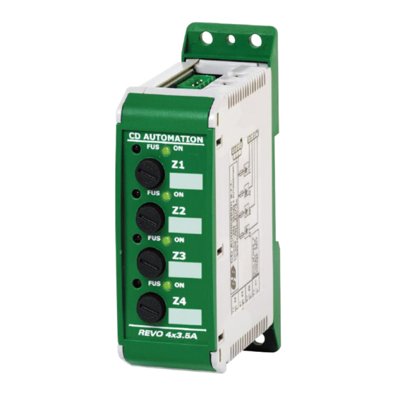
- Page 1 USER’S MANUAL Rev. 07/2019 Solid-State Relay 4x3,5A - 3x4,5A - 2x7A M-RSX CD Automation S.r.l. Via Picasso, 34/36 - 20025 Legnano (MI)- Italy Tel. +39 0331 577479 - Fax +39 0331 579479 E-mail: info@cdautomation.com - Web: www.cdautomation.com...
-
Page 3: Declaration Of Conformity
Declaration of conformity Declaration of conformity - Dichiarazione di Conformità PRODUCT MANUFACTURER / PRODUTTORE: CD Automation S.R.L. Controllers, Drives & Automation Via Picasso, 34/36 - 20025 Legnano (MI)- Italy P.I. 08925720156 -Tel. +39 0331 577479 - Fax +39 0331 579479 E-mail: info@cdautomation.com - Web: www.cdautomation.com... -
Page 4: Important Warnings For Safety
User’s manual REVO SX Important warnings for safety This chapter contains important information for the safety. The not observance of these instructions may result in serious personal injury or death and can cause serious damages to the Thyristor unit and to the components system included. - Page 5 User’s manual REVO SX WARNING! All service including inspection, installation, wiring, maintenance, troubleshooting, fuse or other user serviceable component replacement must be performed only by properly qualified personnel. Service personnel must read this manual before proceeding with work. While service is being performed unqualified personnel should not work on the unit or be allowed in the immediate vicinity.
- Page 6 User’s manual REVO SX AVERTISSEMENT! Au moment de relever des mesures de tension ou de courant en direct, utiliser un équipement de protection individuelle approprié pour les tensions et les potentiels d’arc électrique concernés. WARNING! Verify the voltage and current ratings of the power controller are correct for the application. AVERTISSEMENT! Vérifier que les valeurs de tension et de courant du régulateur de puissance sont correctes pour l’application.
-
Page 7: Maintenance
User’s manual REVO SX Maintenance In order to have a corrected cooling, the user must clean the heat-sink and the protective grill of the fans. The frequency of this servicing depends on environmental pollution. Also check periodically if the screw for the power cables and safety earth are tightened correctly (See Connection Diagram). -
Page 8: Table Of Contents
User’s manual REVO SX Summary Declaration of conformity ......3 Important warnings for safety ......4 Maintenance . -
Page 9: Basic Connections
User’s manual REVO SX Basic Connections Wiring with resistive load I= P V V = Nominal voltage of the load I = Nominal current of the load P = Nominal power of the load Order Code REVO SX NUMBER OF ZONES X CURRENT RATING INPUT description code... -
Page 10: Technical Specifications
User’s manual REVO SX Technical Specifications General features Cover and Socket material: PolymericV2 Mounting: DIN bar (thickness type 1mm Max) Utilization Category: AC-51 AC-55b IP Code: Method of Connecting: Single Phase load Delay switch ON/OFF time: 1/2 Period Max Input features Logic input SSR: 4 ÷... -
Page 11: Firing Type
User’s manual REVO SX Firing Type ZC firing mode is used with Logic Output from temperature controllers and the Thyristor operates like a contactor. The Cycle time is performed by temperature controller. ZC minimizes interferences because the Thyristor unit switches ON-OFF at zero voltage. Voltage Supply (V) Load Voltage (V) SSR from controller... -
Page 12: Installation
User’s manual REVO SX Installation Before install thyristor unit examine damages or deficiencies. If any is found, notify the ≥5 cm carrier immediately. Check that the product features shown on unit cover corresponds to that ordered. The thyristor unit should be always mounted in vertical ≥2 cm position to improve air cooling on heat-sink. -
Page 13: Wiring Instructions
User’s manual REVO SX Wiring instructions The Thyristor unit could be susceptible to interferences lost by near equipments or by the power supply, for this reason in accord to the fundamental practices rules is opportune take some precautions: • The coil contactor, the relays and other inductive loads must be equipped with opportune RC filter. •... -
Page 14: Terminals 480V
User’s manual REVO SX Terminals 480V Terminal Description Z4 (+) Control Input (SSR/0-10Vdc/4-20mA) Z4 (-) Control Input (SSR/0-10Vdc/4-20mA) Z3 (+) Control Input (SSR/0-10Vdc/4-20mA) Z3 (-) Control Input (SSR/0-10Vdc/4-20mA) Z2 (+) Control Input (SSR/0-10Vdc/4-20mA) Z2 (-) Control Input (SSR/0-10Vdc/4-20mA) Z1 (+) Control Input (SSR/0-10Vdc/4-20mA) Z1 (-) Control Input (SSR/0-10Vdc/4-20mA) Not connected Not connected... -
Page 15: Diagram Of Control Connection 4X3,5A - 230V
User’s manual REVO SX Diagram of control connection 4x3,5A - 230V LOAD Input: SSR Z1 SSR Z2 SSR Z3 SSR Z4 Note: • A suitable device must ensure that the unit can be electrically isolated from the supply, this allows the qualified people to work in safety (*). -
Page 16: Diagram Of Control Connection 4X3,5A - 480V
User’s manual REVO SX Diagram of control connection 4x3,5A - 480V LOAD 12 11 10 9 Input: AUX 12-24 AC/DC SSR Z1 (only with 480V) SSR Z2 Not connected SSR Z3 SSR Z4 Note: • A suitable device must ensure that the unit can be electrically isolated from the supply, this allows the qualified people to work in safety (*). -
Page 17: Diagram Of Control Connection 3X4,5A - 230V
User’s manual REVO SX Diagram of control connection 3x4,5A - 230V LOAD Input: SSR Z1 SSR Z2 Not connected SSR Z3 Note: • A suitable device must ensure that the unit can be electrically isolated from the supply, this allows the qualified people to work in safety (*). -
Page 18: Diagram Of Control Connection 3X4,5A - 480V
User’s manual REVO SX Diagram of control connection 3x4,5A - 480V LOAD 12 11 10 9 Input: AUX 12-24 AC/DC SSR Z1 (only with 480V) SSR Z2 Not connected SSR Z3 Note: • A suitable device must ensure that the unit can be electrically isolated from the supply, this allows the qualified people to work in safety (*). -
Page 19: Diagram Of Control Connection 2X7A - 230V
User’s manual REVO SX Diagram of control connection 2x7A - 230V LOAD Input: SSR Z1 Not connected SSR Z3 Note: • A suitable device must ensure that the unit can be electrically isolated from the supply, this allows the qualified people to work in safety (*). •... -
Page 20: Diagram Of Control Connection 2X7A - 480V
User’s manual REVO SX Diagram of control connection 2x7A - 480V LOAD 12 11 10 9 Input: AUX 12-24 AC/DC SSR Z1 (only with 480V) Not connected SSR Z3 Note: • A suitable device must ensure that the unit can be electrically isolated from the supply, this allows the qualified people to work in safety (*). -
Page 21: Led Status And Alarms
User’s manual REVO SX Led status and Alarms 230V 480V Fuse OK Fuse Fault GREEN Load is NOT powered Loas IS powered... -
Page 22: Internal Fuse
User’s manual REVO SX Internal Fuse The thyristor unit must be protected against short circuit by High speed fuses. The Fuses must have I²t 20% less than thyristor’s I²t. The warranty of thyristor is null if no proper fuses are used. Change the Fuses: Press, turn in counter-clockwise and release Extract the fuse... - Page 23 CD Automation S.r.l. Via Picasso, 34/36 - 20025 Legnano (MI)- Italy Tel. +39 0331 577479 - Fax +39 0331 579479 E-mail: info@cdautomation.com - Web: www.cdautomation.com...
Need help?
Do you have a question about the REVO SX Series and is the answer not in the manual?
Questions and answers