Table of Contents
Advertisement
Quick Links
Advertisement
Table of Contents

Related Manuals for CD Automation Revo S


Summary of Contents for CD Automation Revo S
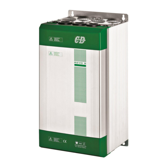
- Page 1 Revo USER’S MANUAL Rev. 6/2016 Solid State Relay from 280 to 700 A 00023 CD Automation S.r.l. Via Picasso 34/36 - 20025 – Legnano (MI) – ITALY Tel +39 0331 577479 – Fax +39 0331 579479 E-Mail: info@cdautomation.com - WEB:...
- Page 2 CD Automation srl REVO S User’s Manual...
-
Page 3: Table Of Contents
CD Automation srl REVO S User’s Manual 1 Important warning for safety ............................ 5 2 Basic Connections and sizing ............................. 6 3 Identification and Order Code ........................... 7 3.1 Identification of the unit 3.2 Order Code 4 Technical Specifications ............................9 4.1 General features:... - Page 4 CD Automation srl REVO S User’s Manual CD Automation s.r.l. Controllers, Drives & Automation Via Picasso, 34/36 - 20025 Legnano (MI)- Italia P.I. 08925720156 -Tel. (0331) 577479 - Fax (0331) 579479 Internet : www.cdautomation.com - E-MAIL: info@cdautomation.com Dichiarazione di Conformità...
-
Page 5: Important Warning For Safety
Emissions (Emissioni, Emission) All solid-state power controllers emit a certain amount of radio-frequency energy because of the fast switching of the power devices. The CD Automation’s Thyristor unit are in accord with the EMC norms, CE mark. In most installations, near by electronic systems will experience no difficulty with interference. If very sensitive electronic measuring equipment or low-frequency radio receivers are to be used near the unit, some special precautions may be required. -
Page 6: Basic Connections And Sizing
CD Automation srl REVO S User’s Manual 2 Basic Connections and sizing Star wiring with resistive load (control on two phases with REVO M-2PH) V = Nominal voltage of the load I = Nominal current of the load P = Nominal power of the load Delta wiring with resistive load (control on two phases with REVO M-2PH) ... -
Page 7: Identification And Order Code
CD Automation srl REVO S User’s Manual 3 Identification and Order Code 3.1 Identification of the unit Caution: Before to install, make sure that the Thyristor unit have not damages. If the product has a fault, please contact the dealer from which you purchased the product. -
Page 8: Order Code
CD Automation srl REVO S User’s Manual 3.2 Order Code CD-Eng-REVO-S-2PH-280-700A-Solid-State-Relay... -
Page 9: Technical Specifications
CD Automation srl REVO S User’s Manual 4 Technical Specifications 4.1 General features: Cover and Socket material: PolymericV2 Utilization Category AC-51 AC-55b IP Code Method of Connecting Load in Delta, Load in Star (8 VA Max) 90:130V (8 VA Max) -
Page 10: Environmental Installation Conditions
CD Automation srl REVO S User’s Manual 5 Installation Before to install, make sure that the Thyristor unit have not damages. If the product has a fault, please contact the dealer from which you purchased the product. Verify that the product is the same thing as ordered. -
Page 11: Dimensions And Weight
CD Automation srl REVO S User’s Manual 5.3 Dimensions and Weight REVO-S 2PH REVO-S 2PH 280A (S10) 400A÷700A (S14) Size W(mm) H(mm) D(mm) Weight (kg) 280A (2xS10) 400A (SR15) 22,5 450A (SR15) 22,5 500A (SR15) 22,5 600A (SR15) 22,5 700A (SR15) -
Page 12: Fixing Holes
CD Automation srl REVO S User’s Manual 5.4 Fixing holes REVO-S 2PH REVO-S 2PH 280A (S10) 400A÷700A (S14) Size A(mm) B(mm) 280A (S10) 400A (S14) 450A (S14) 500A (S14) 600A (S14) 700A (S14) CD-Eng-REVO-S-2PH-280-700A-Solid-State-Relay... -
Page 13: Wiring Instructions
CD Automation srl REVO S User’s Manual 6 Wiring instructions The Thyristor unit could be susceptible to interferences lost by near equipments or by the power supply, for this reason in accord to the fundamental practices rules is opportune take some precautions: ... -
Page 14: Power Cable Dimensions (Suggested)
CD Automation srl REVO S User’s Manual 6.3 Power cable dimensions (suggested) Supply Load Current Cable Screw Cable Screw mm² mm² 280A (S10) 400A (S14) 2 x 95 2 x 3/0 2 x 95 2 x 3/0 450A (S14) Bus Bar... -
Page 15: Control Terminals Positions
CD Automation srl REVO S User’s Manual 6.5 Terminals Positions CD-Eng-REVO-S-2PH-280-700A-Solid-State-Relay... -
Page 16: Power Terminals
CD Automation srl REVO S User’s Manual REVO-S 2PH REVO-S 2PH 280A (S10) 400A÷700A (S14) 6.6 Power Terminals Warning: Before connecting or disconnecting the unit check that power and control cables are isolated from voltage sources. Terminal Description Line Input Phase 1... -
Page 17: Command Terminals For Ssr Input Only On S10 (280A)
CD Automation srl REVO S User’s Manual 6.7 Command Terminals for SSR Input only on S10 (280A) Warning: Before connecting or disconnecting the unit check that power and control cables are isolated from voltage sources. Standard Terminals Terminal Description Aux – Voltage Supply for elettronic boards (... -
Page 18: Schematic On S10 (280A)
CD Automation srl REVO S User’s Manual 6.9 Schematic on S10 (280A) Caution: this procedure must be performed only by qualified persons. NOTE: *1 The user installation must be protecting by electromagnetic circuit breaker or by fuse isolator. The semiconductor I2t should be 20% less than power controller I2t. -
Page 19: Connection Diagram For 3 Phases (Control On 2 Phases) On S10 280A
CD Automation srl REVO S User’s Manual Caution: this procedure must be performed only by qualified persons. 6.10 Connection Diagram for 3 phases (control on 2 phases) on S10 280A X = not connected *1 The user installation must be protecting by electromagnetic circuit breaker or by fuse isolator. -
Page 20: Commmand Terminals For Ssr Input Only On S14 (400-700A)
CD Automation srl REVO S User’s Manual 6.11 Commmand Terminals for SSR Input only on S14 (400-700A) Warning: Before connecting or disconnecting the unit check that power and control cables are isolated from voltage sources. Standard Terminals Terminal Description Not Connected... -
Page 21: Schematic On S14 (400-700A)
CD Automation srl REVO S User’s Manual 6.13 Schematic on S14 (400-700A) Caution: this procedure must be performed only by qualified persons. NOTE: *1 The user installation must be protecting by electromagnetic circuit breaker or by fuse isolator. The semiconductor I2t should be 20% less than power controller I2t. -
Page 22: Connection Diagram For 3 Phases (Control On 2 Phases) On S14 400-700A
CD Automation srl REVO S User’s Manual 6.14 Connection Diagram for 3 phases (control on 2 phases) on S14 400-700A X = not connected *1 The user installation must be protecting by electromagnetic circuit breaker or by fuse isolator. The semiconductor I2t should be 20% less than power controller I2t. -
Page 23: Led Status And Alarms
CD Automation srl REVO S User’s Manual 7 Led status and Alarms DESCRIPTION STATUS LED OFF Load OK H.B. LED ON (Yellow) Load Fault (only with HB option) S.C. LED ON (Red) SCR short circuit (only with HB option) LED OFF... -
Page 24: Supply The Electronic Board
User’s Manual 9 Supply the Electronic Board The REVO S thyristor unit, to work, requires a voltage supply for the electronic boards. The Max consumption is 10VA. The voltage supply for the electronic boards is configured in line with customer requirements that are defined in the Order Code. -
Page 25: Input Setting
CD Automation srl REVO S User’s Manual 10 Input setting The input type is already configured in line with customer requirements that are defined in the Order Code. However, verify that the jumper are set as below represented: Warning: Before operate, be sure that power and control cables are isolated from voltage... -
Page 26: Input Calibration Procedure
CD Automation srl REVO S User’s Manual 10.1 Input calibration procedure Warning: this procedure can be done just by specialized personnel This procedure is needed only if you change the input type Start TUNE Auxiliary power supply Mantain Key CAL pushed 2sec. -
Page 27: Firing Type
CD Automation srl REVO S User’s Manual 11 Firing type Choose a correct firing type allows to optimize the thyristor unit for the installed load. The firing type has already configured in line with customer requirements,Zero Crossing for SSR input and Burst firing for Analog Input. -
Page 28: Burst Firing Settings
CD Automation srl REVO S User’s Manual 11.3 Burst Firing settings The Burst Firing cycles is already configured in line with customer requirements that are defined in the Order Code. However, if you wish to change the Burst Firing cycles (es. from 4 to 8) set the jumpers as... -
Page 29: Internal Fuse
CD Automation srl REVO S User’s Manual 12 Internal Fuse The thyristor unit have internal fuse extrarapid at low I²t for the thyristor protection of against the short-circuits. The Fuses must have I²t 20% less than thyristor's I²t. The warranty of thyristor is null if no proper fuses are used. -
Page 30: Maintenance
Warranty does not include products with serial numbers deleted. The faulty product should be shipped to CD Automation at customer’s cost and our Service will evaluate if product is under warranty terms. Substituted parts remain of CD Automation property. - Page 31 CD Automation srl REVO S User’s Manual CD-Eng-REVO-S-2PH-280-700A-Solid-State-Relay...
Need help?
Do you have a question about the Revo S and is the answer not in the manual?
Questions and answers