Table of Contents
Advertisement
Pos : 2 /D okumentati on allgemein/Ei nband/Ei nband H andbuch - Dec kbl att ohne Variantenfel d (Standar d) @ 9\mod_1285229289866_0.doc x @ 64941 @ @ 1
Manual
WAGO-I/O-SYSTEM 750
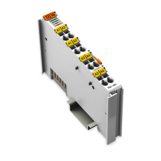
2/4 AI RTD configurable
750-464
2-/4-Channel Analog Input Module for RTDs
Version 1.0.1
Pos : 3 /Alle Serien (Allgemeine M odul e)/Hinweise z ur Dokumentation/Impres sum für Standardhandbüc her - allg. Angaben, Ansc hriften, Tel efonnummer n und E-Mail-Adres sen @ 3\mod_1219151118203_21.doc x @ 21060 @ @ 1
Advertisement
Chapters
Table of Contents

Related Manuals for WAGO 750-464


Summary of Contents for WAGO 750-464
- Page 1 Pos : 2 /D okumentati on allgemein/Ei nband/Ei nband H andbuch - Dec kbl att ohne Variantenfel d (Standar d) @ 9\mod_1285229289866_0.doc x @ 64941 @ @ 1 Manual WAGO-I/O-SYSTEM 750 2/4 AI RTD configurable 750-464 2-/4-Channel Analog Input Module for RTDs Version 1.0.1...
- Page 2 WAGO-I/O-SYSTEM 750 750-464 2/4 AI RTD configurable © 2013 by WAGO Kontakttechnik GmbH & Co. KG All rights reserved. WAGO Kontakttechnik GmbH & Co. KG Hansastraße 27 D-32423 Minden Phone: +49 (0) 571/8 87 – 0 Fax: +49 (0) 571/8 87 – 1 69 E-Mail: info@wago.com...
-
Page 3: Table Of Contents
Connect Devices ..................31 ® Connecting a Conductor to the CAGE CLAMP ........31 Connection Examples ................32 5.2.1 750-464 (RTD) Version, 4-Channel Operation ........32 5.2.1.1 4 x 2-Wire ..................32 5.2.1.2 Special Features in 4-Channel Operation ........32 5.2.1.2.1 Open Input Wiring .............. - Page 4 Toolbar on the Configuration Dialog ..........53 6.3.3 2/4-Channel Input Module for Resistence Sensors 750-464 (navigation area) ................. 54 6.3.3.1 2/4-Channel Analog Input Module for Resistance Sensors 750-464 (general) ..................55 6.3.3.2 2/4-Channel Analog Input Module for Resistance Sensors 750-464 (channels) ..................56 6.3.3.3...
- Page 5 WAGO-I/O-SYSTEM 750 Table of Contents 750-464 2/4 AI RTD configurable Process Data of the Standard Version 750-464 (RTD, configurable) ..73 7.3.1 Pt100 (acc. IEC 751) ................73 7.3.2 Pt200 (acc. IEC 751) ................74 7.3.3 Pt500 (acc. IEC 751) ................75 7.3.4...
-
Page 6: 750-464 2/4 Ai Rtd Configurable
Table of Contents WAGO-I/O-SYSTEM 750 750-464 2/4 AI RTD configurable List of Figures ....................115 List of Tables ...................... 116 === Ende der Liste für T extmar ke Verzeic hnis_vor ne === Manual Version 1.0.1... -
Page 7: Notes About This Documentation
Pos : 11 /Serie 750 ( WAGO-I/O-SYST EM)/Hi nweis e z ur D okumentati on/Variantenlisten/Variantenliste - 750-464 - Standar dversi on und Variante /020-000 (4 AI NTC fr ei konfigurierbar) @ 12\mod_1334642765393_21.doc x @ 93584 @ @ 1... -
Page 8: Symbols
WAGO-I/O-SYSTEM 750 750-464 2/4 AI RTD configurable Pos : 13.3 /All e Seri en ( Allgemei ne Module)/Ü bers chriften für alle Serien/Hinweis z ur D okumentati on/Symbole - Ü berschrift 2 @ 13\mod_1351068042408_21.doc x @ 105270 @ 2 @ 1 Symbols Pos : 13.4.1 /All e Serien ( Allgemei ne Module)/Wic htige Erläuterungen/Sicherheits- und sons tige Hinweis e/Gefahr/Gefahr: _War nung vor Personenschäden allgemei n_ - Erl äuter ung @ 13\mod_1343309450020_21.doc x @ 101029 @ @ 1... - Page 9 WAGO-I/O-SYSTEM 750 Notes about this Documentation 750-464 2/4 AI RTD configurable Additional Information: Refers to additional information which is not an integral part of this documentation (e.g., the Internet). Pos : 13.5 /Dokumentation allgemei n/Glieder ungs elemente/---Seitenwechs el--- @ 3\mod_1221108045078_0.doc x @ 21810 @ @ 1 Manual Version 1.0.1...
-
Page 10: Number Notation
Notes about this Documentation WAGO-I/O-SYSTEM 750 750-464 2/4 AI RTD configurable Pos : 13.6 /All e Seri en ( Allgemei ne Module)/Hi nweis e zur D okumentati on/Zahlens ysteme @ 3\mod_1221059454015_21.doc x @ 21711 @ 2 @ 1 Number Notation... -
Page 11: Important Notes
All changes to the coupler or controller should always be carried out by qualified personnel with sufficient skills in PLC programming. Pos : 16.5 /Serie 750 (WAGO-I/O-SYST EM)/Wic htige Erläuterungen/Bes timmungsgemäß e Verwendung 750- xxxx @ 3\mod_1224064151234_21.doc x @ 24070 @ 3 @ 1 2.1.3... -
Page 12: Technical Condition Of Specified Devices
The components to be supplied Ex Works, are equipped with hardware and software configurations, which meet the individual application requirements. WAGO Kontakttechnik GmbH & Co. KG will be exempted from any liability in case of changes in hardware or software as well as to non-compliant usage of components. -
Page 13: Safety Advice (Precautions)
Pos : 16.10.2 /Serie 750 ( WAGO-I/O- SYST EM)/Wic htig e Erl äuter ung en/Sic her hei ts- und s onstige Hi nweise/Gefahr/Gefahr: Ei nbau 0750- xxxx nur i n Gehäus en, Sc hränken oder el ektrisc hen Betriebsräumen! @ 6\mod_1260180556692_21.doc... - Page 14 Important Notes WAGO-I/O-SYSTEM 750 750-464 2/4 AI RTD configurable Do not use any contact spray! Do not use any contact spray. The spray may impair contact area functionality in connection with contamination. Pos : 16.11.5 /Alle Serien (Allgemeine M odul e)/Wichtige Erläuter ungen/Sic herheits- und s onstige Hinweise/Ac htung/Ac htung: Verpol ung ver mei den! @ 6\mod_1260184045744_21.doc x @ 46767 @ @ 1...
-
Page 15: Device Description
Pos : 19.10 /Serie 750 ( WAGO-I/O-SYST EM)/Wichtig e Erl äuter ung en/Sic her hei ts- und s onstige Hinweise/Hinweis/Hi nweis : Potenti aleinspeis eklemme für Erde eins etz en! @ 3\mod_1226499037468_21.doc x @ 25023 @ @ 1 Use potential feed module for Ground (earth)! The I/O module has no power contacts for PE intake and transfer. -
Page 16: View
750-464 2/4 AI RTD configurable Pos : 19.13 /Serie 750 ( WAGO-I/O-SYST EM)/Gerätebeschr eibung/Ei nleitung/Einsatzbereic h/Einsatzbereic h 750- xxxx alle Koppler/C ontroll er ohne Ec onomy- Koppler @ 3\mod_1232541867468_21.doc x @ 26525 @ @ 1 The I/O module 750-464 can be used with all fieldbus couplers/controllers of the WAGO-I/O-SYSTEM 750 (except for the economy types 750-320, -323, -324 and -327). -
Page 17: Connectors
Pos : 25.3 /Serie 750 (WAGO-I/O-SYST EM)/Wic htige Erläuterungen/Sicherheits- und sonstig e Hinweis e/Achtung/Achtung: ESD - Auf g ute Erdung der U mgebung ac hten! @ 7\mod_1266318538667_21.doc x @ 50708 @ @ 1 Ensure that the environment is well grounded! The modules are equipped with electronic components that may be destroyed by electrostatic discharge. -
Page 18: Power Jumper Contacts/Field Supply
Power Jumper Contacts/Field Supply Pos : 28.1 /Serie 750 (WAGO-I/O-SYST EM)/Wic htige Erläuterungen/Sicherheits- und sonstig e Hinweis e/Vorsic ht/Vorsicht: Verl etz ungsgefahr durc h s charfkantige M ess er kontakte! @ 6\mod_1256193279401_21.doc x @ 43414 @ @ 1 Risk of injury due to sharp-edged male contacts! The male contacts are sharp-edged. -
Page 19: Cage Clamp
Device Description 750-464 2/4 AI RTD configurable Pos : 30 /Serie 750 ( WAGO-I/O-SYST EM)/Ger ätebesc hrei bung/Ansc hl üss e/CAGE CLAMP- Anschl üss e - Ü berschrift 3 @ 6\mod_1256296337770_21.doc x @ 43674 @ 3 @ 1 ® 3.2.3... -
Page 20: Connections 2-Channel, 2-Wire
Figure 6: Connections contacts Pos : 32 /Serie 750 ( WAGO-I/O-SYST EM)/Wic htige Erläuterungen/Sicherheits- und sonstig e Hinweis e/Hi nweis /Hinweis: Geschir mte Signalleitung en ver wenden! @ 7\mod_1265723251019_21.doc x @ 50140 @ @ 1 Use shielded signal lines! Only use shielded signal lines for analog signals and I/O modules which are equipped with shield clamps. -
Page 21: Display Elements
Pos : 34 /All e Seri en (Allgemei ne Module)/Ü berschriften für alle Serien/Gerätebesc hreibung/Anz eigeel emente - Übersc hrift 2 @ 4\mod_1240984390875_21.doc x @ 31964 @ 2 @ 1 Display Elements Pos : 35 /Serie 750 ( WAGO-I/O-SYST EM)/Ger ätebesc hrei bung/Anz eigeelemente/Anal ogei ngangs klemmen/Anz eigeel emente 750- 0464 @ 6\mod_1264150788609_21.doc x @ 48344 @ @ 1 Table 9: Display elements... -
Page 22: Operating Elements
Pos : 38 /All e Seri en (Allgemei ne Module)/Ü berschriften für alle Serien/Gerätebesc hreibung/Sc hematisches Sc haltbil d - Ü bersc hrift 2 @ 4\mod_1240984441312_21.doc x @ 31967 @ 2 @ 1 Schematic Diagram Pos : 39 /Serie 750 ( WAGO-I/O-SYST EM)/Ger ätebesc hrei bung/Schematisc he Sc haltbil der/Anal ogeing angs kl emmen/Sc hematisc hes Sc haltbild 750-0464 @ 4\mod_1243491684000_21.doc x @ 34050 @ @ 1 Figure 8: Schematic diagram Pos : 40 /D okumentation allgemei n/Glieder ungs elemente/---Seitenwechs el--- @ 3\mod_1221108045078_0.doc x @ 21810 @ @ 1... -
Page 23: Technical Data
Pos : 41 /All e Seri en (Allgemei ne Module)/Ü berschriften für alle Serien/Gerätebesc hreibung/Technisc he Daten - Ü berschrift 2 @ 3\mod_1232967587687_21.doc x @ 26924 @ 2 @ 1 Technical Data Pos : 42 /Serie 750 ( WAGO-I/O-SYST EM)/Ger ätebesc hrei bung/T echnisc he Daten/Anal ogeing angs kl emmen/T ec hnis che D aten 750-0464 @ 5\mod_1245336534734_21.doc x @ 35646 @ 33333 @ 1 3.6.1... -
Page 24: Inputs (Rtd-Variant 750-464)
Device Description WAGO-I/O-SYSTEM 750 750-464 2/4 AI RTD configurable 3.6.4 Inputs (RTD-variant 750-464) Table 13: Technical data inputs (RTD-variant 750-464) Number of inputs 2 or 4 (parametrizable) Sensor types Pt100 (IEC 751, default), Ni100 (DIN 43760), Pt1000 (IEC 751), Pt500 (IEC 751),... -
Page 25: Approvals
Pos : 46 /Serie 750 ( WAGO-I/O-SYST EM)/Ger ätebesc hrei bung/Z ulass ungen/Allgemei n/Z ulass ungen Bus kl emme 750- xxxx Allgemein, Standardversi on und all e Vari anten - Einl eitung @ 3\mod_1233911570312_21.doc x @ 27390 @ @ 1... - Page 26 Device Description WAGO-I/O-SYSTEM 750 750-464 2/4 AI RTD configurable BV (Bureau Veritas) Pos : 54 /All e Seri en (Allgemei ne Module)/Z ulassungen/Sc hiffsz ul ass ungen/DN V (D et N ors ke Veritas) Cl ass B @ 3\mod_1224492540562_0.doc x @ 24224 @ @ 1...
-
Page 27: Standards And Guidelines
Pos : 62 /Serie 750 ( WAGO-I/O-SYST EM)/Ger ätebesc hrei bung/N ormen und Ric htlini en/EM V-Nor men Bus kl emme 750- xxxx, Standardversi on und all e Varianten - Einl eitung @ 6\mod_1263981980650_21.doc x @ 48120 @ @ 1... -
Page 28: Mounting
Pos : 69.2 /Serie 750 (WAGO-I/O-SYST EM)/Wic htige Erläuterungen/Sicherheits- und sonstig e Hinweis e/Vorsic ht/Vorsicht: Verl etz ungsgefahr durc h s charfkantige M ess er kontakte! @ 6\mod_1256193279401_21.doc x @ 43414 @ @ 1 Risk of injury due to sharp-edged male contacts! The male contacts are sharp-edged. -
Page 29: Inserting And Removing Devices
Inserting and Removing Devices Pos : 69.8 /Serie 750 (WAGO-I/O-SYST EM)/Wic htige Erläuterungen/Sicherheits- und sonstig e Hinweis e/Gefahr/Gefahr : Vorsic ht bei der U nterbr echung von F E! @ 6\mod_1256193919214_21.doc x @ 43423 @ @ 1 Use caution when interrupting the PE! Make sure that people or equipment are not placed at risk when removing an I/O module and the associated PE interruption. -
Page 30: Figure 11: Removing The I/O Module
Mounting WAGO-I/O-SYSTEM 750 750-464 2/4 AI RTD configurable Figure 11: Removing the I/O module Electrical connections for data or power contacts are disconnected when removing the I/O module. Pos : 70 /D okumentation allgemei n/Glieder ungs elemente/---Seitenwechs el--- @ 3\mod_1221108045078_0.doc x @ 21810 @ @ 1 Manual Version 1.0.1... -
Page 31: Connect Devices
Pos : 71 /All e Seri en (Allgemei ne Module)/Ü berschriften für alle Serien/Ansc hließ en/Ger äte ansc hließen - Ü bers chrift 1 @ 3\mod_1234172889468_21.doc x @ 27460 @ 1 @ 1 Connect Devices Pos : 72 /Serie 750 ( WAGO-I/O-SYST EM)/Ans chli eßen/Leiter an C AGE C LAM P ans chli eßen - Ü berschrift 2 und T ext @ 3\mod_1225448660171_21.doc x @ 24928 @ 2 @ 1 ®... -
Page 32: Connection Examples
Pos : 74 /All e Seri en (Allgemei ne Module)/Ü berschriften für alle Serien/Ansc hließ en/Ans chl uss beis piel e - Ü berschrift 2 @ 4\mod_1240996036328_21.doc x @ 32010 @ 2 @ 1 Connection Examples Pos : 75 /Serie 750 ( WAGO-I/O-SYST EM)/Wic htige Erläuterungen/Sicherheits- und sonstig e Hinweis e/Hi nweis /Hinweis: Geschir mte Signalleitung en ver wenden! @ 7\mod_1265723251019_21.doc x @ 50140 @ @ 1 Use shielded signal lines! Only use shielded signal lines for analog signals and I/O modules which are equipped with shield clamps. -
Page 33: 5.2.1.2.2 Measuring Circuit Line Break Detection
(large in relation to the converted temperature change), then this can influence the other channel within the measuring circuit. 5.2.2 750-464 (RTD) Version, 2-Channel Operation 5.2.2.1 2 x 2-Wire Figure 14: Connection example, version 750-464 (RTD), 2-channel, 2 x 2-wire Manual Version 1.0.1... -
Page 34: X 3-Wire
750-464 2/4 AI RTD configurable 5.2.2.2 2 x 3-Wire Figure 15: Connection example, version 750-464 (RTD), 2-channel, 2 x 3-Wire 5.2.2.3 1 x 2-Wire + 1 x 3-Wire Due to the adjustability by channel, all combinations of 2-wire and 3-wire connections are possible. -
Page 35: 750-464/020-000 (Ntc) Version
5.2.3.1 4 x 2-Wire Important information for 4-channel operation Please note the special features in the following chapter Figure 16: Connection example, version 750-464/020-000 (NTC) 5.2.3.2 Special Features 5.2.3.2.1 Influencing a Measuring Circuit Channel through a Quick Change in Temperature As a rule, temperatures change relatively slowly. -
Page 36: Commissioning
Pos : 80 /Serie 750 ( WAGO-I/O-SYST EM)/In Betrieb nehmen/Parametrier en über Register kommuni kation/Par ametri eren über R egister kommuni kati on, Ergänz ungsmodul für Kanal 2, 3 und 4 @ 6\mod_1263294036858_21.doc x @ 47875 @ @ 1 Manual Version 1.0.1... - Page 37 Set the parameters for channel 4 via control byte C3, status byte S3 and data bytes D6 and D7. Pos : 81 /Serie 750 ( WAGO-I/O-SYST EM)/In Betrieb nehmen/Parametrier en über Register kommuni kation/R egister bel egung 750-464 @ 6\mod_1260784382021_21.doc x @ 47070 @ 3 @ 1 Manual...
-
Page 38: Register Assignment
Commissioning WAGO-I/O-SYSTEM 750 750-464 2/4 AI RTD configurable 6.1.1 Register Assignment Table 15: Register 32 Register Function Memory Access Default settings Mode setting EEPROM 0x0106 Bit 0: User scaling The user scaling is switched off. The user scaling is switched on. -
Page 39: Table 15: Register 32
Table 15: Register 32 Register Function Memory Access Default settings Mode setting EEPROM 0x0106 Bit 12 ... 15: Characteristic or sensor types of the 750-464 (RTD) version Pt100 (IEC 751) Ni100 (DIN 43760) Pt1000 (IEC 751) Pt500 (IEC 751) Pt200... -
Page 40: Table 18: Register 35
The number of measured values averaged is indicated in register 37 and can be configured via WAGO-I/O-CHECK. Possible values are 2 and 3 (possibly 4). Mean value filtering is switched off by default (i.e. bit 7 = 0). -
Page 41: Control And Status Bytes For Register Communication
* Default settings Pos : 82 /Serie 750 ( WAGO-I/O-SYST EM)/In Betrieb nehmen/Parametrier en über Register kommuni kation/C ontrol- und Statusbyte bei R egister kommuni kati on, Basis modul für Kanal 1 @ 6\mod_1263295194171_21.doc x @ 47885 @ 3 @ 1 6.1.2... -
Page 42: Table 25: Status Byte S0 For Register Communication
Register communication, mirrored from control byte C0 Pos : 83 /Serie 750 ( WAGO-I/O-SYST EM)/In Betrieb nehmen/Parametrier en über Register kommuni kation/C ontrol- und Statusbyte bei R egister kommuni kati on, Ergänz ungsmodul für Kanal 2 @ 6\mod_1263295956983_21.doc x @ 47888 @ @ 1... -
Page 43: Table 31: Status Byte S3 For Register Communication
WAGO-I/O-SYSTEM 750 Commissioning 750-464 2/4 AI RTD configurable Table 31: Status Byte S3 for Register Communication Bit 7 Bit 6 Bit 5 Bit 4 Bit 3 Bit 2 Bit 1 Bit 0 Reg_Com Register number Register number Register number of the selected function (cf. „Register Assignment“ section),... -
Page 44: Setting Parameters Via Parameter Channels
WAGO-I/O-SYSTEM 750 750-464 2/4 AI RTD configurable Pos : 87 /Serie 750 ( WAGO-I/O-SYST EM)/In Betrieb nehmen/Parametrier en über Parameter kanal/Parametri eren über Parameter kanal Bes chr eibung 750- xxxx @ 6\mod_1260443515796_21.doc x @ 46980 @ 2334434 @ 1 sneaker Setting Parameters via Parameter Channels 6.2.1... -
Page 45: Communication Control (Register 57)
WAGO-I/O-SYSTEM 750 Commissioning 750-464 2/4 AI RTD configurable 6.2.2.2 Communication Control (Register 57) Parameter channel control and diagnostics are done via register 57. Table 33: Communication Control (Register 57) Request parameter Response parameter Request TGL_ PRM_ MORE parameter _PRM Response... - Page 46 Commissioning WAGO-I/O-SYSTEM 750 750-464 2/4 AI RTD configurable Table 34: Communication Control Parameters Parameter Value range Meaning TIMEOUT FALSE The transmission of the parameters has been completed within the stipulated time (parameter address 0). TRUE The maximum time for the transmission of the parameters between I/O module and application was exceeded.
-
Page 47: Parameter Sets
The I/O module is reset to the default setting. Pos : 88 /Serie 750 ( WAGO-I/O-SYST EM)/In Betrieb nehmen/Parametrier en über Parameter kanal/Parameter kanaladres sen 750-464 @ 6\mod_1263292139765_21.doc x @ 47866 @ 4 @ 1 6.2.3.2 I/O Module-Specific Parameter Data... -
Page 48: Table 36: Parameter Channel Address 0
Commissioning WAGO-I/O-SYSTEM 750 750-464 2/4 AI RTD configurable Table 36: Parameter channel address 0 Parameter channel Register Memory Access Default settings address 32 (proportionate) EEPROM 0x0000 Bit 0: 2/4-channel switching 4-channel operation is switched on. 2-channel operation is switched on. -
Page 49: Parameter Transmission Process
Channel 2 Channel 3 Channel 4 Pos : 89 /Serie 750 ( WAGO-I/O-SYST EM)/In Betrieb nehmen/Parametrier en über Parameter kanal/Parametri eren über Parameter kanal Abl auf 750- xxxx @ 7\mod_1265364872660_21.doc x @ 49850 @ 3444 @ 1 6.2.4 Parameter transmission process Parameter data are exchanged between application and bus modules by means of the Request-Response process. -
Page 50: Table 41: Restoring Factory Settings (Request)
Commissioning WAGO-I/O-SYSTEM 750 750-464 2/4 AI RTD configurable Table 41: Restoring factory settings (Request) Parameter Value Meaning TGL_MS != TGL_SM Initiate order PRM_RW = TRUE Write access A0 ... A7 Address of factory settings Response (I/O module) Table 42: Restoring factory settings (Response) -
Page 51: Reading/Writing Parameters (I/O Module-Specific)
WAGO-I/O-SYSTEM 750 Commissioning 750-464 2/4 AI RTD configurable 6.2.4.3 Reading/writing parameters (I/O module-specific) Request (Application) Table 43: Reading/writing parameters (Request) Parameter Value Meaning TGL_MS != TGL_SM Initiate order PRM_RW = FALSE Read access = TRUE Write access MORE_PRM = FALSE... -
Page 52: Parameterization With Wago-I/O-Check
Pos : 92.1 /Serie 759 (WAGO-Softwar e)/WAGO-I/O-CHEC K/750- 0464 2- /4- Kanal- Analog eingangs klemme für Wi ders tandssens oren/2/4-Kanal-Analogei ngangs klemme für Widerstands sens oren 750-464 (Parametrier dial og Allgemein) @ 6\mod_1263886720210_21.doc x @ 48043 @ 3 @ 1... -
Page 53: Toolbar On The Configuration Dialog
WAGO-I/O-SYSTEM 750 Commissioning 750-464 2/4 AI RTD configurable Pos : 92.3 /Serie 759 (WAGO-Softwar e)/WAGO-I/O-CHEC K/Allgemei n/Symbollei ste i m Parametri erdi alog mit D efault @ 6\mod_1264067855937_21.doc x @ 48258 @ 3 @ 1 6.3.2 Toolbar on the Configuration Dialog... -
Page 54: 2/4-Channel Input Module For Resistence Sensors
750-464 2/4 AI RTD configurable Pos : 92.5 /Serie 759 (WAGO-Softwar e)/WAGO-I/O-CHEC K/750- 0464 2- /4- Kanal- Analog eingangs klemme für Wi ders tandssens oren/2/4-Kanal-Analogei ngangs klemme für Widerstands sens oren 750-464 (Navig ation) @ 6\mod_1264061976070_21.doc x @ 48213 @ 3 @ 1 6.3.3... -
Page 55: 2/4-Channel Analog Input Module For Resistance Sensors
750-464 2/4 AI RTD configurable Pos : 92.7 /Serie 759 (WAGO-Softwar e)/WAGO-I/O-CHEC K/750- 0464 2- /4- Kanal- Analog eingangs klemme für Wi ders tandssens oren/2/4-Kanal-Analogei ngangs klemme für Widerstands sens oren 750-464 (Allgemein) @ 6\mod_1264071210328_21.doc x @ 48261 @ 4 @ 1 6.3.3.1... -
Page 56: 2/4-Channel Analog Input Module For Resistance Sensors
750-464 2/4 AI RTD configurable Pos : 92.9 /Serie 759 (WAGO-Softwar e)/WAGO-I/O-CHEC K/750- 0464 2- /4- Kanal- Analog eingangs klemme für Wi ders tandssens oren/2/4-Kanal-Analogei ngangs klemme für Widerstands sens oren 750-464 (Kanäl e) @ 6\mod_1263986474202_21.doc x @ 48117 @ 4 @ 1 6.3.3.2... -
Page 57: Table 48: "Channel" Parameters
NTC-Thermokon 10 kΩ Connection type 2-wire 2-wire connection technology 3-wire 3-wire connection technology (not for 750-464 in operating mode "4- channel" not for 750-464/000-020) Watchdog Timer The Watchdog timer is not active. The green LEDs illuminate continuously. The Watchdog timer is active. If no... - Page 58 Commissioning WAGO-I/O-SYSTEM 750 750-464 2/4 AI RTD configurable Table 48: "Channel" parameters Selection box Possible settings SIEMENS Format Off* No display of status indicators Display of status indicators in the bottom three bits: Bit 0: Overflow. Set for Overrange/Underrange (if "Overflow Limit"...
- Page 59 WAGO-I/O-SYSTEM 750 Commissioning 750-464 2/4 AI RTD configurable Table 48: "Channel" parameters Selection box Possible settings Important Note! The setting has no impact on the process data representation. The process value is always saturated on the respective resistance limits of the sensor type set.
-
Page 60: (Calibration)
750-464 2/4 AI RTD configurable Pos : 92.11 /Serie 759 ( WAGO-Software)/WAGO-I/O-CHEC K/750-0464 2-/4-Kanal-Analogei ngangs klemme für Widerstandss ens oren/2/4-Kanal-Anal ogeing angs kl emme für Widerstandss ensor en 750- 464 ( Kali brierung) @ 6\mod_1263986674780_21.doc x @ 48153 @ 4 @ 1 2/4 Analogei ngangs klemme Analog 750- 464 ( Skali erung) 6.3.3.3... - Page 61 WAGO-I/O-SYSTEM 750 Commissioning 750-464 2/4 AI RTD configurable Calibration independent of sensor type! Any sensor type selected can be calibrated independently! Use resistance decade boxes for calibration! For best possible calibration of the module, use resistors or resistance decade boxes that are a accurate as possible, i.e. exhibit low tolerance. Otherwise, the measuring accuracy specified in the data sheet may not be achieved! Pos : 92.12 /D okumentati on allgemei n/Gli ederungsel emente/---Seitenwec hs el--- @ 3\mod_1221108045078_0.doc x @ 21810 @ @ 1...
-
Page 62: (Scaling)
750-464 2/4 AI RTD configurable Pos : 92.13 /Serie 759 ( WAGO-Software)/WAGO-I/O-CHEC K/750-0464 2-/4-Kanal-Analogei ngangs klemme für Widerstandss ens oren/2/4-Kanal-Anal ogeing angs kl emme für Widerstandss ensor en 750- 464 ( Skalierung) @ 6\mod_1263986590358_21.doc x @ 48150 @ 4 @ 1 6.3.3.4... - Page 63 WAGO-I/O-SYSTEM 750 Commissioning 750-464 2/4 AI RTD configurable m = Gain [1/256 per digit, data type: unsigned integer], x = Resistance or temperature value b = Offset If connection type "2-wire" is set in the 2-wire offset field for a connected resistance/temperature sensor, the line resistance of the sensor has a direct impact on the measurement results and can this distort it.
-
Page 64: Process Image
Process Image Pos : 95 /Serie 750 ( WAGO-I/O-SYST EM)/Proz ess abbild Kl emmenbus /Hinweis: Prozes sabbildmapping abhängig von FBK/PFC, mit Status-/C ontroll byte @ 4\mod_1242621308640_21.doc x @ 33290 @ @ 1 Mapping of process data in the process image of fieldbus systems The representation of the process data of some I/O modules or their variations in the process image depends on the fieldbus coupler/controller used. -
Page 65: Control/Status Bytes
WAGO-I/O-SYSTEM 750 Process Image 750-464 2/4 AI RTD configurable Control/Status Bytes Table 51: Control Byte C0 Bit 7 Bit 6 Bit 5 Bit 4 Bit 3 Bit 2 Bit 1 Bit 0 RegCom RegCom Register Communication Register communication is switched off (normal mode) Register communication is switched on (configuration, see section "Setting Parameters via Register Communication") -
Page 66: Table 52: Status Byte S0
Process Image WAGO-I/O-SYSTEM 750 750-464 2/4 AI RTD configurable Table 52: Status byte S0 User Underrange User underrange The process value is greater than specified for the underrange (see section “Feature Register”). The process value is less than specified for the underrange. The format of the number notation (see section "Feature Register") is taken into... - Page 67 WAGO-I/O-SYSTEM 750 Process Image 750-464 2/4 AI RTD configurable Table 53: Control Byte C1 Bit 7 Bit 6 Bit 5 Bit 4 Bit 3 Bit 2 Bit 1 Bit 0 RegCom RegCom Register Communication Register communication is switched off (normal mode) Register communication is switched on (configuration, see section "Setting Parameters via Register Communication")
-
Page 68: Table 54: Status Byte S1
Process Image WAGO-I/O-SYSTEM 750 750-464 2/4 AI RTD configurable Table 54: Status byte S1 User Underrange User underrange The process value is greater than specified for the underrange (see section “Feature Register”). The process value is less than specified for the underrange. The format of the number notation (see section "Feature Register") is taken into... - Page 69 WAGO-I/O-SYSTEM 750 Process Image 750-464 2/4 AI RTD configurable Table 55: Control Byte C2 Bit 7 Bit 6 Bit 5 Bit 4 Bit 3 Bit 2 Bit 1 Bit 0 RegCom RegCom Register Communication Register communication is switched off (normal mode) Register communication is switched on (configuration, see section "Setting Parameters via Register Communication")
-
Page 70: Table 56: Status Byte S2
Process Image WAGO-I/O-SYSTEM 750 750-464 2/4 AI RTD configurable Table 56: Status byte S2 User Underrange User underrange The process value is greater than specified for the underrange (see section “Feature Register”). The process value is less than specified for the underrange. The format of the number notation (see section "Feature Register") is taken into... - Page 71 WAGO-I/O-SYSTEM 750 Process Image 750-464 2/4 AI RTD configurable Table 57: Control Byte C3 Bit 7 Bit 6 Bit 5 Bit 4 Bit 3 Bit 2 Bit 1 Bit 0 RegCom RegCom Register Communication Register communication is switched off (normal mode) Register communication is switched on (configuration, see section "Feature Register")
-
Page 72: Table 58: Status Byte S3
Process Image WAGO-I/O-SYSTEM 750 750-464 2/4 AI RTD configurable Table 58: Status byte S3 User Underrange User underrange The process value is greater than specified for the underrange (see section “Feature Register”). The process value is less than specified for the underrange. The format of the number notation (see section "Feature Register") is taken into... -
Page 73: Process Data Of The Standard Version 750-464 (Rtd, Configurable)
100 °C to the numeric value 0x03E8 (dec. 1000). The possible numeric range corresponds to the defined temperature range of -200 °C to +850 °C for Pt100 sensors (acc. IEC 751). Table 59: Process image for 750-464, Pt100 setting (acc. IEC 751) Status Numeric value... -
Page 74: Pt200 (Acc. Iec 751)
100 °C to the numeric value 0x03E8 (dec. 1000). The possible numeric range corresponds to the defined temperature range of -200 °C to +850 °C for Pt200 sensors (acc. IEC 751). Table 60: Process image for 750-464, Pt200 setting (acc. IEC 751) Status Numeric value... -
Page 75: Pt500 (Acc. Iec 751)
100 °C to the numeric value 0x03E8 (dec. 1000). The possible numeric range corresponds to the defined temperature range of -200 °C to +850 °C for Pt500 sensors (acc IEC 751). Table 61: Process image for 750-464, Pt500 setting (acc. IEC 751) Status Numeric value... -
Page 76: Pt1000 (Acc. Iec 751)
100 °C to the numeric value 0x03E8 (dec. 1000). The possible numeric range corresponds to the defined temperature range of -200 °C to +850 °C for Pt1000 sensors (acc. IEC 751). Table 62: Process image for 750-464, Pt1000 setting (acc. IEC 751) Status Numeric value... -
Page 77: Ni100 (Acc. Din 43760)
100 °C to the numeric value 0x03E8 (dec. 1000). The possible numeric range corresponds to the defined temperature range of -60 °C to +300 °C for Ni100 sensors (acc. DIN 43760). Table 63: Process image for 750-464, Ni100 setting (acc. DIN 43760) Status Numeric value... -
Page 78: Ni120 (Minco)
100 °C to the numeric value 0x03E8 (dec. 1000). The possible numeric range corresponds to the defined temperature range of -80 °C to +260 °C for Ni120 sensors (Minco). Table 64: Process image for 750-464, Ni120 setting (Minco) Status Numeric value... -
Page 79: Ni1000 (Acc. Din 43760)
100 °C to the numeric value 0x03E8 (dec. 1000). The possible numeric range corresponds to the defined temperature range of -60 °C to +300 °C for Ni1000 sensors (acc. DIN 43760). Table 65: Process image for 750-464, Ni1000 setting (acc. DIN 43760) Status Numeric value... -
Page 80: Ni1000 Tk5000
100 °C to the numeric value 0x03E8 (dec. 1000). The possible numeric range corresponds to the defined temperature range of -60 °C to +250 °C for type Ni1000 TK5000 sensors. Table 66: Process image for 750-464, type Ni1000 TK5000 sensor setting Status Numeric value... -
Page 81: Resistance Measurement 10 Ohm To 1.2 Kohm
The resistances values are displayed at a resolution of 1 digit per 0.1 Ω in one word (16-bit). The possible numeric range corresponds to the defined measurement range of 10 Ω to 1.2 kΩ. Table 67: Process image for 750-464, setting 10 Ω ... 1.2 kΩ Status Numeric value... -
Page 82: Resistance Measurement 10 Ohm To 5.0 Kohm
The resistances values are displayed at a resolution of 1 digit per 0.5 Ω in one word (16-bit). The possible numeric range corresponds to the defined measurement range of 10 Ω to 5.0 kΩ. Table 68: Process image for 750-464, setting 10 Ω ... 5 kΩ Status Numeric value... -
Page 83: Potentiometer
The set values are displayed at a resolution of 1 digit per 0.1% in one word (16- bit). The possible numeric range corresponds to the defined measurement range of 0% to 100%. Table 69: Process image for 750-464, "Potentiometer" setting Status Numeric value... -
Page 84: Process Data Of The Standard Version 750-464 (Rtd, Configurable) Siemens Format
1 digit per 0.5 °C). The status information is depicted in bit 0 to bit 2 and the digitalized measured value in bit 3 to bit 15. Table 70: Process image for 750-464, Pt100 setting (acc. IEC 751) Status Numeric value... -
Page 85: Pt200 (Acc. Iec 751)
The temperature values are displayed at a resolution of 1 digit per 0.5 °C). The status information is depicted in bit 0 to bit 2 and the digitalized measured value in bit 3 to bit 15. Table 71: Process image for 750-464, Pt200 setting (acc. IEC 751) Status Numeric value... -
Page 86: Pt500 (Acc. Iec 751)
The temperature values are displayed at a resolution of 1 digit per 0.5 °C. The status information is depicted in bit 0 to bit 2 and the digitalized measured value in bit 3 to bit 15. Table 72: Process image for 750-464, Pt500 setting (acc. IEC 751) Status Numeric value... -
Page 87: Pt1000 (Acc. Iec 751)
The temperature values are displayed at a resolution of 1 digit per 0.5 °C. The status information is depicted in bit 0 to bit 2 and the digitalized measured value in bit 3 to bit 15. Table 73: Process image for 750-464, Pt1000 setting (acc. IEC 751) Status Numeric value... -
Page 88: Ni100 (Acc. Din 43760)
The temperature values are displayed at a resolution of 1 digit per 0.5 °C. The status information is depicted in bit 0 to bit 2 and the digitalized measured value in bit 3 to bit 15. Table 74: Process image for 750-464, Ni100 setting (acc. DIN 43760) Status Numeric value... -
Page 89: Ni120 (Minco)
The temperature values are displayed at a resolution of 1 digit per 0.5 °C. The status information is depicted in bit 0 to bit 2 and the digitalized measured value in bit 3 to bit 15. Table 75: Process image for 750-464, Ni120 setting (Minco) Status Numeric value... -
Page 90: Ni1000 (Acc. Din 43760)
The temperature values are displayed at a resolution of 1 digit per 0.5 °C. The status information is depicted in bit 0 to bit 2 and the digitalized measured value in bit 3 to bit 15. Table 76: Process image for 750-464, Ni1000 setting (acc. DIN 43760) Status Numeric value... -
Page 91: Ni1000 Tk5000
The temperature values are displayed at a resolution of 1 digit per 0.5 °C. The status information is depicted in bit 0 to bit 2 and the digitalized measured value in bit 3 to bit 15. Table 77: Process image for 750-464, type Ni1000 TK5000 sensor setting Status Numeric value... -
Page 92: Resistance Measurement 10 Ohm To 1.2 Kohm
The resistances values are displayed at a resolution of 1 digit per 0.5 Ω. The status information is depicted in bit 0 to bit 2 and the digitalized measured value in bit 3 to bit 15. Table 78: Process image for 750-464, setting 10 Ω ... 1.2 kΩ Status Numeric value... -
Page 93: Resistance Measurement 10 Ohm To 5.0 Kohm
The resistances values are displayed at a resolution of 1 digit per 4 Ω. The status information is depicted in bit 0 to bit 2 and the digitalized measured value in bit 3 to bit 15. Table 79: Process image for 750-464, setting 10 Ω ... 5 kΩ Status Numeric value... -
Page 94: Potentiometer
Process Image WAGO-I/O-SYSTEM 750 750-464 2/4 AI RTD configurable 7.4.11 Potentiometer No error detection for the "Potentiometer" setting! Detection of a wire break or short circuit is not possible depending on the model. An overrange or underrange is also not possible depending on the sensor. -
Page 95: Data Of The Version 750-464/020-000 (Ntc, Configurable)
100 °C to the numeric value 0x03E8 (dec. 1000). The possible numeric range corresponds to the defined temperature range of the sensors from -50 °C to +150 °C. Table 80: Process image for 750-464/020-000, NTC 10 kOhm setting Status Numeric value... -
Page 96: Ntc 20 Kohm
100 °C to the numeric value 0x03E8 (dec. 1000). The possible numeric range corresponds to the defined temperature range of -50 °C to +150 °C. Table 81: Process image for 750-464/020-000, NTC 20 kOhm setting Status Numeric value Temperature... -
Page 97: Ntc 10 Kohm Thermokon
100 °C to the numeric value 0x03E8 (dec. 1000). The possible numeric range corresponds to the defined temperature range of -40 °C to +150 °C. Table 82: Process image for 750-464/020-000, NTC 10 kOhm Thermokon setting Status Numeric value... -
Page 98: Data Of The Version 750-464/020-000 (Ntc, Configurable) Siemens Format
The temperature values are displayed at a resolution of 1 digit per 0.5 °C. The status information is depicted in bit 0 to bit 2 and the digitalized measured value in bit 3 to bit 15. Table 83: Process image for 750-464/020-000, NTC 10 kOhm setting Status- Numeric value... -
Page 99: Ntc 20 Kohm
The temperature values are displayed at a resolution of 1 digit per 0.5 °C. The status information is depicted in bit 0 to bit 2 and the digitalized measured value in bit 3 to bit 15. Table 84: Process image for 750-464/020-000, NTC 20 kOhm setting Status- Numeric value... -
Page 100: Ntc 10 Kohm Thermokon
The temperature values are displayed at a resolution of 1 digit per 0.5 °C. The status information is depicted in bit 0 to bit 2 and the digitalized measured value in bit 3 to bit 15. Table 85: Process image for 750-464/020-000, NTC 10 kOhm Thermokon setting Status- Numeric value... -
Page 101: Diagnostics
Pos : 98 /All e Seri en (Allgemei ne Module)/Ü berschriften für alle Serien/Diag nos e - Ser vice/Diagnos e - Ü bers chrift 1 @ 4\mod_1240831069471_21.doc x @ 31372 @ 1 @ 1 Diagnostics Pos : 99 /Serie 750 ( WAGO-I/O-SYST EM)/Di agnose/Bus kl emmen/Di agnose 750-0464 @ 6\mod_1263376660614_21.doc x @ 47930 @ 2 @ 1 Behavior in the Event of an Error The behavior in the event of an error depends on the configuration of the wire break/short circuit monitoring and the underrange/overrange monitoring. -
Page 102: Use In Hazardous Environments
Pos : 101.1 /Alle Serien (Allgemeine M odul e)/Ei ns atz i n Ex-Bereic hen/Ei nsatz i n explosi onsg efähr deten Ber eic hen - Ü bers chrift 1 @ 3\mod_1224075191281_21.doc x @ 24084 @ 1 @ 1 Use in Hazardous Environments Pos : 101.2 /Serie 750 ( WAGO-I/O-SYST EM)/Ei ns atz i n Ex-Bereic hen/Einsatzbereic h Serie 750 @ 3\mod_1234272230203_21.doc x @ 27500 @ @ 1 The WAGO-I/O-SYSTEM 750 (electrical equipment) is designed for use in Zone 2 hazardous areas. -
Page 103: Marking Configuration Examples
Pos : 101.6 /Serie 750 ( WAGO-I/O-SYST EM)/Ei ns atz i n Ex-Bereic hen/Beispi elbedruc kung der ATEX- und IEC-Ex-z ugel ass enen Bus kl emmen g emäß CEN ELEC und IEC _2013 @ 14\mod_1360569228625_21.doc... -
Page 104: Table 87: Description Of Marking Example For Approved I/O Modules According To Atex And Iecex
Use in Hazardous Environments WAGO-I/O-SYSTEM 750 750-464 2/4 AI RTD configurable Table 87: Description of marking example for approved I/O modules according to ATEX and IECEx Printing on Text Description TÜV 07 ATEX 554086 X Approving authority and certificate numbers IECEx TUN 09.0001 X... -
Page 105: Figure 26: Side Marking Example For Approved Ex I I/O Modules According To Atex And Iecex
750-464 2/4 AI RTD configurable Pos : 101.8 /Serie 750 ( WAGO-I/O-SYST EM)/Ei ns atz i n Ex-Bereic hen/Beispi elbedruc kung der Ex-i- und IEC- Ex-i-zugel ass enen Bus kl emmen gemäß CEN ELEC und IEC_2013 @ 14\mod_1360569320118_21.doc x @ 111298 @ @ 1 Figure 26: Side marking example for approved Ex i I/O modules according to ATEX and IECEx. -
Page 106: Table 88: Description Of Marking Example For Approved Ex I I/O Modules According To Atex And Iecex
Use in Hazardous Environments WAGO-I/O-SYSTEM 750 750-464 2/4 AI RTD configurable Table 88: Description of marking example for approved Ex i I/O modules according to ATEX and IECEx Inscription text Description TÜV 07 ATEX 554086 X Approving authority and certificate numbers IECEx TUN 09.0001X... - Page 107 WAGO-I/O-SYSTEM 750 Use in Hazardous Environments 750-464 2/4 AI RTD configurable Table 88: Description of marking example for approved Ex i I/O modules according to ATEX and IECEx Gases Equipment group: All except mining 3(1)G Category 3 (Zone 2) equipment containing a safety...
-
Page 108: Marking For America According To Nec 500
WAGO-I/O-SYSTEM 750 750-464 2/4 AI RTD configurable Pos : 101.10 /Seri e 750 ( WAGO-I/O-SYSTEM)/Einsatz in Ex- Ber eichen/Kennzeic hnung für Ameri ka gemäß N EC 500 - Ü berschrift 3 @ 3\mod_1224158423187_21.doc x @ 24188 @ 3 @ 1 9.1.2 Marking for America according to NEC 500 Pos : 101.11 /Seri e 750 ( WAGO-I/O-SYSTEM)/Einsatz in Ex- Ber eichen/Beis piel bedr uc kung gemäß... -
Page 109: Installation Regulations
WAGO-I/O-SYSTEM 750 Use in Hazardous Environments 750-464 2/4 AI RTD configurable Pos : 101.13 /Alle Serien (Allgemeine M odule)/Ei nsatz i n Ex- Bereic hen/Errichtungsbesti mmungen @ 3\mod_1232453624234_21.doc x @ 26370 @ 2 @ 1 Installation Regulations Pos : 101.14 /Alle Serien (Allgemeine M odule)/Ei nsatz i n Ex- Bereic hen/Errichtungsbesti mmungen Einl eitung _2013 @ 14\mod_1360582328318_21.doc x @ 111371 @ @ 1... -
Page 110: Special Conditions For Safe Use (Atex Certificate Tüv 07 Atex 554086 X)
750-464 2/4 AI RTD configurable Pos : 101.16 /Seri e 750 ( WAGO-I/O-SYSTEM)/Einsatz in Ex- Ber eichen/Bes ondere Bedingungen für den sicheren Ex-Betrieb g em. ATEX-Z ertifi kat TÜ V 07 AT EX 554086_X_2013 @ 14\mod_1360582650801_21.doc x @ 111375 @ 3 @ 1 9.2.1... -
Page 111: Special Conditions For Safe Use (Atex Certificate Tüv 12 Atex 106032 X)
750-464 2/4 AI RTD configurable Pos : 101.18 /Seri e 750 ( WAGO-I/O-SYSTEM)/Einsatz in Ex- Ber eichen/Bes ondere Bedingungen für den sicheren Ex-Betrieb g em. ATEX-Z ertifi kat TÜ V 12 AT EX 106032x @ 14\mod_1360742619838_21.doc x @ 111760 @ 3 @ 1 9.2.2... -
Page 112: Special Conditions For Safe Use (Iec-Ex Certificate Tun 09.0001
750-464 2/4 AI RTD configurable Pos : 101.20 /Seri e 750 ( WAGO-I/O-SYSTEM)/Einsatz in Ex- Ber eichen/Bes ondere Bedingungen für den sicheren Ex-Betrieb g em. IEC- Ex-Zertifi kat TUN 09.0001 X_2013 @ 14\mod_1360585996322_21.doc x @ 111379 @ 3 @ 1 9.2.3... -
Page 113: Special Conditions For Safe Use (Iec-Ex Certificate Iecex Tun 12.0039 X)
750-464 2/4 AI RTD configurable Pos : 101.22 /Seri e 750 ( WAGO-I/O-SYSTEM)/Einsatz in Ex- Ber eichen/Bes ondere Bedingungen für den sicheren Ex-Betrieb g em. IEC- Ex-Zertifi kat TUN 12.0039 X_2013 @ 14\mod_1360762453545_21.doc x @ 111764 @ 3 @ 1 9.2.4... -
Page 114: Ansi/Isa 12.12.01
Use in Hazardous Environments WAGO-I/O-SYSTEM 750 750-464 2/4 AI RTD configurable Pos : 101.24 /Seri e 750 ( WAGO-I/O-SYSTEM)/Einsatz in Ex- Ber eichen/Errichtungs besti mmungen ANSI ISA 12.12.01_2013 @ 14\mod_1360586821371_21.doc x @ 111383 @ 3 @ 1 9.2.5 ANSI/ISA 12.12.01 This equipment is suitable for use in Class I, Division 2, Groups A, B, C, D or non-hazardous locations only. -
Page 115: List Of Figures
Figure 12: Connecting a conductor to a CAGE CLAMP ........31 Figure 13: Connection example, version 750-464 (RTD), 4-channel, 4 x 2-wire 32 Figure 14: Connection example, version 750-464 (RTD), 2-channel, 2 x 2-wire 33 Figure 15: Connection example, version 750-464 (RTD), 2-channel, 2 x 3-Wire 34 Figure 16: Connection example, version 750-464/020-000 (NTC) ...... -
Page 116: List Of Tables
Table 10: Technical data device ................23 Table 11: Technical data supply ................23 Table 12: Technical data communication ............. 23 Table 13: Technical data inputs (RTD-variant 750-464) ........24 Table 14: Technical data inputs (NTC-variant 750-464/020-000) ......24 Table 15: Register 32 .................... 38 Table 16: Register 33 .................... - Page 117 Table 66: Process image for 750-464, type Ni1000 TK5000 sensor setting ..80 Table 67: Process image for 750-464, setting 10 Ω ... 1.2 kΩ ......81 Table 68: Process image for 750-464, setting 10 Ω ... 5 kΩ ......... 82 Table 69: Process image for 750-464, "Potentiometer"...
- Page 118 Pos : 107 /Dokumentati on allgemei n/Ei nband/Ei nband Handbuc h - R üc ks eite @ 9\mod_1285229376516_21.doc x @ 64944 @ @ 1 WAGO Kontakttechnik GmbH & Co. KG Postfach 2880 • D-32385 Minden Hansastraße 27 • D-32423 Minden Phone: +49/5 71/8 87 –...
Need help?
Do you have a question about the 750-464 and is the answer not in the manual?
Questions and answers