
Related Manuals for WAGO 752-323


Summarization of Contents
General Information and Disclaimer
Copyright and Company Details
Copyright notice, company address, contact information, and disclaimer for the manual.
Important Explanations
Legal Basis and Compliance
Covers copyright, personnel qualification, and intended use of the product.
Scope of Validity
Defines the scope of the manual for the WAGO-I/O-SYSTEM 752 for PROFIBUS.
Manual Symbols and Notations
Explains symbols used in the manual: Warning, Attention, ESD, Note, Further Information.
Technical Abbreviations
Lists and defines abbreviations used in the manual for PROFIBUS and I/O system.
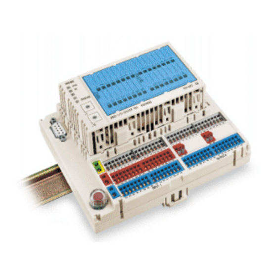
System Overview
Base Module Description
Describes the base module as the interface for external wiring, power, and sensor/actuator connections.
Electronic Module Description
Describes the plug-in electronic module containing processing, fieldbus interface, and I/O circuits.
Base Module Features and Connections
Details features like D-SUB connection, terminals for power, sensors, actuators, and clear labeling.
Electronic Module Features and Indicators
Highlights plug-in design, undisturbed wiring on replacement, and status indicators.
Marking Label Usage
Describes how to remove and insert the marking label for identification.
Technical Specifications
PROFIBUS DP System Parameters
Specifies system parameters like node count, I/O points, transmission medium, length, and baud rate.
Power Supply Specifications
Details supply voltage, current input, total power loss, and fuse rating.
General Technical Data
Covers dimensions, housing material, fixing, fitting position, and weight.
Wire Connection Specifications
Specifies wire connection types and sizes for power supply, sensors, and outputs.
Input Specifications
Details number of inputs, wire connection, signal voltage levels, and time constant.
Output Specifications
Covers number of outputs, rated voltage, current, leakage, short circuit protection, and diagnosis.
Protection Rating
Specifies protection rating according to EN 60 529.
Compliance and Certifications
Lists CE and UL certifications.
Environmental and Climatic Conditions
Outlines operating/storage temperature, humidity, air pressure, altitude, and strain.
Mechanical Resilience
Details vibration and impact resistance according to IEC standards.
Electrical Safety Standards
Covers reverse voltage protection, air/creepage distances, isolation, and test voltage.
Electromagnetic Compatibility (EMC)
Specifies interference resistance and emission according to EN standards.
Physical Dimensions and Clearances
Provides detailed dimensions and required clearances for installation.
Installation Clearance Requirements
Specifies clearances required for ventilation between modules and walls.
Installation Guide
Mechanical Mounting
Describes the physical mounting of the module.
Base Module Mounting and Removal
Details how to attach and remove the base module from the carrier rail.
Electronic Module Installation and Removal
Explains how to plug in and remove the electronic module from the base module.
Marking Label Procedures
Describes how to remove and insert the marking label for identification.
Setting the Station Address
Explains how to set the node address using the encoding switches.
Electrical Connection Guide
Covers the electrical connection aspects.
Module Supply Voltage Wiring
Details how to connect the 24V DC supply voltage and ground.
Input Signal Wiring
Explains how to connect sensor signals to the input terminals.
Sensor Wiring Examples
Shows how to connect 2-conductor and 3-conductor sensors to the input terminals.
Output Supply Voltage Wiring
Explains how to connect the supply voltage for output groups, both internally and externally.
Output Signal Wiring
Details how to connect actuators to the output terminals.
Fieldbus Interface Connection (D-SUB)
Describes the 9-pole D-SUB connector for PROFIBUS network interfacing.
Fieldbus Cabling and Standards
Covers PROFIBUS cabling specifications, line types, and parameters.
Fieldbus Cabling and Termination
Explains bus connection, termination, and the importance of integrated inductivity.
PROFIBUS Cabling Diagram
Illustrates a PROFIBUS cabling section with shielding and connection details.
Additional Cabling Resources
Provides links for additional PROFIBUS documentation and cable specifications.
Schematic Circuitry
Circuit Diagram Overview
Presents a schematic representation of input, output, and supply circuitry.
Status Indicators (LEDs)
Input Status LED Interpretation
Explains the LED behavior for input signal status based on voltage levels.
Output Status LED Interpretation
Details the LED indications for output states like ON, OFF, short circuit, and no supply.
Fieldbus Interface Status LEDs
Explains the RUN and BF (Bus Failure) status LEDs for the fieldbus interface.
Overload Fault Indicator
Describes the "OVERLOAD" LED and its possible causes like short circuits or output driver faults.
PROFIBUS Communication
PROFIBUS Overview
Provides an overview of PROFIBUS specifications and the module's role as a slave device.
GSD File Information
Explains the function of GSD files for PROFIBUS DP module configuration.
Parameterization Details
Details the expected parameter structure from the master, including standard and user parameters.
Input/Output Configuration
Explains how input and output configurations are defined using identifier bytes.
PROFIBUS Diagnosis
Describes standard and device status diagnosis, diagnostic bits DS1-DS4, and reasons for diagnostic messages.
Process Data Input Image Structure
Shows the structure of the input process data image, mapping bits to DIx.
Process Data Output Image Structure
Shows the structure of the output process data image, mapping bits to DOx.
Fieldbus Controller Boards
Mentions WAGO's controller boards and availability from other manufacturers.
Configuration Software Requirements
Discusses the need for configuration software and WAGO NETCON.
Optional Accessories
Accessory Product List
Lists available accessories for the I/O module, including GSD files, marking labels, fuses, and tools.
Technical Glossary
Glossary of Terms
Defines key terms and concepts related to the WAGO-I/O-SYSTEM 752 and PROFIBUS.
Need help?
Do you have a question about the 752-323 and is the answer not in the manual?
Questions and answers