Table of Contents
Advertisement
Quick Links
Advertisement
Table of Contents

Related Manuals for IDEC HR6S Series


Summary of Contents for IDEC HR6S Series
- Page 1 HR6S-AB HR9Z-B2190 Safety Module Original instructions http://www.idec.com...
- Page 2 You also agree not to establish any hypertext links to this document or its content. IDEC CORPORATION does not grant any right or license for the personal and noncommercial use of the document or its content, except for a non-exclusive license to consult it on an "as is" basis, at your own risk.
-
Page 3: Table Of Contents
Table of Contents Safety Information......About the Book ....... . Chapter 1 Introduction . - Page 4 Chapter 8 Accessories, Service, Maintenance, and Disposal..Accessories ..........Maintenance.
-
Page 5: Safety Information
Safety Information Important Information NOTICE Read these instructions carefully, and look at the equipment to become familiar with the device before trying to install, operate, service, or maintain it. The following special messages may appear throughout this documentation or on the equipment to warn of potential hazards or to call attention to information that clarifies or simplifies a procedure. - Page 6 PLEASE NOTE Electrical equipment should be installed, operated, serviced, and maintained only by qualified personnel. No responsibility is assumed by IDEC CORPORATION for any consequences arising out of the use of this material. A qualified person is one who has skills and knowledge related to the construction and operation of electrical equipment and its installation, and has received safety training to recognize and avoid the hazards involved.
- Page 7 Operate the product only with the specified cables and accessories. Use only genuine accessories. Any use other than the use explicitly permitted is prohibited and can result in hazards. HR9Z-B2190 8/2020...
- Page 8 HR9Z-B2190 8/2020...
-
Page 9: About The Book
About the Book At a Glance Document Scope This manual describes technical characteristics, installation, commissioning, operation and maintenance of the safety module HR6S-AB. Validity Note (see page 19) . The present document is valid for the products listed in the type code Related Documents Title of documentation Reference number... - Page 10 Product Related Information DANGER HAZARD OF ELECTRIC SHOCK, EXPLOSION OR ARC FLASH Disconnect all power from all equipment including connected devices prior to removing any covers or doors, or installing or removing any accessories, hardware, cables, or wires except under the specific conditions specified in the appropriate hardware guide for this equipment.
- Page 11 WARNING LOSS OF CONTROL The designer of any control scheme must consider the potential failure modes of control paths and, for certain critical control functions, provide a means to achieve a safe state during and after a path failure. Examples of critical control functions are emergency stop and overtravel stop, power outage and restart.
- Page 12 Terminology Derived from Standards The technical terms, terminology, symbols and the corresponding descriptions in this manual, or that appear in or on the products themselves, are generally derived from the terms or definitions of international standards. In the area of functional safety systems, drives and general automation, this may include, but is not limited to, terms such as safety , safety function , safe state , fault , fault reset , malfunction , failure , error , error message , dangerous , etc.
- Page 13 In addition, terms used in the present document may tangentially be used as they are derived from other standards such as: Standard Description IEC 60034 series Rotating electrical machines IEC 61800 series Adjustable speed electrical power drive systems IEC 61158 series Digital data communications for measurement and control –...
- Page 14 HR9Z-B2190 8/2020...
-
Page 15: Chapter 1 Introduction
Chapter 1 Introduction What Is in This Chapter? This chapter contains the following topics: Topic Page Device Overview Front View and Side View Nameplate Type Code HR9Z-B2190 8/2020... -
Page 16: Device Overview
Introduction Device Overview Outline The device is a safety module for interruption of safety-related electrical circuits. The device provides application functions used to monitor signals from different types of sensors/devices. Equipment with the following types of outputs can be connected to the safety-related inputs of the device: NO, NC, C/O, for example, Emergency Stop push-buttons, guard door switches, coded ... -
Page 17: Front View And Side View
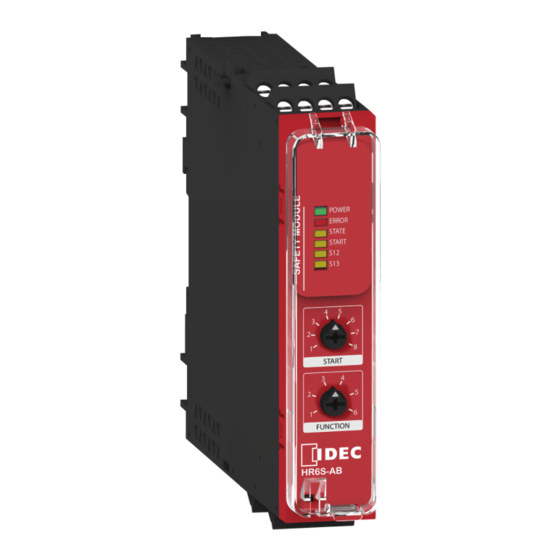
Introduction Front View and Side View Front View and Side View POWER ERROR STATE START START FUNCTION HR6S-AB 1 Removable terminal blocks, top 2 Removable terminal blocks, bottom 3 LED indicators 4 Start function selector 5 Application function selector 6 Sealable transparent cover HR9Z-B2190 8/2020... -
Page 18: Nameplate
Introduction Nameplate Nameplate HR6S Safety module The nameplate contains the following data: (see page 19) ) 1 Device type (refer to chapter Type Code 2 Nominal voltage 3 Frequency range VAC supply 4 Input power 5 Maximum current of safety-related outputs with utilization category AC-15 (250 VAC) 6 Maximum current of safety-related outputs with utilization category DC-13 (24 VDC) 7 Maximum total thermal current 8 Maximum Safety Integrity Level (SIL) as per IEC 61508-1:2010... -
Page 19: Type Code
HR6S: HR6S safety module 5 ... 6 Product version Supply voltage 1 = 24 VAC/VDC Terminal type C = Push-in terminals, removable P = Screw terminals, removable If you have questions concerning the type code, contact your IDEC CORPORATION service representative. HR9Z-B2190 8/2020... - Page 20 Introduction HR9Z-B2190 8/2020...
-
Page 21: Chapter 2 Technical Data
Chapter 2 Technical Data What Is in This Chapter? This chapter contains the following topics: Topic Page Environmental Conditions Mechanical Characteristics Electrical Characteristics Timing Data Data Functional Safety HR9Z-B2190 8/2020... -
Page 22: Environmental Conditions
Technical Data Environmental Conditions Environmental Conditions For Storage The device complies with class 1K5 as per IEC 60721-3-1 (climatic conditions): Characteristic Value Ambient temperature -40 ... 70 °C (-40 ... 158 °F) Rate of change of temperature 1 °C/min (1.8 °F/min) Ambient humidity 10 ... - Page 23 Technical Data Environmental Conditions For Operation Characteristic Value Maximum installation altitude above mean sea level 2000 m (6562 ft) Installation required in control cabinet/enclosure with IP54 degree of protection The device complies with class 3K5 and special class 3Z11 as per IEC 60721-3-3 (climatic conditions): Characteristic Value...
-
Page 24: Mechanical Characteristics
Technical Data Mechanical Characteristics Dimensions 22.5 4.61 0.89 a: *C max. 0.39 a: *P max. Characteristic Value HR6S-AB1C HR6S-AB1P Width 22.5 mm (0.89 in) Height without terminals 99 mm (3.9 in) Height with terminals 119 mm (4.7 in) 109 mm (4.3 in) Depth 117 mm (4.61 in) Weight... - Page 25 Technical Data Wire Cross Sections, Stripping Lengths, and Tightening Torques Characteristic Value Stripping length for Push-in terminals 12 mm (0.47 in) Stripping length for screw terminals 7 ... 8 mm (0.28 ... 0.31 in) Wire cross section, single wire without wire ferrule 0.2 ...
-
Page 26: Electrical Characteristics
Technical Data Electrical Characteristics Supply Characteristic Value Supply voltage AC 24 VAC (-15 ... 10 %) Supply voltage DC 24 VDC (-20 ... 20 %) Nominal input power AC 3.5 VA (24 VAC) Nominal input power DC 1.5 W (24 VDC) Frequency range AC 50 ... - Page 27 Technical Data Start Input Characteristic Value Output voltage at DC+ >15 VDC Input voltage at CH+ 0 ... 24 VDC (+20 %) Switching voltage activate CH+ >15 VDC Switching voltage deactivate CH+ <5 VDC Input current 5 mA Maximum wire resistance 500 Ω...
- Page 28 Technical Data Safety-Related Outputs Characteristic Value Number of relay contacts, changeover (Normally Closed to Normally Open), instantaneous Maximum short circuit current IK 1 kA Maximum continuous current, Normally Open relay contacts Maximum continuous current, Normally Closed relay contacts Maximum total thermal current ∑I Minimum current 10 mA Minimum voltage...
-
Page 29: Timing Data
Technical Data Timing Data Maximum Response Times Characteristic Value Maximum response time to request at safety-related input 20 ms Maximum response time after power outage AC 200 ms Maximum response time after power outage DC 120 ms Recovery Time Characteristic Value Recovery time after request at safety-related input 200 ms... - Page 30 Technical Data Debounce Time of Safety-Related Inputs Characteristic Value Debounce time, standard 2.5 ms Debounce time, with OSSD 4 ms Signal Interlock Monitoring Time Characteristic Value Signal interlock monitoring time 200 ms Synchronization Times The synchronization times for the synchronization of safety-related inputs depend on the application function (see page 56) .
-
Page 31: Data Functional Safety
Technical Data Data Functional Safety Data Functional Safety Characteristic Value Defined safe state Safety-related outputs are de-energized Normally Open: open Normally Closed: closed Maximum Performance Level (PL), Category PL c, Category 1 (as per ISO 13849-1:2015) Actual PL and category depend on wiring and configuration. - Page 32 Technical Data values as per ISO 13849 value Nominal current in A (see page 29) for additional technical data that may affect your Refer to chapter Timing Data functional safety calculations. HR9Z-B2190 8/2020...
-
Page 33: Chapter 3 Engineering
Chapter 3 Engineering What Is in This Chapter? This chapter contains the following topics: Topic Page Electromagnetic Compatibility (EMC) Basic Principles of Operation Safety-Related Inputs Synchronization of Safety-Related Inputs Dynamization Signal Interlock Monitoring HR9Z-B2190 8/2020... -
Page 34: Electromagnetic Compatibility (Emc)
Engineering Electromagnetic Compatibility (EMC) Conducted and Radiated Electromagnetic Emissions WARNING INSUFFICIENT ELECTROMAGNETIC COMPATIBILITY Verify compliance with all EMC regulations and requirements applicable in the country in which the device is to be operated and with all EMC regulations and requirements applicable at the installation site. -
Page 35: Basic Principles Of Operation
Engineering Basic Principles of Operation Introduction The following sections provide basic information on the principles of operation of the device to assist you in engineering your application function. Operating States The following graphic illustrates the operating states and state transitions of the device: Operating state Description In defined... - Page 36 Engineering State Transitions State transition Condition Power on Initialization successful Switch on delay has passed Start condition fulfilled (for example, automatic start or manual start with start button pressed) Safety-related inputs activated For application functions with signal interlock monitoring: no signal interlock ...
- Page 37 Engineering If the safety-related input is not activated (actuator of Emergency Stop pushbutton pushed down), the device remains in the operating state Run: Outputs Deenergized. The motor remains at a standstill. If the safety-related input is activated (actuator of Emergency Stop pushbutton pulled out), the device transitions to the operating state Run: Outputs Energized (T3).
- Page 38 Engineering Timing Diagram for Example with Emergency Stop The following timing diagram provides an overview of the example with Emergency Stop. Legend Item Description The safety-related input is activated (actuator of Emergency Stop button pulled out). The device remains in the defined safe state. ...
-
Page 39: Safety-Related Inputs
Engineering Safety-Related Inputs Overview WARNING INSUFFICIENT AND/OR INEFFECTIVE SAFETY-RELATED FUNCTIONS Only connect a sensor/device to a safety-related input that meets all requirements as per your risk assessment and that complies with all regulations, standards, and process definitions applicable to your machine/process. Failure to follow these instructions can result in death, serious injury, or equipment damage. - Page 40 Engineering One safety-related input with two input channels with antivalent behavior (magnetic switch with NO at S12 and NC at S13): If the level at terminal S12 is logically 0 and the level at terminal S13 is logically 1, the safety-related input is activated.
-
Page 41: Synchronization Of Safety-Related Inputs
Engineering Synchronization of Safety-Related Inputs Overview The device can monitor synchronized behavior of the two input channels of the safety-related input using various synchronization mechanisms with different synchronization times. If the two synchronized channels of the safety-related input are not activated within the synchronization time, the safety-related output is not deactivated. -
Page 42: Dynamization
Engineering Dynamization Dynamization of Inputs Dynamization is used for cross circuit detection between the control output and an input channel of the safety-related input or between the safety-related input and the Start input or a cross-circuit to an external power supply unit or to ground. Dynamization is implemented by means of periodically generated test pulses at the control outputs of the safety-related inputs S#1 and of the start input Y1. -
Page 43: Signal Interlock Monitoring
Engineering Signal Interlock Monitoring Overview Signal interlock is a monitoring function used to detect conditions in which one of the sensors/devices cannot provide the expected input signal for the device, for example, as a result of contact welding. The device expects “simultaneous” deactivation of the two input channels of the safety-related input within the signal interlock monitoring time of 200 ms. - Page 44 Engineering The following figure illustrates a condition with signal interlock: Safety-relaed input S## Safety-relaed input S## The first input channel of the safety-related input is deactivated which starts the signal interlock monitoring time of 200 ms. It is then activated again before the second input channel of the safety- related input is deactivated.
-
Page 45: Chapter 4 Installation
Chapter 4 Installation What Is in This Chapter? This chapter contains the following topics: Topic Page Prerequisites and Requirements Mechanical Installation Electrical Installation HR9Z-B2190 8/2020... -
Page 46: Prerequisites And Requirements
Installation Prerequisites and Requirements Inspecting the Device Damaged products may cause electric shock or unintended equipment operation. DANGER ELECTRIC SHOCK OR UNINTENDED EQUIPMENT OPERATION Do not use damaged products. Keep foreign objects (such as chips, screws or wire clippings) from getting into the product. ... -
Page 47: Mechanical Installation
Installation Mechanical Installation Mounting to DIN Rail The device can be mounted to the following DIN rails as per IEC 60715: 35 x 15 mm (1.38 x 0.59 in) 35 x 7.5 mm (1.38 x 0.29 in) 0.59 0.29 0.04 0.04... - Page 48 Installation Screw-Mounting 2 x Φ 4.3 M4 x 12 / 16 11.25 2 x Φ 0.17 M4 (ISO 7093) M4 x 0.47 / 0.63 0.44 Mounting procedure: Step Action Push the additional fastener into the grooves at the device. Prepare the holes on the mounting surface. Screw the device to the mounting surface using the specified screws and a washer M4 as per ISO 7093 for each screw.
-
Page 49: Electrical Installation
Installation Electrical Installation General Information DANGER FIRE, ELECTRIC SHOCK OR ARC FLASH Disconnect all power from all equipment of your machine/process prior to electrical installation of the device. Confirm the absence of power using a properly rated voltage sensing device. ... - Page 50 Installation Block Diagram and Terminals The following drawings present the block diagram and the terminals with their designations in the removable terminal blocks. Terminal Designation Explanation A1, A2 Power supply Control output (DC+) of start input Input channel (CH+) of start input HR9Z-B2190 8/2020...
- Page 51 Installation Terminal Designation Explanation Control output (DC+) of safety-related input Two terminals S11 are provided to facilitate wiring. Connect only one of the S11 terminals. S12, S13 Input channels (CH+) of safety-related input Depending on the selected application function, the safety-related input is used with terminals S11-S12 only or with terminals S11-S12-S13.
- Page 52 Installation Wire the terminals of the safety-related inputs according to the wiring diagram for the application (see page 56) to be implemented. function Safety-Related Outputs WARNING INCORRECT USE/WIRING OF SAFETY-RELATED OUTPUT Verify that the changeover output is not used for safety-related purposes if only terminals 11 ...
- Page 53 Installation The common reference potential is established via terminal B2. Respect the maximum wire resistance of 500 Ω when determining the cable length. The maximum wire length between the start input and a sensor/device is 30 m (98.43 ft) if the supply via the control output (terminal Y1) of the start input is not used.
- Page 54 Installation HR9Z-B2190 8/2020...
-
Page 55: Chapter 5 Functions
Chapter 5 Functions What Is in This Chapter? This chapter contains the following topics: Topic Page Application Functions Start Functions HR9Z-B2190 8/2020... -
Page 56: Application Functions
Functions Application Functions Introduction The following sections provide an overview of the available application functions and a detailed listing of requirements and values of each of the application functions. The chapter Configuration (see page 70) describes the configuration procedure by means of the selectors of the device. Overview of Application Functions Typical applications Type of outputs of sensor/device... - Page 57 Functions Application Function 1 Characteristic Value/Description Typical applications Monitoring of Emergency Stop circuits as per ISO 13850 and IEC 60204-1, stop category 0 Monitoring of guards as per ISO 14119/14120 with electrical switches Type of outputs of sensor/device providing the input signal Normally open, normally closed and/or changeover for application function outputs...
- Page 58 Functions Application Function 2 Characteristic Value/Description Typical applications Monitoring of two-hand control devices, type III A as per ISO 13851 Type of outputs of sensor/device providing the input signal Normally open, normally closed and/or changeover for application function outputs S## terminals to be connected S11-S12 and S11-S13 Dynamization Signal interlock monitoring...
- Page 59 Functions Application Function 3 Characteristic Value/Description Typical applications Monitoring of guards as per ISO 14119/14120 with electrical switches Monitoring of guards as per ISO 14119/14120 with coded magnetic switches Monitoring of proximity switches Type of outputs of sensor/device providing the input signal Normally open, normally closed and/or changeover for application function outputs...
- Page 60 Functions Application Function 4 Characteristic Value/Description Typical applications Monitoring of guards as per ISO 14119/14120 with electrical switches Monitoring of guards as per ISO 14119/14120 with coded magnetic switches Monitoring of proximity switches Type of outputs of sensor/device providing the input signal Normally open, normally closed and/or changeover for application function outputs...
- Page 61 Functions Application Function 5 Characteristic Value/Description Typical applications Monitoring of proximity switches Type of outputs of sensor/device providing the input signal One PNP output for application function S## terminals to be connected Signals at terminal S13 are not evaluated. Do not connect this terminal.
- Page 62 Functions Application Function 6 Characteristic Value/Description Typical applications Monitoring of electro-sensitive protective equipment such as type 4 light curtains as per IEC 61496-1 Monitoring of RFID sensors Type of outputs of sensor/device providing the input signal OSSD (Output Signal Switching Device) outputs for application function S## terminals to be connected S12 and S13...
-
Page 63: Start Functions
Functions Start Functions Overview WARNING UNINTENDED EQUIPMENT OPERATION Do not use the Start function for safety-related purposes. Use Monitored Start or Startup Test if unintended restart is a hazard according to your risk assessment. Failure to follow these instructions can result in death, serious injury, or equipment damage. The device provides several start functions which are selected by means of the start function selector. - Page 64 Functions Automatic Start With automatic start, the start input is permanently active. This can be achieved by bridging the start input or providing an external power supply. When the safety-related input is activated, the safety-related output is activated within a maximum of 100 ms (activation delay). The following timing diagram illustrates the automatic start: Activation delay (100 ms): maximum time between activation of safety-related input and activation of safety-related output...
- Page 65 Functions Manual Start A manual start requires the start input to be activated. The safety-related output is activated after both the start input and the safety-related input have been activated. The following timing diagram illustrates the manual start: Activation delay (100 ms): maximum time between activation of start input and activation of safety-related output Response time (20 ms): maximum time between deactivation of safety-related input and deactivation of safety-related output...
- Page 66 Functions Monitored Start with Falling Edge In the case of a monitored start with falling edge, the start input must be activated and remain active for a duration of 80 ms. The safety-related outputs are activated with a falling edge of the start input if the safety-related inputs have been activated in the meantime.
- Page 67 Functions Startup Test The startup test is performed after the device is powered on. The startup test is typically used for applications involving guard monitoring. The start input is permanently activated by, for example, bridging. After power-on, the safety-related input must be deactivated and activated before the safety-related output is activated.
- Page 68 Functions Configuring the Start Function The start function is configured by means of the start function selector. Position of start function selector Configured start function Automatic/manual start (depends on sensor/device connected to start input) Without startup test With dynamization ...
-
Page 69: Chapter 6 Configuration And Commissioning
Chapter 6 Configuration and Commissioning What Is in This Chapter? This chapter contains the following topics: Topic Page Configuration Commissioning HR9Z-B2190 8/2020... -
Page 70: Configuration
Configuration and Commissioning Configuration Overview The device detects certain technically incorrect configurations (for example, a configured start function cannot be used with a configured application function). The device cannot detect unwanted configurations (for example, automatic start has been configured, but a monitored start is required for your application as a result of your risk assessment). - Page 71 Configuration and Commissioning Configuration Procedure Step Action Verify that the device has been wired according to the safety-related function to be configured. Remove power if the device is not powered off. Open the transparent cover of the device. Set the application function selector to the required application function. Set the start function selector to the required start function.
-
Page 72: Commissioning
Configuration and Commissioning Commissioning Overview WARNING INEFFECTIVE SAFETY-RELATED FUNCTION AND/OR UNINTENDED EQUIPMENT OPERATION Commission the device before it is used for the first time and after each configuration. Commission or recommission the machine/process pursuant to all regulations, standards, and ... -
Page 73: Chapter 7 Diagnostics
Chapter 7 Diagnostics WARNING INEFFECTIVE SAFETY-RELATED FUNCTION AND/OR UNINTENDED EQUIPMENT OPERATION Only attempt to resolve alerts and errors detected by the device if you are fully familiar with the safety-related applications and the non-safety-related applications as well as the hardware used to operate your machine/process. -
Page 74: Diagnostics Via Leds
Diagnostics Diagnostics via LEDs Overview (see page 17) that provide status information and information The device features various LEDs on alerts and detected errors. Recommission the device (see page 72) if, during troubleshooting, you modify the position of the application function selector, the start function selector. LED POWER State Meaning... - Page 75 This LED flashes in conjunction with additional S## LEDs to indicate alerts. In the case of an alert, the device transitions to the defined safe state. Remove the cause of the alert to exit the defined safe state and resume operation. Contact your IDEC CORPORATION service representative if the condition persists.
- Page 76 You must remove the cause of the detected error and perform a power cycle of the device to exit the defined safe state and resume operation. Contact your IDEC CORPORATION service representative if the condition persists.
-
Page 77: Diagnostics Via Status Output Z1
Diagnostics Diagnostics via Status Output Z1 Overview WARNING INCORRECT USE OF OUTPUT Do not use the additional output Z1 for safety-related purposes. Failure to follow these instructions can result in death, serious injury, or equipment damage. The pulsed output Z1 provides diagnostics information in the form of a bit pattern. (see page 53) for additional information on wiring the Z1. - Page 78 Diagnostics Bit sequence Description Correctives Type 0010001100 Cross circuit detected at Verify correct wiring. input terminal S12. Verify that the sensor/device providing the input signal is suitable for cross circuit detection by means of dynamization. If it is not, use an application function without dynamization or a sensor/device suitable for dynamization.
- Page 79 Diagnostics Bit sequence Description Correctives Type 0010110101 Input S12 is expected to change its state. In the case of a configuration with antivalent inputs, inputs S12 and S13 are expected to change their states. 0010110100 Input S13 is expected to change its state.
- Page 80 Diagnostics HR9Z-B2190 8/2020...
-
Page 81: Chapter 8 Accessories, Service, Maintenance, And Disposal
Chapter 8 Accessories, Service, Maintenance, and Disposal What Is in This Chapter? This chapter contains the following topics: Topic Page Accessories Maintenance Transportation, Storage, and Disposal Service Addresses HR9Z-B2190 8/2020... -
Page 82: Accessories
Accessories, Service, Maintenance, and Disposal Accessories Accessories The following accessories are available for the device: Description Type number Coding bits HR9Z-EC The coding bits are used if the terminal blocks are removed to help ensure correct insertion of the terminal blocks into the device. 30 pieces per packaging unit Sealing strips HR9Z-ES... -
Page 83: Maintenance
Accessories, Service, Maintenance, and Disposal Maintenance Service and Repairs The device contains no user-serviceable parts. Do not attempt to open, service, or repair the device. Maintenance Plan Maintenance plan: Ensure that a safety-related function implemented with the device is triggered at the minimum ... -
Page 84: Transportation, Storage, And Disposal
Accessories, Service, Maintenance, and Disposal Transportation, Storage, and Disposal Transportation and Storage (see page 22) specified for transportation and storage Ensure that the environmental conditions are respected. Disposal Dispose of the product in accordance with all applicable regulations. HR9Z-B2190 8/2020... -
Page 85: Service Addresses
● B-2190 (0) ● August, 2020 ● 2-6-64 Nishimiyahara, Yodogawa-ku, Osaka, 532-0004 Japan IDEC CORPORATION ©2020 IDEC CORPORATION All Rights Reserved. - The specifications and other information herein are subject to change without notice. - All rights reserved. HR9Z-B2190 8/2020... - Page 86 Accessories, Service, Maintenance, and Disposal HR9Z-B2190 8/2020...
-
Page 87: Index
Index electromagnetic compatibility, 34 EMC, 34 accessories, 82 Emergency Stop circuits as per ISO 13850 activation, safety-related inputs, 39 and IEC 60204-1, stop category 0, monitoring alerts, 74 of, 57 antivalent behavior, safety-related inputs, 39 environmental characteristics, 22 application functions errors, detected, 74 configuration, 70 example Emergency Stop... - Page 88 Index monitoring of two-hand control devices, monitored start with falling edge, 66 type III A as per ISO 13851, 58 monitoring of electro-sensitive protective overview application functions, 56 equipment (type 4 light curtains) as per signal interlock monitoring, 43 IEC 61496-1, 62 start functions, 63 monitoring of Emergency Stop circuits as per synchronization of safety-related inputs,...
- Page 89 Index status output Z1 power supply diagnostics, 77 technical data, 26 technical data, 28 wiring, 53 wiring, 53 proximity switches, monitoring of, 59 , 60 , 61 , stop category, 31 storage, environmental characteristics, 22 stripping lengths, 25 supply response times technical data, 26 technical data, 29 wiring, 53...
- Page 90 Index view front view, 17 side view, 17 weight, 24 wire cross sections, 25 wiring, 49 output Z1, 53 power supply, 53 safety-related inputs, 51 safety-related outputs, 52 start input, 52 supply, 53 Z1 status output diagnostics, 77 technical data, 28 wiring, 53 ZVEI CB24I, 27 HR9Z-B2190 8/2020...
- Page 91 China/Shanghai IDEC (Shanghai) Corporation Tel: +86-21-6135-1515 idec@cn.idec.com Singapore IDEC Izumi Asia Pte. Ltd. Tel: +65-6746-1155 info@sg.idec.com China/Shenzhen IDEC (Shenzhen) Corporation Tel: +86-755-8356-2977 idec@cn.idec.com Thailand IDEC Asia (Thailand) Co., Ltd Tel: +66-2-392-9765 sales@th.idec.com China/Beijing IDEC (Beijing) Corporation Tel: +86-10-6581-6131 idec@cn.idec.com Australia IDEC Australia Pty. Ltd.