Table of Contents
Advertisement
Quick Links
Advertisement
Table of Contents

Related Manuals for IDEC LONWORKS


Summary of Contents for IDEC LONWORKS
- Page 1 FL 9Y- B6 95 ® ORKS Communication Module User's Manual...
- Page 2 Safety Notices Indicates that death, severe bodily injury or substantial material damage will occur, if the corresponding safety measures are not taken. DANGER Indicates that death or severe bodily injury may occur, if the corresponding safety measures are not taken. WARNING With the warning triangle, this indicates that minor bodily...
- Page 3 Copyright © IDEC IZUMI CORPORATION All rights reserved You may not transfer or duplicate this document or utilize or reveal its contents, unless expressly authorized in writing. In the case of a violation, you will be obliged to pay damages. All rights reserved, in particular in the event that a patent is granted or that a utility model is registered.
-
Page 4: Table Of Contents
Table of Contents Getting to know LONWORKS® Communication Module..1-1 What is LONWORKS® Communication Module ? ....1-1 The construction of the LONWORKS® Communication Module1-2 Mounting and wiring the LONWORKS® Communication Module…2-1 General guidelines ..............2-1 Wiring the LONWORKS® Communication Module ....2-3 2.2.1... -
Page 5: Getting To Know Lonworks® Communication Module
The L ® Communication Module presents the ORKS current states of the LON stations to the IDEC SmartRelay, which is thus able to use its logical functions and timers to join them together. In the process, the LON signals can also be combined with the signals of the local IDEC SmartRelay inputs and outputs. -
Page 6: The Construction Of The Lonworks® Communication Module1-2
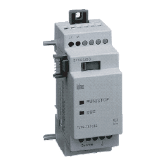
1.2 The construction of the L ® ORKS Communication Module ® Communication Module User’s Manual ORKS Phone: 800.894.0412 - Fax: 888.723.4773 - Web: www.clrwtr.com - Email: info@clrwtr.com... - Page 7 1. Power supply 2. Bus lock slider, interface to the IDEC SmartRelay 3. The RUN/STOP LED for IDEC SmartRelay communication 4. The SERVICE LED 5. Input - LON connection 6. Expansion interface to the IDEC SmartRelay 7. Mechanical coding - pin 8.
-
Page 8: Mounting And Wiring The Lonworks® Communication Module
The L ® Communication Module must always ORKS be installed as the last module on the right of the IDEC SmartRelay, since you may not install other expansion modules onto the L ® Communication Module. - Page 9 This module may only be mounted and wired by qualified personnel, who know and observe the generally applicable guidelines and applicable regulations and standards. Observe the assembly and disassembly instructions in the IDEC SmartRelay manual. WARNING The expansion module may only inserted or removed when the power is off.
- Page 10 2.2 Wiring the L ® Communication ORKS Module To wire the L ® Communication Module, use a ORKS screwdriver with 3 mm wide blade. - You do not need to use wire end ferrules when clamping the wires. NOTE After the installation, the terminals must be covered. To protect personnel against unintentional contact with the portions of the L ®...
-
Page 11: Connecting The Power Supply
The L ® Communication Module has been ORKS designed to serve as a Slave module for the IDEC SmartRelay controller. It must be connected to a 24 V AC/DC supply voltage. Please observe the relevant instructions that are found in the... -
Page 12: Connecting The Lon
2.2.2 Connecting the LON This connection is made using the two screw terminals A-B. You can start the programming by pressing the “Service ¯” button. NOTE Don't apply force when pressing the “Service ¯” button. When contact has been made, the LED will light up in orange. -
Page 13: Step-By-Step
A LONMARK certified application was loaded into the LON module at the factory. 3.1 Step-by-step 1. Interrupt the voltage to the IDEC SmartRelay. (The IDEC SmartRelay and its modules do not have power switches.) 2. Mount the L ® Communication Module ORKS 3. - Page 14 3.2 The L ® Communication Module - ORKS operational status The L ® Communication Module is a IDEC ORKS SmartRelay expansion module. This module has two LED displays: “RUN/STOP” LED Communication with the IDEC SmartRelay “SERVICE” LED Service LED LED “RUN/STOP” Lights In...
-
Page 15: Behavior In Case Of A Fault
3.3 Behavior in case of a fault IDEC SmartRelay - Power failure If the power to the IDEC SmartRelay fails or the communications with the IDEC SmartRelay Master or the communications partner to the left is interrupted, the outputs will be set to 0. The “RUN/STOP” LED will light in RED after one second. -
Page 16: Supported Functions
Supports virtual inputs and outputs for the communication via the LON. 4.1 Virtual inputs / outputs The standard L ® Communication Module ORKS application fills the complete IDEC SmartRelay process image. A1 A2 I1 I2 I3 I4 I5 I6 I7 I8 FL1B-H12RCE FL1B-CL1C12 A3 ... - Page 17 Q5 Q6 Q7 Q8 I13 ... I24 Q9 ... Q16 1. To map the IDEC SmartRelay inputs (I1 to I8/I12) as outputs on the BUS, these must be joined with free virtual BUS outputs (Q5/Q9 to Q12) in the IDEC SmartRelay application.
-
Page 18: Available Network Variables
4.2 Available network variables The L ® Communication Module’s standard LON ORKS application contains the network variables described below. LonMark Node Object Quantity Name Type Description nviRequest0 SNVT_obj_request Request object mode nvoStatus0 SNVT_obj_status Output object status LonMark Controller Object SNVT Description SNVT_switch Switch light, alarm, window contact, free inputs / outputs... - Page 19 Assignment of the SNVT to the inputs and outputs SNVT Name Assignment Digital SNVT_switch nvoSwitchDO051 outputs nvoSwitchDO061 nvoSwitchDO071 nvoSwitchDO081 nvoSwitchDO091 nvoSwitchDO101 nvoSwitchDO111 nvoSwitchDO121 SNVT_occupancy nvoOccDO131 nvoOccDO141 SNVT_tod_event nvoTodDO151 nvoTodDO161 Digital inputs SNVT_switch nviSwitchDI091 nviSwitchDI101 nviSwitchDI111 nviSwitchDI121 nviSwitchDI131 nviSwitchDI141 nviSwitchDI151 nviSwitchDI161 nviSwitchDI171 nviSwitchDI181 nviSwitchDI191...
-
Page 20: Lon Configuration Parameters
4.3 LON configuration parameters All of the digital outputs are configured with a “Send Heartbeat”. The LON application is configured using the Config Network Variables. The following SCPT are available. SCPT Description Name Assignment Default SCPTmaxSendTime Send Heartbeat cpMaxSendTDO05 Q5 0 min SCPTmaxSendTime Send Heartbeat cpMaxSendTDO06 Q6 0 min... -
Page 21: Inputs / Outputs - Special Considerations
IDEC SmartRelay application with free virtual BUS inputs. To map the IDEC SmartRelay inputs (I1 - I8) as outputs on the BUS, these must be joined with free virtual BUS outputs in the IDEC SmartRelay application. - Page 22 85g Mounting options 35 mm rail wall mounting Connections IDEC SmartRelay connection Standard expansion interface For IDEC SmartRelay 12/24 V and 100/240 V LON connection (TP/FT-10) 2 screw terminals (0.5 – 2.5 mm²) Max. torque 0.5 Nm Power supply 2 screw terminals (0.5 –...
- Page 23 VDE 0631 IEC 61131-2 Overvoltage protection Fuse 80 mA slow action fuse Order Data IDEC SmartRelay Expansion Module FL1B-CL1C12 ® Communication Module ORKS ® Communication Module User’s Manual ORKS Phone: 800.894.0412 - Fax: 888.723.4773 - Web: www.clrwtr.com - Email: info@clrwtr.com...
- Page 24 Index Mechanical coding - pin ..1-3 SNVT_lux ......4-3 Power supply ....... 1-3 SNVT_obj_request ....4-3 RUN/STOP LED....1-3 SNVT_obj_status ....4-3 Service button...... 1-3 SNVT_occupancy ..4-3, 4-4 SERVICE LED ....1-3 SNVT_switch ....4-3, 4-4 slider ........1-3 SNVT_temp_p ....4-3, 4-4 SNVT_lev_percent..4-3, 4-4 SNVT_tod_event ...4-3, 4-4 ®...
Need help?
Do you have a question about the LONWORKS and is the answer not in the manual?
Questions and answers