IDEC MicroSmart Pentra FC5A Series User Manual
Expansion rs232c communication module
Hide thumbs
Also See for MicroSmart Pentra FC5A Series:
- Replacement manual (46 pages) ,
- User manual (343 pages)

Related Manuals for IDEC MicroSmart Pentra FC5A Series


Summary of Contents for IDEC MicroSmart Pentra FC5A Series
- Page 1 FC9Y-B969 FC5A SERIES Expansion RS232C Communication Module FC5A-SIF2 User’s Manual...
- Page 2 FC5A series MicroSmart expansion RS232C communication module • All MicroSmart modules are manufactured under IDEC’s rigorous quality control system, but users must add a backup or failsafe provision to the control system using the MicroSmart in applications where heavy damage or personal injury may be caused in case the MicroSmart should fail.
- Page 3 Under no circumstances shall IDEC Corporation be held liable or responsible for indirect or consequential damages resulting from the use of or the application of IDEC PLC components, individually or in combination with other equipment. All persons using these components must be willing to accept responsibility for choosing the correct component to suit their application and for choosing an application appropriate for the component, individually or in combination with other equipment.
-
Page 4: Table Of Contents
ABLE OF ONTENTS HAPTER ENERAL NFORMATION About the Expansion Communication Module ......1-1 Features . -
Page 5: About The Expansion Communication Module
1: G ENERAL NFORMATION Introduction This chapter describes general information and specifications of the FC5A series MicroSmart expansion RS232C commu- nication module. About the Expansion Communication Module The FC5A-SIF2 expansion RS232C communication module is an expansion module used for the FC5A series micro pro- grammable controller. -
Page 6: Applicable Cpu Modules And Windldr Version
1: G ENERAL NFORMATION Applicable CPU Modules and WindLDR Version The expansion RS232C communication module can be used with the FC5A MicroSmart CPU modules and WindLDR as listed below. All-in-one Type: FC5A-C24R2, FC5A-C24R2C CPU Modules Slim Type: FC5A-D16RK1, FC5A-D16RS1, FC5A-D32K3, FC5A-D32S3 System Program Version: 110 or later WindLDR... -
Page 7: Module Specifications
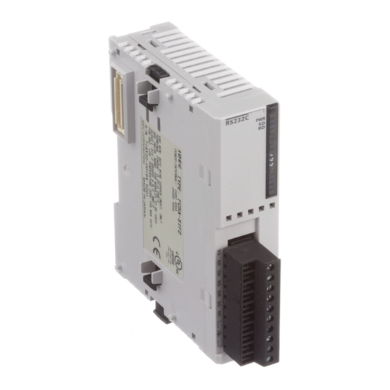
2: M ODULE PECIFICATIONS Introduction This chapter describes parts names, functions, specifications, and dimensions of the expansion RS232C communication module. Parts Description (1) Expansion Connector (2) Module Label (3) LED Indicator (4) Terminal Name (5) Cable Terminal (1) Expansion Connector Connects to the CPU and other I/O modules. - Page 8 2: M ODULE PECIFICATIONS Expansion RS232C Communication Module Specifications General Specifications Type No. FC5A-SIF2 Quantity of Channels Synchronization Start-stop synchronization Electrical Characteristics EIA RS232C compliant Terminal Arrangement See page 3-6. Operating Temperature 0 to 55°C Relative Humidity 10 to 95% (no condensation) Shielded multi-core cable: 24AWG x 6 Recommended Cable Specifications...
- Page 9 2: M ODULE PECIFICATIONS Data Communication Processing Time The CPU module processes data communication with expansion RS232C communication modules in every scan. One expansion RS232C communication module requires a communication processing time shown in the table below. There- fore, when an expansion RS232C communication module sends or receives communication, the scan time extends accord- ingly.
-
Page 10: Dimensions
2: M ODULE PECIFICATIONS Dimensions All MicroSmart modules have the same profile for consistent mounting on a DIN rail. 23.5 14.6 70.0 *8.5 mm when the clamp is pulled out. All dimensions in mm. FC5A E RS232C C ’ XPANSION OMMUNICATION ODULE ANUAL... -
Page 11: Nstallation And
3: I NSTALLATION AND IRING Introduction This chapter describes precautions for installing the expansion RS232C communication module in connection with the internal current draw by other expansion modules. For general methods and precautions for installation and wiring of the expansion RS232C communication module, see the FC5A MicroSmart user’s manual (FC9Y-B927). -
Page 12: Maximum Quantity Of Applicable Expansion Modules
3: I NSTALLATION AND IRING Maximum Quantity of Applicable Expansion Modules The all-in-one 24-I/O type CPU module can mount a maximum of three expansion RS232C communication modules. The slim type CPU module can mount a maximum of five expansion RS232C communication modules. Including expansion RS232C communication modules and other expansion modules, the all-in-one type CPU module can mount a maximum of four expansion modules, and the slim type CPU module can mount a maximum of seven expansion modules, unless the total internal current draw by all connected expansion modules exceeds the allowable current draw of... - Page 13 3: I NSTALLATION AND IRING Example: Installing five expansion RS232C communication modules to the slim type CPU module Internal Current Draw Total Internal Module Type No. Quantity (5V DC) Current Draw Expansion RS232C Communication Module FC5A-SIF2 85 mA 425 mA Maximum Applicable Expansion Modules (Slim CPU) —...
- Page 14 3: I NSTALLATION AND IRING Mounting Hole Layout for Direct Mounting on Panel Surface Using Direct Mounting Strip To mount the expansion RS232C communication module 23.5 Direct Mounting Strip on a panel surface, use the direct mounting strip and two FC4A-PSP1P M4 screws (6 or 8 mm long).
-
Page 15: Terminal Connection
3: I NSTALLATION AND IRING Terminal Connection • Do not touch live terminals, otherwise electrical shocks may be caused. Caution • Do not touch terminals immediately after power has been turned off, otherwise electrical shocks may be caused. • When using ferrules, insert a wire to the bottom of the ferrule and crimp the ferrule. •... -
Page 16: Terminal Arrangement And Wiring Diagram
3: I NSTALLATION AND IRING Terminal Arrangement and Wiring Diagram Screw Terminal Type Applicable Terminal Block: FC4A-PMT10P (supplied with the input module) RS232C Terminal Description RS (RTS) Output Request to Send (constant voltage terminal) ER (DTR) Output Data Terminal Ready SD (TXD) Output Transmit Data... -
Page 17: Allocating Communication Port Number
4: E RS232C C XPANSION OMMUNICATION Introduction This chapter describes communication examples using the expansion RS232C communication module. Allocating Communication Port Number When expansion RS232C communication modules are mounted, port number starts with port 3 and ends with port 7 when a maximum of five expansion RS232C communication modules are mounted. -
Page 18: Computer Link Communication
4: E RS232C C XPANSION OMMUNICATION Computer Link Communication The computer link communication can be used with WindLDR on a PC connected to the CPU module to perform mainte- nance operations, such as download/upload user programs, start/stop the PLC, monitor the PLC status, and read/write operand values. - Page 19 4: E RS232C C XPANSION OMMUNICATION Computer Link Communication through the Expansion RS232C Communication Module To perform the computer link communication using the expansion RS232C communication module, a user program has to be downloaded through port 1 or 2 in the 1:1 computer link system as shown on page 4-2, because user programs cannot be downloaded or uploaded through the expansion RS232C communication module.
- Page 20 4: E RS232C C XPANSION OMMUNICATION The Communication Parameters dialog box closes and the Communication page becomes active. 6. Click the OK button to save changes to the Function Area Settings. The Function Area Settings dialog box closes and the ladder editing screen becomes active. Next, download the user program through port 1 or 2 to the CPU module.
-
Page 21: Operator Interface Communication
OMMUNICATION Operator Interface Communication Using the expansion RS232C communication module, the MicroSmart can communicate with IDEC’s HG series operator interfaces. To connect the HG series operator interface to the expansion RS232C communication module, use a communi- cation cable prepared by the user. - Page 22 4: E RS232C C XPANSION OMMUNICATION Expansion RS232C Communication Module Communication Parameter Range Parameter Optional Range Default Communication Mode Maintenance communication Baud Rate (bps) 1200, 2400, 4800, 9600, 19200, 38400 9600 Data Bits 7 or 8 Parity Even, Odd, None Even Stop Bits 1 or 2...
-
Page 23: User Communication
4: E RS232C C XPANSION OMMUNICATION User Communication The user communication function can be used for the MicroSmart to communicate with a PC, printer, and barcode reader through the expansion RS232C communication module. For details about the user communication function, see the FC5A MicroSmart user’s manual (FC9Y-B927). - Page 24 4: E RS232C C XPANSION OMMUNICATION 5. The Communication Parameters dialog box appears. Change settings to meet the communication parameters of the remote device. See the user’s manual for the remote device. 1200, 2400, 4800, 9600, 19200, Baud Rate (bps) 38400 Data Bits 7 or 8...
- Page 25 4: E RS232C C XPANSION OMMUNICATION System Setup for Connecting a Printer Expansion RS232C Communication Module CPU Module FC5A-SIF2 RS232C The communication cable is prepared by the user referring to the diagram shown below. Printer For the wiring precautions, see page 3-6. 24VDC –...
- Page 26 4: E RS232C C XPANSION OMMUNICATION Setting Communication Parameters Set the communication parameters to match those of the printer. See page 4-8. For details of the communication parame- ters of the printer, see the user’s manual for the printer. An example is shown below: Communication Parameters: Baud rate 9600 bps...
-
Page 27: Communication Mode Information And Rs232C Line Control Signals
4: E RS232C C XPANSION OMMUNICATION Communication Mode Information and RS232C Line Control Signals Special data registers are allocated for communication mode information of port 1 through port 7 and RS232C line control signals for port 2 through port 7. While the MicroSmart is in the user communication mode, special data registers can be used to enable or disable DSR and DTR control signal options for port 2 through port 7. - Page 28 4: E RS232C C XPANSION OMMUNICATION Control Signal Status D8104 (Port 2 to Port 6) and D8204 (Port 7) Special data registers D8104 and D8204 store a value to show that DSR and DTR are on or off at port 2 through port 7. The data of D8104 and D8204 are updated at every END processing.
- Page 29 4: E RS232C C XPANSION OMMUNICATION DSR Input Control Signal Option D8105 (Port 2 to Port 6) and D8205 (Port 7) Special data registers D8105 and D8205 are used to control data flow between the MicroSmart RS232C port 2 through port 7 and the remote terminal depending on the DSR (data set ready) signal sent from the remote terminal.
- Page 30 4: E RS232C C XPANSION OMMUNICATION DTR Output Control Signal Option D8106 (Port 2 to Port 6) and D8206 (Port 7) Special data registers D8106 and D8206 are used to control the DTR (data terminal ready) signal to indicate the Micro- operating status or transmitting/receiving status.
-
Page 31: Txd (Transmit)
4: E RS232C C XPANSION OMMUNICATION TXD (Transmit) When input is on, data designated by S1 is converted into a specified format and transmitted from port 1 through port 7 to a remote terminal ***** ***** ***** with an RS232C port. TXD2 can be used to communicate with an RS485 remote terminal through port 2. -
Page 32: Rxd (Receive)
4: E RS232C C XPANSION OMMUNICATION RXD (Receive) When input is on, data from an RS232C remote terminal received by port 1 through port 7 is converted and stored in data registers according to ***** ***** ***** the receive format designated by S1. RXD2 can be used to communicate with an RS485 remote terminal through port 2. -
Page 33: Comrf (Communication Refresh)
4: E RS232C C XPANSION OMMUNICATION COMRF (Communication Refresh) The COMRF instruction refreshes the send and receive data in the expansion RS232C communica- COMRF tion buffers for port 3 through port 7 in real time. The send data in the buffer are usually sent out in the END processing. The receive data in the buffer are usually sent to MicroSmart operands in the END processing. - Page 34 4: E RS232C C XPANSION OMMUNICATION 4-18 FC5A E RS232C C ’ XPANSION OMMUNICATION ODULE ANUAL...
-
Page 35: Roubleshooting
This chapter describes the procedures to determine the cause of trouble and actions to be taken when any trouble occurs while operating the expansion RS232C communication module. When a trouble occurred, check the points and take the actions described below. If the trouble cannot be solved, call IDEC for assistance. The PWR (power) LED does not go on. - Page 36 5: T ROUBLESHOOTING Check Action Page Is the start input for the TXD instruction on? Turn on the start input for the TXD instruction. 4-15 Is the PWR LED on the CPU module on? See “The PWR (power) LED does not go on.” Data is not transmitted correctly in the user communication.
- Page 37 NDEX advanced instruction maintenance COMRF communication 4-17 protocol 4-16 maximum quantity of applicable expansion modules 4-15 allocating communication port number module specifications applicable mounting hole layout for direct mounting CPU modules operator interface communication expansion module maximum quantity WindLDR version parts description Phoenix busy...
- Page 38 Tel: +886-2-2698-3929 Fax: +886-2-2698-3931 E-mail: service@tw.idec.com SINGAPORE IDEC IZUMI ASIA PTE. LTD. No. 31, Tannery Lane #05-01 Dragon Land Building, Singapore 347788 Tel: +65-6746-1155 Fax: +65-6844-5995 E-mail: info@sg.idec.com www.idec.com ©2006 IDEC CORPORATION. All Rights Reserved. Manual No. FC9Y-B969-0 01/07 B-969(2)
- Page 39 Mouser Electronics Authorized Distributor Click to View Pricing, Inventory, Delivery & Lifecycle Information: IDEC FC5A-C24R2C FC5A-D16RK1 FC5A-D16RS1 FC5A-C24R2 FC5A-SIF2 FC5A-C24R2D FC5A-D32S3 FC5A- C10R2 FC5A-C16R2C FC5A-C16R2D FC5A-C10R2C FC5A-C16R2 FC5A-C10R2D FC5A-D32K3...
Need help?
Do you have a question about the MicroSmart Pentra FC5A Series and is the answer not in the manual?
Questions and answers