
Related Manuals for IDEC SmartRelay FL1D Series


Summary of Contents for IDEC SmartRelay FL1D Series
- Page 1 ngineering, Inc. ● 230 Ryan Way, South San Francisco, CA 94080-6370 ● General Inquiries: (800) 670-4183 ● www.st...
- Page 2 We thank you for purchasing IDEC SmartRelay and congrat- ulate you on your decision. IDEC SmartRelay can be used in many fields of applications. Due to its high functionality and yet easy operation the IDEC SmartRelay offers you utmost efficiency for almost any ap- plication.
- Page 3 Preface Valid range of this manual The manual applies to devices of the series FL1D. Changes compared to previous releases of the manual • The analog module IDEC SmartRelay FL1D-K2B2 was added. • The communication module FL1B-CAS2 was added. •...
- Page 4 IDEC SmartRelay Manual ngineering, Inc. ● 230 Ryan Way, South San Francisco, CA 94080-6370 ● General Inquiries: (800) 670-4183 ● www.ste...
- Page 5 Prerequisite for the safe and proper operation of the product is its proper transportation, storage, installation and mounting, and care- ful operator control and maintenance. Copyright © IDEC CORPORATION All rights reserved The reproduction, distribution or use of this document or its contents is not permitted without express written authority.
-
Page 6: Table Of Contents
Blocks and block numbers ..........57 The way to IDEC SmartRelay, starting with the circuit diagram................. 60 The four golden rules for operating IDEC SmartRelay ..63 Overview of IDEC SmartRelay menus ....... 65 Writing and starting the circuit program ......66 3.6.1... - Page 7 3.6.5 Password ................76 3.6.6 Switching IDEC SmartRelay to RUN mode ......81 3.6.7 Second circuit program ............84 3.6.8 Deleting a block ..............91 3.6.9 Deleting block groups ............92 3.6.10 Correcting programming errors........... 93 3.6.11 Selecting analog output values for RUN/STOP transition... 93 3.6.12 Deleting the circuit program ..........
- Page 8 5.1.1 Parameters ............... 232 5.1.2 Selecting the parameters..........233 5.1.3 Modifying parameters ............234 Setting the default values for IDEC SmartRelay ..... 237 5.2.1 Setting the time-of-day and date (FL1D-H12RC...) ..237 5.2.2 Setting the display contrast..........239 5.2.3 Setting the start screen............. 240 IDEC SmartRelay memory cartridge (card) ..241...
- Page 9 Copying data from the IDEC SmartRelay to the memory cartridge (card)..............248 Copying data from the memory cartridge (card) to IDEC SmartRelay ................. 250 IDEC SmartRelay software ......252 Connecting IDEC SmartRelay to a PC ......255 Applications..........257 Stairway or corridor lighting..........259 8.1.1...
- Page 10 Previous solution .............. 288 8.7.3 Service water pump system with FL1D-H12RCC..... 289 8.7.4 Special features and expansions ........290 Benefits of IDEC SmartRelay ..........291 Technical data..........293 General technical data ............293 Technical data: FL1D-H12RCC/FL1D-B12RCC and FL1B-M08C2R2 ..............295 Technical data: FL1D-H12SND and FL1B-M08B1S2..
-
Page 11: Getting Started With Idec Smartrelay
1 Getting started with IDEC SmartRelay Here's IDEC SmartRelay IDEC SmartRelay is a universal logic module made by IDEC. IDEC SmartRelay integrates • Controls • Operator and display panel with background lighting • Power supply • Interface for expansion modules •... - Page 12 The communication module has four virtual inputs and outputs, and acts as an interface between an AS-Inter- face system and an IDEC SmartRelay system. The mod- ule enables four data bits to be transferred from the IDEC SmartRelay Base to the AS-Interface system and vice versa.
- Page 13 (e.g. communications module AS-interface.) Note IDEC SmartRelay Base may only be equipped with expansion mod- ules of the same voltage class. Mechanical encoding pins in the housing prevent you from connecting devices of a different voltage class.
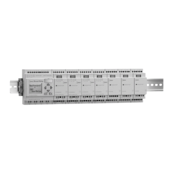
- Page 14 Getting started with IDEC SmartRelay The IDEC SmartRelay structure L1 N I2 I3 I4 I5 I6 I7 I8 L1 N I2 I3 I4 RUN/STOP 1. Power supply 5. Control panel 9. Mechanical coding (not with FL1D-B12...) pins 2. Inputs 6. LCD 10.
- Page 15 Getting started with IDEC SmartRelay L+ M I2 I3 I4 I5 I6 I7 I8 L+ M I2 I3 I4 RUN/STOP 1. Power supply 5. Control panel 9. Mechanical coding (not with FL1D-B12...) pins 2. Inputs 6. LCD 10. Mechanical coding (not with FL1D-B12...)
- Page 16 Getting started with IDEC SmartRelay FL1B-J2B2 L+ M L+ M RUN/STOP INPUT2x(0..10V/0..20mA) M1 U1 M2 U2 1. Power supply 9. Mechanical coding 12. PE terminal, for con- pins necting earth and the shielding of analog 2. Inputs 10. Mechanical coding measuring cables.
- Page 17 Getting started with IDEC SmartRelay How to identify the IDEC SmartRelay The IDEC SmartRelay identifier informs you of various prop- erties. Base module FL1D- B: Base module without display H: Base module with dis- play Number of Inputs and Outputs R: Relay output S: Tr.
- Page 18 Getting started with IDEC SmartRelay Symbols Version with display unit is equipped with 8 inputs and 4 outputs Version without display unit is equipped with 8 inputs and 4 outputs The digital module is equipped with 4 digital inputs and...
- Page 19 Getting started with IDEC SmartRelay Versions The following IDEC SmartRelay versions are available: Symbol Description Supply Inputs Outputs Properties Voltage FL1D-H12RCE 12/24 V DC 8 digital 4 relays (10 A) FL1D-H12SND 24 V DC 4 Transistor no clock 8 digital 24V / 0.3A...
- Page 20 Getting started with IDEC SmartRelay Expansion modules The following expansion modules can be connected to the IDEC SmartRelay: Symbol Description Supply Voltage Inputs Outputs FL1B-M08B2R2 12/24 V DC 4 digital 4 relays (5A) FL1B-M08B1S2 24 V DC 4 digital 4 Transistor 24 V / 0.3 A...
- Page 21 Getting started with IDEC SmartRelay Certification and approvals IDEC SmartRelay is certified to cULus and FM. • cULus Haz. Loc. Underwriters Laboratories Inc. (UL) to - UL 508 (Industrial Control Equipment) - CSA C22.2 No. 142 (Process Control Equipment) - UL 1604 (Hazardous Location)
- Page 22 RUN. In potentially explosive atmospheres, always switch off the power supply to IDEC SmartRelay and its components before you discon- nect any connectors. IDEC SmartRelay is issued with the CE Certificate of Confor- mity.
-
Page 23: Idec Smartrelay Installation And Wiring
Please note the following guidelines for the installation and wiring of your IDEC SmartRelay : • Always ensure that the wiring of your IDEC SmartRelay is compliant with current rules and standards. Also, conform with all national and regional regulations when you install and operate the devices. - Page 24 Access to the housings or cabinets must only be possible by using a key or a tool and only authorized or approved personnel may be allowed access. It is permissible to operate IDEC SmartRelay from its front at any time. Safety of electronic control equipment...
- Page 25 IDEC SmartRelay installation and wiring Reliability Maximum reliability of IDEC SmartRelay devices and com- ponents is achieved by implementing extensive and cost-ef- fective measures during development and manufacture. This includes the following: • Use of high-quality components; • Worst-case design of all circuits;...
- Page 26 IDEC SmartRelay installation and wiring Risks In all cases where the occurrence of failures can result in material damage or injury to persons, special measures must be taken to enhance the safety of the installation - and therefore also of the situation. System-specific and special regulations exist for such applications.
-
Page 27: Modular Idec Smartrelay Setup
IDEC SmartRelay installation and wiring 2.1 Modular IDEC SmartRelay setup 2.1.1 Maximum setup Maximum setup of a IDEC SmartRelay with analog inputs (FL1D-H12RCE/FL1D-B12RCE and FL1D-H12SND) IDEC SmartRelay Base, 4 digital modules and 3 analog modules (example) I1..I6, I7, I8 I9...I12 I13...I16 I17...I20 I21...I24... -
Page 28: Setup With Different Voltage Classes
IDEC SmartRelay installation and wiring controller is an exception: the AI used for the value PV should be on the IDEC SmartRelay Base or an analog input module adjacent to the IDEC SmartRelay Base). We recommend that you position the FL1B-CAS2 on the far right-hand side. -
Page 29: Installing/Removing Idec Smartrelay
IDEC SmartRelay can be snap-mounted to 35 mm DIN rails to EN 50022 or on the wall. IDEC SmartRelay width: • IDEC SmartRelay Base has a width of 72 mm, which cor- responds with 4 subunits. • IDEC SmartRelay expansion modules have a width of 36 mm, which corresponds with 2 subunits. -
Page 30: Din Rail Mounting
IDEC SmartRelay installation and wiring 2.2.1 DIN rail mounting Mounting How to mount an IDEC SmartRelay Base and a digital mod- ule onto a DIN rail: IDEC SmartRelay Base: 1. Hook the IDEC SmartRelay Base module onto the rail 2. then push down the lower end to snap it on. The mount- ing interlock at the rear must engage. - Page 31 IDEC SmartRelay installation and wiring 6. Using a screwdriver, push the interlock to the left. In its end position the slide interlock engages in the IDEC SmartRelay Base. Repeat steps 3 through 6 to mount further expansion mod- ules. Note The expansion interface on the last expansion module must be covered.
- Page 32 IDEC SmartRelay installation and wiring Removal To remove the IDEC SmartRelay: ..if you have installed only one IDEC SmartRelay Base: Part 1. Insert a screwdriver into the eyelet at the bottom of the slide interlock and move the latch downward.
- Page 33 IDEC SmartRelay installation and wiring ..if you have connected at least one expansion module to the IDEC SmartRelay Base: Part 1. Using a screwdriver, push the integrate slide interlock to the right. 2. Slide the expansion module off towards the right.
-
Page 34: Wall-Mounting
Wall-mounting For wall-mounting, first slide the mounting slides on the rear side of the devices towards the outside. You can now wall-mount the IDEC SmartRelay by means of two mounting φ slides and two M4 screws (tightening torque 0.8 to 1.2 Nm). - Page 35 IDEC SmartRelay installation and wiring Drilling template for wall-mounting Before you can wall-mount the IDEC SmartRelay, you need to drill holes using the template shown below. 53.5 +/– 0.2 35.5 +/– 0.2 n x 35.5 +/– 0.2 All dimensions in mm φ...
-
Page 36: Wiring Idec Smartrelay
IDEC SmartRelay installation and wiring 2.3 Wiring IDEC SmartRelay Wire IDEC SmartRelay using a screwdriver with a 3-mm blade. You do not need wire ferrules for the terminals. Permitted conductor cross-sections: • 1 x 2.5 mm • 2 x 1.5 mm for each second terminal chamber Tightening torque: 0.4...0.5 Nm or 3...4 lbs in... -
Page 37: Connecting The Power Supply
M08D2R2) are suitable for a supply voltage of 24 V AC/DC. IDEC SmartRelays (FL1D-H12SND, FL1B-M08B1S2) are suitable for a supply voltage of 24 V DC. IDEC SmartRelays (FL1D-*12RCE, FL1B-M08B2R2) are suitable for a supply voltage of 12 V AC/DC or 24 V AC/DC. - Page 38 20 % above the rated FL1D-H12SND: 2.0 A voltage. Note IDEC SmartRelay is a double-insulated switchgear. You do not need to connect an equipment grounding conductor. Circuit protection with AC voltage To suppress voltage peaks on the power supply lines, you can install a metal oxide varistor (MOV).
-
Page 39: Connecting Idec Smartrelay Inputs
IDEC SmartRelay installation and wiring 2.3.2 Connecting IDEC SmartRelay inputs Requirements At the inputs you connect sensor elements such as: momen- tary switches, switches, light barriers, daylight control switches etc. Sensor characteristics for IDEC SmartRelay FL1D-H12RCE FL1D-H12SND (3),(4),(5) FL1D-B12RCE FL1B-M08B1S2... - Page 40 The level of the quiescent current of some 2-wire proximity switches is high enough to trigger a logical "1" signal at the IDEC SmartRelay input. You should therefore compare the quiescent current of the prox- imity switches with the technical data of inputs Appendix A.
- Page 41 IDEC SmartRelay installation and wiring Remedy To suppress this response, use an X capacitor rated at 100 nF and 2.5 kV. In a destructive situation, this type of capaci- tor safely disconnects. You must choose the voltage level for which the capacitor is rated such that it is not destroyed in...
- Page 42 After a 0 to 1 or 1 to 0 transition, the signal must remain con- stant at the input at least for the duration of one program cy- cle, so that IDEC SmartRelay can detect the new signal sta- tus.
- Page 43 IDEC SmartRelay installation and wiring Connecting a potentiometer to inputs I7 / I8 To allow you to achieve 10 V as the maximum value when you completely turn the potentiometer once, you must con- nect a series resistor on the potentiometer’s input side re- gardless of the input voltage (see figure below).
- Page 44 IDEC SmartRelay installation and wiring Sensor connections To connect sensors to the IDEC SmartRelay : FL1D-H12RCA / FL1D-B12RCA / FL1D-H12RCE / FL1D-B12RCE / FL1D-H12SND The inputs of these devices are not isolated and therefore require a common reference potential (chassis ground ).
- Page 45 IDEC SmartRelay installation and wiring FL1B-J2B2 PE terminal for connecting earth and the shielding of the analog measuring cable 1 Earth 2 Cable shielding 3 DIN rail RUN/STOP I1 M1 U1 I2 M2 U2 Current Reference 0...20mA current Current measurement...
- Page 46 IDEC SmartRelay installation and wiring Input Internal Circuit FL1D-H12RCC / FL1D-B12RCC / FL1B-M08C2R2 Digital AC/DC Input 390kΩ 390kΩ Internal I1~I8 Circuit 100nF 62kΩ When using the AC two-wire sensor I1 to I8 2-wire Sensor 100 to 240 V AC IDEC SmartRelay Manual...
- Page 47 IDEC SmartRelay installation and wiring FL1D-H12RCA / FL1D-B12RCA / FL1B-M08D2R2 Digital AC/DC Input Internal Circuit 4.3kΩ I1~I8 Internal Circuit 100nF 510Ω When using the AC two-wire sensor I1 to I8 2-wire Sensor 240 V AC IDEC SmartRelay Manual ngineering, Inc. ● 230 Ryan Way, South San Francisco, CA 94080-6370 ● General Inquiries: (800) 670-4183 ● www.ste...
- Page 48 IDEC SmartRelay installation and wiring FL1D-H12RCE / FL1D-B12RCE / FL1D-H12SND / FL1B-M08B2R2/ FL1B-M08B1S2 Digital DC Input 3.6kΩ Internal I1~I8 Circuit 100nF 2.2kΩ FL1D-H12RCE / FL1D-B12RCE / FL1D-H12SND / FL1B-J2B2 Analog Input (0-10V) 39kΩ Internal I7, I8 Circuit (U1, U2) 39kΩ...
- Page 49 Fluctuating analog values are due to screening on the connecting wire from the analog valuator device to the analog FL1B-J2B2 IDEC SmartRelay expansion module (encoder wire) that has either been mounted incorrectly or not at all. To avoid fluctuating analog values when using these expansion modules, proceed as follows: •...
-
Page 50: Connecting Outputs
IDEC SmartRelay installation and wiring 2.3.3 Connecting outputs FL1D-H12RCA / FL1D-B12RCA / FL1D-H12RCC / FL1D-B12RCC / FL1D-H12RCE / FL1D-B12RCE These units are equipped with relay outputs. The potential of the relay contacts is isolated from the power supply and the inputs. - Page 51 The load connected to IDEC SmartRelay must have the fol- lowing characteristics: • The maximum switched current is 0.3 A per output. Connecting This is how you connect the load to a IDEC SmartRelay with transistor outputs: load load Load: 24 V DC, 0.3 A max.
- Page 52 IDEC SmartRelay installation and wiring FL1D-K2B2 1 Earth 2 DIN rail L+ M L+ M RUN/STOP OUTPUT 2x(0..10V) V1, V2: 0 - 10 V DC Ω R: min. 5 k 0 10V 0 10V IDEC SmartRelay Manual ngineering, Inc. ● 230 Ryan Way, South San Francisco, CA 94080-6370 ● General Inquiries: (800) 670-4183 ● www.ste...
- Page 53 IDEC SmartRelay installation and wiring Output Internal Circuit FL1D-H12RCA / FL1D-B12RCA / FL1D-H12RCC / FL1D-B12RCC / FL1D-H12RCE/ FL1D-B12RCE / FL1B-M08B2R2 / FL1B-M08C2R2/ FL1B-M08D2R2 Relay Output Internal Circuit +24V Q1~Q4 47kΩ Internal Circuit 27kΩ FL1D-H12SND / FL1B-M08B1S2 Transister Output (Source) Internal Circuit...
-
Page 54: Connecting The As Interface Bus
AS interface power supply and • an AS interface master. IDEC SmartRelay can only be accepted as a slave on the AS interface bus. This means that it is not possible to directly ex- change data between two IDEC SmartRelay devices. Data is always exchanged across the AS interface master. - Page 55 “n” depends on the plug-in position of the expansion module relative to the IDEC SmartRelay Base. It indicates the num- ber of the input or output in IDEC SmartRelay program code. Note Ensure that there is enough space for the inputs/outputs of the AS interface in the IDEC SmartRelay’s address space.
-
Page 56: Putting Into Operation
• Whether this is an IDEC SmartRelay version without dis- play unit (FL1D-B12...) • The status of IDEC SmartRelay at the time of power fail- ure. All possible reaction of IDEC SmartRelay are described on the following page. To ensure that the expansion module on IDEC SmartRelay changes to RUN mode, check the following: •... - Page 57 IDEC SmartRelay installation and wiring Notes for Using Expansion I/O Modules When using 3 or more expansion I/O modules including those of the versions listed below, immediately after power- up, it takes a specific period of time for the base module to accept input signals from the expansion I/O modules.
- Page 58 IDEC SmartRelay installation and wiring Before power off After power on No program No Program Press ESC Press ESC (empty) No program in memory >Program.. Card.. Setup.. (with program) Start With stored program from Mo 09:00 Mo 09:00 2003-01-27 IDEC...
- Page 59 IDEC SmartRelay. The circuit pro- gram in IDEC SmartRelay is overwritten. 3. If there is a circuit program in IDEC SmartRelay or on the memory cartridge (card), IDEC SmartRelay adopts the operational state it had prior to POWER-OFF. Versions...
-
Page 60: Operating States
IDEC SmartRelay installation and wiring 2.4.2 Operating states IDEC SmartRelay Base operating states IDEC SmartRelay Base/Pure knows two operating states: STOP and RUN STOP • The display shows: • Display: Screen mask for 'No Program' monitoring I/Os and messag- (not FL1D-B12...) es (after START in the main •... - Page 61 IDEC SmartRelay installation and wiring IDEC SmartRelay expansion modules, operating states IDEC SmartRelay expansion modules know three operating states: The LED is lit green, red or orange. LED is lit Green (RUN) Red (STOP) Orange The expansion mod- The expansion mod-...
-
Page 62: Programming Idec Smartrelay
WindLGC or memory cartridges (cards) of other IDEC SmartRelay FL1D units. IDEC SmartRelay versions without display can not write data to memory cartridges (cards). See Chapter 6, 7 and Appendix C. - Page 63 ... • can enter directly in IDEC SmartRelay in the third step. It will take you only a few pages of this manual store your first executable circuit program in the IDEC SmartRelay unit.
-
Page 64: Connectors
Analog Inputs Each input is identified by the letter I plus a number. When you look at IDEC SmartRelay from the front, you can see the input terminals at the top. Only the analog modules FL1B- J2B2 has the inputs at the bottom. - Page 65 Programming IDEC SmartRelay Note IDEC SmartRelay can recognize, read and switch the I/O of all ex- pansion modules, regardless of their type. The I/Os are presented in the installation order of the modules. The following I/Os and marker blocks are available for creating your circuit program: I1 to I24, AI1 to AI8, Q1 to Q16, AQ1, AQ2, M1 to M24 and AM1 to AM6.
- Page 66 Programming IDEC SmartRelay IDEC SmartRelay knows the following connectors: Con- IDEC SmartRelay Base / Pure FL1D- K2B2 nectors Inputs FL1D-H12RCC Two groups: I9 ... I24 AI1...AI8 none FL1D-B12RCC I1... I4 and FL1D-H12RCA I5 ... I8 FL1D-B12RCA FL1D-H12RCE I1... I6, I7, I8 I9 ...
-
Page 67: Blocks And Block Numbers
Up/down counter • On-delay • Softkey • ..Chapter 4 gives a full list of the IDEC SmartRelay functions. IDEC SmartRelay Manual ngineering, Inc. ● 230 Ryan Way, South San Francisco, CA 94080-6370 ● General Inquiries: (800) 670-4183 ● www.ste... - Page 68 Programming IDEC SmartRelay Block representation on the IDEC SmartRelay display The figure below shows a typical view of the IDEC SmartRelay display. As you can see, it can show only one block at a time. We have therefore introduced block numbers to help you check the circuit structure.
- Page 69 WindLGC also allows you to assign eight-character names to up to 64 blocks, and to view these on the IDEC SmartRelay display in pa- rameter assignment mode (see Chapter 3.4).
-
Page 70: The Way To Idec Smartrelay, Starting With The Circuit Diagram
Relay K1 picks up when the condition (S1 OR S2) AND S3 is met. Creating this circuit with IDEC SmartRelay In IDEC SmartRelay you create a circuit logic by intercon- necting blocks and connectors: Wiring of the inputs S1 ... S3 Circuit program in IDEC SmartRelay ≥... - Page 71 You program this fourth input and as- sign parameters just like you do with the other three inputs. To create a circuit logic in IDEC SmartRelay, start at the cir- cuit output. The output is the load or relay that is to be switched.
- Page 72 Wiring Connect the switches S1 to S3 to the screw terminals of your IDEC SmartRelay : • S1 to connector I1 of IDEC SmartRelay • S2 to connector I2 of IDEC SmartRelay • S3 to connector I3 of IDEC SmartRelay The output of the AND block controls the relay at output Q1.
-
Page 73: The Four Golden Rules For Operating Idec Smartrelay
During parameter assignment IDEC SmartRelay is in RUN mode, i.e. it continues executing the circuit program (see Chapter 5). To work in programming mode, you need to terminate the circuit program by calling the “Stop”... - Page 74 Press ESC to return to the previous step. Rule 4 Planning • Before you start to create a circuit program, you should either first create design on paper or program IDEC SmartRelay directly using WindLGC. • IDEC SmartRelay can only save complete and faultless circuit programs.
-
Page 75: Overview Of Idec Smartrelay Menus
Programming IDEC SmartRelay 3.5 Overview of IDEC SmartRelay menus Programming mode Main menu Programming menu >Program.. >Edit.. Card.. Clear Prg Setup.. Password Start Transfer menu > Card = IDEC Card SmartRelay CopyProtect Setup menu >Clock Contrast Parameter assignment mode Parameter assignment menu >Stop... -
Page 76: Writing And Starting The Circuit Program
You have connected IDEC SmartRelay to the power supply and switched it on. The display now shows you the message: Switch IDEC SmartRelay to programming mode by pressing ESC. This will take you to the main menu of IDEC SmartRelay: IDEC SmartRelay’s main menu The first character in the first line is the ">"... - Page 77 Note Because we have not yet saved a password for the circuit program in IDEC SmartRelay, you can directly enter editing mode. When you select “Edit” after you have saved a password-protected circuit program, you are prompted to enter a password and to confirm it with OK.
-
Page 78: The First Circuit Program
OR block. Circuit program S1 is connected to the I1 and S2 to the I2 input connector of the OR block. The corresponding layout of the circuit program in IDEC SmartRelay: ≥ IDEC SmartRelay Manual ngineering, Inc. ● 230 Ryan Way, South San Francisco, CA 94080-6370 ● General Inquiries: (800) 670-4183 ● www.ste... -
Page 79: Circuit Program Input
Q1. 3.6.3 Circuit program input Let us now write the circuit program, starting at the output and working towards the input. IDEC SmartRelay initially shows the output: The first IDEC SmartRelay output IDEC SmartRelay Manual ngineering, Inc. ● 230 Ryan Way, South San Francisco, CA 94080-6370 ● General Inquiries: (800) 670-4183 ● www.ste... - Page 80 The cursor no longer appears in the form of an underscore; but instead as a flashing solid square. IDEC SmartRelay of- fers you various options here. Select GF (basic functions) by pressing the ▼ key until GF appears, and confirm with OK.
- Page 81 Programming IDEC SmartRelay Now press ▼ or ▲ until the OR block appears on the display: The solid square cursor is still posi- ≥ 1 tioned on the block. Press OK to confirm your entries and exit the dialog. Your complete circuit...
- Page 82 The cursor jumps to the next input of the OR block. Your complete circuit program The display now shows: in IDEC SmartRelay up to now: ≥ 1 ≥ Now you connect input I2 to the input of the OR block. You already know how to do this: 1.
- Page 83 I2 is now connected to the input of the OR block: Your circuit program layout in The display now shows: IDEC SmartRelay up to now ≥ 1 ≥ We do not need the last two inputs of the OR block for this circuit program.
- Page 84 Programming IDEC SmartRelay Note You can invert individual inputs of the basic and special functions, i.e. if an input carries a logical “1” signal, the circuit program will out- put a logical “0”. On the other hand, a logical “0” is inverted into a logical “1”...
-
Page 85: Assigning A Circuit Program Name
Programming IDEC SmartRelay Note IDEC SmartRelay has now saved your circuit program to nonvola- tile memory. The circuit program remains in the IDEC SmartRelay memory until you explicitly delete it. You can save the actual values of special functions in the case of a power outage assuming that these functions support the “Reten-... -
Page 86: Password
To assign a password A password may have a maximum length of 10 characters, and consists only of uppercase letters (A to Z). On IDEC SmartRelay, the password can be assigned, edited or deac- tivated only in the “Password” menu. - Page 87 Programming IDEC SmartRelay Press ▲ once to select “Z” Press ▲ twice to select “Y”, etc. Let us assign the password “AA” to our first circuit program. The display now shows: Old: No Password New: This procedure is the same as for entering the name of the circuit program.
- Page 88 Programming IDEC SmartRelay Note You can cancel the input of a new password with ESC. In this case, IDEC SmartRelay returns to the programming menu without saving the password. You can also set your password using WindLGC. You can not edit a password-protected circuit program on IDEC SmartRelay or up- load it to WindLGC unless you enter the correct password.
- Page 89 Programming IDEC SmartRelay The display now shows: Old: New: 6. To confirm your new password:Press OK Your new password “ZZ” is now set, and you are returned to the programming menu. Deactivating the Password Let us assume you want to deactivate the password for whichever reason.
- Page 90 Password: Wrong Password! When the user inputs the wrong password and confirms the input with OK, IDEC SmartRelay does not open editing mode, but returns to the programming menu. This repeats it- self over and again until you input the correct password.
-
Page 91: Switching Idec Smartrelay To Run Mode
Programming IDEC SmartRelay 3.6.6 Switching IDEC SmartRelay to RUN mode In the main menu, select RUN to start IDEC SmartRelay. 1. To return to the main menu: Press ESC Press ▲ or ▼ 2. Move the '>' cursor to 'Start': 3. - Page 92 Programming IDEC SmartRelay 7: 00000 Analog inputs AI7 to AI8 8: 00000 Press 1: 00000 Analog outputs AQ1 to AQ2 2: 01000 Press Markers M1 to M9 0.. 123456789 Markers M10 to M19 1..0123456789 2..01234 Markers M20 to M24 Press...
- Page 93 What is meant by: "IDEC SmartRelay is in RUN"? In RUN mode, IDEC SmartRelay executes the circuit pro- gram. To do so, IDEC SmartRelay first reads the status at the inputs, determines the status of the outputs by means of the user program, and switches these on or off according to your settings.
-
Page 94: Second Circuit Program
S1 and S2 switch a relay, which is to be used to switch on the load E1, and to switch off the load with a delay of 12 minutes. This is the circuit program layout in IDEC SmartRelay: ≥ This is the new block You can see the OR block and the output relay Q1 we have already used in the first circuit program. - Page 95 Editing the circuit program Switch IDEC SmartRelay to programming mode. As a reminder: 1. Switch the IDEC SmartRelay to programming mode (in RUN: Press ESC to enter the parameter assignment mode. Select the ‘Stop’ command, confirm with OK, then move the ‘>’ cursor to ‘Yes’, and once again confirm with OK).
- Page 96 The block of the first special function is shown: When you select a special or basic function block, IDEC SmartRelay shows you the rele- vant function block. The solid square cursor is positioned on the block. Press ▼ or ▲ to select the required block.
- Page 97 1. Move the cursor to Par, if it not already at this position: Press ▲ or ▼ 2. Switch to editing mode: Press OK IDEC SmartRelay shows the parameters in the parameter assignment window: “+” means: The parameter is shown and can be modified...
- Page 98 Programming IDEC SmartRelay Setting the time Set the time T = 12:00 minutes: 1. Move the cursor to the first digit: Press Press ▲ or ▼ 2. Select the digit '1': 3. Shift the cursor to the second digit: Press Press ▲...
- Page 99 “/”) settings are only shown in the displays where these can ac- tually be changed. Verification of the circuit program This program branch for Q1 is now completed. IDEC SmartRelay shows you the output Q1. You can once again view the circuit program on the display. Use the keys to browse the circuit program, i.e.
- Page 100 Press ▲ or ▼ 3. To move the '>' cursor to 'Start': 4. To confirm 'Start': Press OK IDEC SmartRelay is back in RUN mode: You can press to scroll the pag- es and to monitor the I/O states. Mo 09:30...
-
Page 101: Deleting A Block
Let us assume you want to delete the block B2 from your cir- cuit program and connect B1 directly to Q1. Proceed as follows: 1. Switch the IDEC SmartRelay to programming mode (as a reminder, refer to page 63). Press ▲ or ▼... -
Page 102: Deleting Block Groups
Let us assume you want to delete the blocks B1 and B2 from the following circuit program (corresponds with the circuit program in Chapter 3.6.7). Proceed as follows: 1. Switch IDEC SmartRelay to programming mode (as a reminder, refer to page 63). Press ▲ or ▼ 2. To select 'Edit': 3. -
Page 103: Correcting Programming Errors
You can select either ‘Last’ value (i.e. analog output values are held at their last value) or ‘Defined’ value (i.e. analog output values are set to specific values). When IDEC SmartRelay changes from RUN mode to STOP mode, the IDEC SmartRelay Manual... - Page 104 Programming IDEC SmartRelay values of the analog outputs change as well, depending on the setting. Press ▲ or ▼. 5. Select the desired output setting: 6. To confirm your entry: Press OK Defining a specific analog output value You want to output a specific analog value at the two analog outputs.
-
Page 105: Deleting The Circuit Program
Programming IDEC SmartRelay 3.6.12 Deleting the circuit program To delete a circuit program: 1. Switch the IDEC SmartRelay to programming mode IDEC SmartRelay opens the >Program.. main menu Card.. Setup.. Start 2. On the main menu, press ▲ or ▼ to move the ‘>’ cursor to ‘Program’. -
Page 106: Summertime/Wintertime Conversion
“Setup” menu com- mand. To enable/disable automatic S/W Time conversion in program- ming mode: 1. Switch IDEC SmartRelay to programming mode. 2. You are now in the main menu and want to select the Press ▲ or ▼ ‘Setup’ menu command: 3. - Page 107 Programming IDEC SmartRelay IDEC SmartRelay shows the following display: >On S/W Time: The current setting of automatic S/W Time conversion is shown in the bottom row. The default setting is ‘Off’: dis- abled. To enable/disable automatic S/W Time conversion in parameter...
- Page 108 Programming IDEC SmartRelay • ‘AUS’ represents the start and end of Australian summer- time. • ‘AUS-TAS’ represents the start and end of Australian/ Tasmanian summertime. • ‘NZ’ represents the start and end of New Zealand sum- mertime. • . . : Here you can enter any month, day and time zone dif- ference.
- Page 109 IDEC SmartRelay shows the following display: >On S/W Time: On EU IDEC SmartRelay indicates that European S/W Time con- version is enabled. User-defined parameters If none of the parameters/conversions apply to your country, you can customize these under menu item ‘. .’. To do so: 1.
- Page 110 Note Summertime/wintertime conversion only functions when IDEC SmartRelay is operating (in RUN or STOP status). It does not func- tion when IDEC SmartRelay is in buffered operation (see Chapter 4.3.3). IDEC SmartRelay Manual ngineering, Inc. ● 230 Ryan Way, South San Francisco, CA 94080-6370 ● General Inquiries: (800) 670-4183 ● www.ste...
-
Page 111: Synchronization
(“Clock” menu item). 1. Switch the IDEC SmartRelay to programming mode. 2. You are now in the main menu, and want to select Press ▲ or ▼... -
Page 112: Memory Space And Circuit Dimensions
Programming IDEC SmartRelay 3.7 Memory space and circuit dimensions The size of a circuit program in IDEC SmartRelay is limited by the memory space (memory used by the blocks). Memory areas • Program memory: IDEC SmartRelay allows only a limited number of blocks in your circuit program. - Page 113 With an input (I1) connected to a Trg connector of an On-delay FB as shown in Fig.1, if I1 is ON and the IDEC SmartRelay power is turned off and on, the timer current value of the On-delay FB is sometimes reset as shown in Fig.2.
- Page 114 Programming IDEC SmartRelay Resources available in IDEC SmartRelay A circuit program in IDEC SmartRelay can occupy the follow- ing maximum resources: Bytes Blocks 2000 IDEC SmartRelay monitors memory utilization, and offers only those functions from the lists for which it can actually provide sufficient memory space.
- Page 115 The system indicates that there is insufficient memory space by not allowing you to add a further block to your circuit pro- gram. IDEC SmartRelay offers you only the blocks for which it can provide sufficient memory space. If IDEC SmartRelay...
- Page 116 Still available in IDEC SmartRelay 1924 (1): Configured with retentivity. This means that this circuit program fits in IDEC SmartRelay. IDEC SmartRelay Manual ngineering, Inc. ● 230 Ryan Way, South San Francisco, CA 94080-6370 ● General Inquiries: (800) 670-4183 ● www.ste...
- Page 117 Programming IDEC SmartRelay Indication of available memory space IDEC SmartRelay shows you the amount of free memory space. Proceed as follows: 1. Switch the IDEC SmartRelay to programming mode (as a reminder, refer to page 63). Press ▲ or ▼...
-
Page 118: Idec Smartrelay Functions
All lists show the elements available in IDEC SmartRelay. Usually, this includes all connectors, basic functions and special functions the IDEC SmartRelay knows. This includes all the blocks you have created in IDEC SmartRelay by the time you call the ↓BN list. If not all is shown IDEC SmartRelay does not show all elements if: •... -
Page 119: Constants And Connectors - Co
Digital inputs are identified with an I. The number of the dig- ital inputs (I1, I2, ...) corresponds to the number of the input connectors of the IDEC SmartRelay Base and of the con- nected digital modules, in the order of their installation. See the following figure below. - Page 120 Digital outputs are identified by the character Q. The output numbers (Q1, Q2, ... Q16) correspond with the numbers of the output connectors at the IDEC SmartRelay Base and with those of the expansion modules, in their order of instal- lation.
- Page 121 This value does not change within the same pro- gram cycle. Shift register bits IDEC SmartRelay provides the shift register bits S1 to S8, which are assigned the read-only attribute in the circuit pro- gram. The content of shift register bits can only be modified by means of the “Shift register”...
-
Page 122: Basic Functions List - Gf
IDEC SmartRelay functions 4.2 Basic functions list - GF Basic functions represent simple logical elements of Bool- ean algebra. You can invert the inputs of individual basic functions, i.e. the circuit program inverts a logical “1” at a relevant input to a logical “0”;... - Page 123 IDEC SmartRelay functions View in the circuit View in IDEC Name of the basic diagram SmartRelay function (see page 118) Parallel circuit with normally open con- tact (not OR) Series circuit with (see page 119) normally closed con- tact (exclusive OR)
-
Page 124: And
IDEC SmartRelay functions 4.2.1 Circuit diagram of a series circuit with Symbol in IDEC SmartRelay: several normally open contacts: The output of the AND is only 1 if all inputs are 1, i.e. all con- tacts are closed. At an unused block input (x): x = 1. -
Page 125: And With Edge Detection
IDEC SmartRelay functions 4.2.2 AND with Edge Detection Symbol in IDEC SmartRelay: The output of an edge triggered AND is only 1 if all inputs are 1 and if at least one input was low in the previous cycle. At an unused block input (x): x = 1. -
Page 126: Nand (Not And)
NAND (not AND) Parallel circuit with multiple normally closed contacts in the circuit diagram: Symbol in IDEC SmartRelay: The output of the NAND is only 0 if the status at all inputs is 1, i.e. the contacts are closed. At an unused block input (x): x = 1. -
Page 127: Nand With Edge Detection
IDEC SmartRelay functions 4.2.4 NAND with Edge Detection Symbol in IDEC SmartRelay: The output status of the NAND with Edge Detection is only 1 if at least one input is 0 and if all inputs were 1 in the previ- ous cycle. - Page 128 Circuit diagram of a parallel circuit with several normally open contacts: Symbol in IDEC SmartRelay: The output status of the OR element is only 1 if at least one input is 1, i.e. at least one of the contacts is closed.
-
Page 129: Nor (Not Or)
Circuit diagram of a series circuit with several normally closed contacts: Symbol in IDEC SmartRelay: The output status of the NOR is only 1 if all inputs are 0, i.e. if switched off. The NOR output is set to 0 when one of the inputs is switched on (logical 1 status). -
Page 130: Xor (Exclusive Or)
The output status is 1 if the input is 0. The NOT block inverts the input status. Advantage of the NOT block, for example: The IDEC SmartRelay does not require normally closed contacts. You simply use a normally open contact and the NOT block to convert these into a normally closed contact. -
Page 131: Basics On Special Functions
IDEC SmartRelay functions 4.3 Basics on special functions Because of their different input designation, you can see right away that there is a difference between the special functions and basic functions. SFs contain timer functions, retentive functions and various parameter assignment op- tions, which allow you to adapt the circuit program to suit your own requirements. -
Page 132: Designation Of The Inputs
Logical inputs Here, you will find the description of the connectors you can use to create a logical link to other blocks or to the inputs of the IDEC SmartRelay unit. • S (Set): A signal at input S sets the output to logical “1”. -
Page 133: Time Response
Accuracy of T Because of slight tolerances in the characteristics of electronic components, the set time T may deviate. IDEC SmartRelay has a maximum tolerance of ± 0.02%. When 0.02% of the time T is smaller than 0.02 seconds, the maximum deviation is 0.02 seconds. -
Page 134: Backup Of The Real-Time Clock
25°C, the typical backup time is 80 hours. If there is a power outage of an IDEC SmartRelay for more than 80 hours, the internal clock responds, as shown below: On restarting, the clock is set to "Sunday 00:00 1 January". The time is stopped and flashes. -
Page 135: Calculating The Gain And Offset Of Analog Values
10 V is shown as internal value 1000. Because you can not always process the range of values from 0 to 1000 as predetermined by IDEC SmartRelay, you can multiply the digital values by a gain factor and then shift the zero of the range of values (offset). - Page 136 Example 1: The available thermocouples have the following technical data: -30 to +70°C, 0 to 10 V DC (i.e. 0 to 1000 in IDEC SmartRelay). Actual value = (internal value • gain) + offset, thus = (0 •...
- Page 137 IDEC SmartRelay functions Example of analog values Process Voltage Internal Gain Offset Value variable value shown (Ax) -30° C 0° C +70° C 1000 1000 mbar 1000 1000 3700 mbar 6.75 1000 3700 5000 mbar 1000 1000 5000 0.01 0.01 1000 0.01...
-
Page 138: Special Functions List - Sf
IDEC SmartRelay functions 4.4 Special functions list - SF When you create your circuit program in IDEC SmartRelay, you find the special function blocks in the SF list. You can invert the inputs of SFs individually, i.e. the circuit program converts a logical “1” at the input into a logical “0”;... - Page 139 IDEC SmartRelay functions View Name of the in IDEC SmartRelay special function Edge-triggered interval time- delay relay (see page 144) Asynchronous pulse generator (see page 147) Random generator (see page 149) Stairwell Light Switch (see page 151) Dual-function switch (see page 154)
- Page 140 IDEC SmartRelay functions View Name of the in IDEC SmartRelay special function Counter Up/down counter (see page 165) Operating hours counter (see page 169) Frequency trigger (see page 174) Analog Analog trigger (see page 177) Analog differential trigger (see page 180)
- Page 141 IDEC SmartRelay functions View Name of the in IDEC SmartRelay special function Analog multiplexer (see page 213 Analog Ramp Control (see page 217 PI controller (see page 222 Miscellaneous Latching relay (see page 195) Current impulse relay (see page 196)
-
Page 142: On-Delay
IDEC SmartRelay functions 4.4.1 On-delay Short description The output is only set after a configurable on-delay time has expired. Symbol in IDEC Wiring Description SmartRelay Input Trg You start the on-delay with a negative edge (1 to 0 transition) at input Trg (Trigger). - Page 143 IDEC SmartRelay functions Valid ranges of the timebase, if T = parameter Timebase max. value min. resolution Accuracy s (seconds) 99:99 10 ms + 10 ms m (minutes) 99:59 + 1 s h (hours) 99:59 1 min + 1 min...
- Page 144 IDEC SmartRelay functions Parameter preset = Actual value of an already programmed func- tion How to include the actual value of an already programmed function: 1. Press to move the cursor to the equal sign of param- eter T. Press...
- Page 145 The time T is triggered with a 0 to 1 transition at input Trg is the current IDEC SmartRelay time). If the status of input Trg is 1 at least for the duration of the configured time T, the output is set to 1 on expiration of this time (the output follows the input with on-delay).
-
Page 146: Off-Delay
IDEC SmartRelay functions 4.4.2 Off-delay Short description When an on-delay is set, the output is reset when the config- ured time has expired. Symbol in Wiring Description IDEC SmartRelay Input Trg You start the off-delay time with a negative edge (1 to 0... - Page 147 Output Q is set to hi immediately when the input Trg changes to hi. The actual time T in IDEC SmartRelay is retriggered at the 1 to 0 transition of Trg. The output remains set. Output Q is reset to 0 with off-delay when T...
-
Page 148: On-/Off-Delay
IDEC SmartRelay functions 4.4.3 On-/Off-delay Short description The on-/off-delay function sets the output after the set on-de- lay time has expired, and resets it upon expiration of the off-delay time. Symbol in Wiring Description IDEC SmartRelay Input Trg A positive edge (0 to 1 transi-... - Page 149 IDEC SmartRelay functions Parameters T and T Note the preset values for the parameters T and T Chapter 4.3.2. Timing diagram The bold section of the timing dia- gram is also shown in the on/ off-delay symbol. expires expires Functional description The time T is triggered with a 0 to 1 transition at input Trg.
-
Page 150: Retentive On-Delay
IDEC SmartRelay functions 4.4.4 Retentive on-delay Short description A one-shot at the input triggers a configurable on-delay time. The output is set when this time has expired. Symbol in Wiring Description IDEC Smart Relay Input Trg A signal at input Trg (Trigger) triggers the on-delay time. - Page 151 IDEC SmartRelay functions Timing diagram expires The bold section of the timing diagram is also shown in the symbol of the retentive on-delay. Functional description The 0 to 1 signal transition at input Trg triggers the current time T . Output Q is set when T = T.
-
Page 152: Interval Time-Delay Relay / Pulse Output
IDEC SmartRelay functions 4.4.5 Interval time-delay relay / Pulse output Short description An input pulse generates a signal with a configurable period at the output. Symbol in Wiring Description IDEC SmartRelay Input Trg A signal at input Trg (Trigger) triggers the time for the Inter- val time-delay relay function. - Page 153 IDEC SmartRelay functions Functional description A 0 to 1 transition at input Trg sets the output, and triggers a time T during which the output remains set. Output Q is reset to lo (pulse output) when T reaches the value preset at T (T = T).
-
Page 154: Edge-Triggered Interval Time-Delay Relay
IDEC SmartRelay functions 4.4.6 Edge-triggered interval time-delay relay Short description An input pulse generates a preset number of output pulses with a defined pulse/pause ratio (retriggerable), after a con- figured delay time has expired. Symbol in Wiring Description IDEC SmartRelay... - Page 155 IDEC SmartRelay functions Timing diagram B Timing diagram for the sample configuration Functional description A 0 to 1 transition at input Trg triggers the time T (Time Low). After the time T has expired, output Q is set for the duration of T (Time High).
-
Page 156: Idec Smartrelay Manual
IDEC SmartRelay functions View in parameter assignment mode (example): TL =02:00s TH =03:00s Ta =01:15s Current pulse width T or T IDEC SmartRelay Manual ngineering, Inc. ● 230 Ryan Way, South San Francisco, CA 94080-6370 ● General Inquiries: (800) 670-4183 ● www.ste... -
Page 157: Asynchronous Pulse Generator
IDEC SmartRelay functions 4.4.7 Asynchronous pulse generator Short description The output pulse shape can be modified by reconfiguring the pulse/pause ratio. Symbol in Wiring Description IDEC SmartRelay Input En You can use input EN to set and reset the asynchronous pulse generator. - Page 158 IDEC SmartRelay functions Functional description You can configure the pulse/interpulse width at the T (Time High) and T (Time Low) parameters. Input Inv can be used to invert the output signal, provided the block is enabled with a signal at input EN.
-
Page 159: Random Generator
IDEC SmartRelay functions 4.4.8 Random generator Short description The output of the random generator is set or reset within a configured time. Symbol in Wiring Description IDEC SmartRelay Input En A positive edge ( 0 to 1 tran- sition) at input En (Enable) triggers the on-delay time of the random generator. - Page 160 IDEC SmartRelay functions Timing diagram The bold section of the timing diagram also appears in the symbol of the random genera- tor. T is busy Functional description The 0 to 1 transition at input En triggers a random on-delay time between 0 s and T .
-
Page 161: Stairwell Light Switch
IDEC SmartRelay functions 4.4.9 Stairwell Light Switch Short description An input edge triggers a configurable and retriggerable time. The output is reset after this time has expired. A warning sig- nal can be output before this time has expired to warn of the impending shutdown. - Page 162 IDEC SmartRelay functions Functional description A 0 to 1 signal transition at input Trg sets output Q. The next 1 to 0 transition at Trg retriggers the current time T , and out- put Q remains set. Output Q is reset when T = T.
- Page 163 IDEC SmartRelay functions View in parameter assignment mode (example): =60:00s Ta =06:00s Current value of T IDEC SmartRelay Manual ngineering, Inc. ● 230 Ryan Way, South San Francisco, CA 94080-6370 ● General Inquiries: (800) 670-4183 ● www.ste...
-
Page 164: Dual-Function Switch
IDEC SmartRelay functions 4.4.10 Dual-function switch Short description Switch with two different functions: • Pulse switch with off-delay • Switch (permanent lighting) Symbol in Wiring Description IDEC SmartRelay Input Trg A signal at input Trg (Trigger) sets output Q (permanent light) or resets it with off-delay. - Page 165 IDEC SmartRelay functions Timing diagram is busy Functional description A 0 to 1 transition at input Trg sets output Q. If output Q = 0, and input Trg is set hi at least for the duration of T , the permanent lighting function is enabled and output Q is set accordingly.
- Page 166 IDEC SmartRelay functions Press Start of the off-warning period T! =30:00s (T - T Off-warning time T!L =20:00s View in parameter assignment mode (example): =60:00s TL =10:00s Current value of the time T or T Ta =06:00s IDEC SmartRelay Manual...
-
Page 167: Seven-Day Time Switch
IDEC SmartRelay functions 4.4.11 Seven-day time switch Short description The output is controlled by means of a configurable on/off date. The function supports any combination of weekdays. You select the active weekdays by hiding the inactive days. Note Because the FL1D-H12SND does not have a real-time clock, the Seven-day time switch function is not available for this version. - Page 168 IDEC SmartRelay functions Functional description Each Seven-day time switch has three cams you can use to configure a time hysteresis. You specify the on- and off-times at the Cam parameters. The Seven-day time switch sets the output at a certain on-time, if this is not already set.
- Page 169 To set the on-/off-times: 1. Move the cursor to one of the Cam parameters of the timer (e.g. No1). 2. Press OK. IDEC SmartRelay opens the Cam parameter assignment screen form. The cursor is positioned on the weekday. 3. Press ▲ and ▼ to select one or several weekdays.
- Page 170 IDEC SmartRelay functions Seven-day time switch: Example The output of the Seven-day time switch is to be set daily from 05:30 h to 07:40 h. The output should also be set every Tuesday from 03:10 h to 04:15 h, and at the weekends from 16:30 h to 23:10 h.
- Page 171 IDEC SmartRelay functions Cam3 Cam No3 must set the output of the Seven-day time switch switch every Saturday and Sunday from 16:30 h to 23:10 h. D=----SS On =16:30 Off=23:10 Result Monday Wednesday Friday Sunday Tuesday Saturday Thursday IDEC SmartRelay Manual...
-
Page 172: Twelve-Month Time Switch
IDEC SmartRelay functions 4.4.12 Twelve-month time switch Short description The output is controlled by means of a configurable on/off date. Note Because FL1D-H12SND does not have a real-time clock, the Twelve-month time switch is not available for this version. Symbol in... - Page 173 IDEC SmartRelay functions Sample configuration The output of a IDEC SmartRelay is to be set annually on March 1, reset on April 4, set again on July 7, and reset again on November 19. You need to configure two Twelve-month time switches with corresponding on-times.
- Page 174 IDEC SmartRelay functions Further examples **-DD On =**-01 On-time is the first, Off=**-02 and off-time the second day each month. **-DD On =**-10 Each month, from the 10th through to the Off=**-20 20th **-DD On =**-25 In the next month,...
-
Page 175: Up/Down Counter
IDEC SmartRelay functions 4.4.13 Up/down counter Short description An input pulse increments or decrements an internal value, depending on the parameter setting. The output is set or re- set when a configured threshold is reached. The direction of count can be changed with a signal at input Dir. - Page 176 IDEC SmartRelay functions Symbol in Wiring Description IDEC SmartRelay Parameter On: On threshold Range of values: 0...999999 Off: Off threshold Range of values: 0...999999 Retentivity for internal counter value Cnt: / = No retentivity R = The status is retentive.
- Page 177 IDEC SmartRelay functions Calculation rule • If the On threshold ≥ Off threshold, then: Q = 1, if Cnt ≥ On Q = 0, if Cnt < Off. If the On threshold < Off threshold, then Q = 1, if On ≤ Cnt •...
- Page 178 IDEC SmartRelay functions View in programming mode (example): On =001234 On =123456 Off=000000 Off B021 If the referenced block (B6, in the example) returns a value that lies out of the valid range, the value is rounded to the next valid value.
-
Page 179: Operating Hours Counter
R resets output Q and sets a configured value MI at the counter for the duration of the time-to-go (MN). Input En En is the monitoring input. IDEC SmartRelay scans the on-time of this input. Input Ral A positive edge at input Ral (Re-... - Page 180 IDEC SmartRelay functions Symbol in Wiring Description IDEC SmartRelay Parameter Maintenance interval to be preset in hour units Range of values: 0000...9999 h OT: The accumulated total operating time; you can specify an offset Range of values: 00000...99999 h Q → 0: •...
- Page 181 OT = Total time expired since the last hi signal at input Ral Functional description The Operating hours counter monitors input En. When En = 1, IDEC SmartRelay computes the time expired and the time-to-go MN. IDEC SmartRelay shows these times in pa- rameter assignment mode. Output Q is set when the time-to-go MN = 0.
- Page 182 IDEC SmartRelay functions Viewing the MI, MN and OT values • IDEC SmartRelay Base with display unit: You can open the parameter assignment mode when the system is in RUN to view the actual values of MI, MN and OT.
- Page 183 IDEC SmartRelay functions View in parameter assignment mode: MI = 0100h Time interval MN = 0017h Time-to-go Total operating hours OT =00083h IDEC SmartRelay Manual ngineering, Inc. ● 230 Ryan Way, South San Francisco, CA 94080-6370 ● General Inquiries: (800) 670-4183 ● www.ste...
-
Page 184: Frequency Trigger
IDEC SmartRelay functions 4.4.15 Frequency trigger Short description The output is set and reset with two configurable frequency triggers. Symbol in Wiring Description IDEC SmartRelay Input Fre The function counts the 0 to 1 transitions at input Fre. 1 to 0 transitions are not counted. - Page 185 IDEC SmartRelay functions Timing diagram On = 9 Off = 5 = 10 = Input frequency Functional description The Frequency trigger measures the signals at input Fre. The pulses are recorded across a configurable time G_T. Output Q is set and reset in accordance with the set thresh- olds.
- Page 186 G_T=01:00s (example) Note The “seconds” timebase is here set as permanent default. When you preset a time G_T of 1 s, the IDEC SmartRelay returns the current frequency in parameter f in Hz. View in parameter assignment mode (example): On =0009...
-
Page 187: Analog Trigger
IDEC SmartRelay functions 4.4.16 Analog trigger Short description The output is set and reset at two configurable thresholds. Symbol in Wiring Description IDEC SmartRelay Input Ax You apply the analog signal to be analyzed at input Ax. Use the analog inputs AI1...AI8... - Page 188 IDEC SmartRelay functions Gain and offset parameters Please note the information on gain and offset parameters in Chapter 4.3.6. Parameter p (number of decimals) Does not apply to the display of On, Off and Ax values in a message text.
- Page 189 IDEC SmartRelay functions Preset of the Par parameter The gain and offset parameters are used to adapt the sen- sors to the relevant application. View in programming mode (example): Parameter protection mode On threshold On =+04000 Off threshold Off =+02000...
-
Page 190: Analog Differential Trigger
IDEC SmartRelay functions 4.4.17 Analog differential trigger Short description The output is set and reset depending on a configurable threshold and a differential value. Symbol in Wiring Description IDEC SmartRelay Input Ax You apply the analog signal to be analyzed at input Ax. - Page 191 IDEC SmartRelay functions Gain and offset parameters Please note the information on gain and offset parameters in Chapter 4.3.6. Parameter p (number of decimals) Does not apply to the display of On, Off and Ax values in a message text.
- Page 192 IDEC SmartRelay functions Calculation rule ∆ • When you set a negative differential value , the On threshold ≥ Off threshold, and: Q = 1, if the actual value Ax > On Q = 0, if the actual value Ax ≤ Off.
- Page 193 IDEC SmartRelay functions Press ▼ Off threshold Off =+02000 IDEC SmartRelay Manual ngineering, Inc. ● 230 Ryan Way, South San Francisco, CA 94080-6370 ● General Inquiries: (800) 670-4183 ● www.ste...
-
Page 194: Analog Comparator
IDEC SmartRelay functions 4.4.18 Analog comparator Short description The output is set and reset, depending on the difference Ax - Ay and on two configurable thresholds. Symbol in Wiring Description IDEC SmartRelay Inputs Ax and You apply the analog signals... - Page 195 IDEC SmartRelay functions Gain and offset parameters For more information on the gain and offset parameters, re- fer to Chapter 4.3.6. Parameter p (number of decimals) ∆ Does not apply to Ax, Ay, On, Off and values displayed in a message text.
- Page 196 IDEC SmartRelay functions Calculation rule If the On threshold ≥ Off threshold, then: • Q = 1, if: (actual value Ax - actual value Ay) > On Q = 0, if: (actual value Ax - actual value Ay) ≤ Off.
- Page 197 IDEC SmartRelay functions The thermocouples available have the following technical data: -30 to +70°C, 0 to 10 VDC. Application Internal mapping -30 to +70 °C = 0 to 10 V DC 0 to 1000 0 °C → Offset = -30...
- Page 198 IDEC SmartRelay functions Press ▼ Ax =+00010 Temperature values Ay =-00020 ∆ Q = 1 (differential value > On) =+00030 View in the message text (example): Ax =+00010 Ay =-00020 Reducing the input response of the analog comparator You can selectively delay the output of an analog compara- tor by means of the “On-delay”...
-
Page 199: Analog Value Monitoring
IDEC SmartRelay functions 4.4.19 Analog value monitoring Short description This special function saves the process variable of an analog input to memory, and sets the output when the output vari- able exceeds or drops below this stored value plus a config- urable offset. - Page 200 IDEC SmartRelay functions Gain and offset parameters For more information on gain and offset parameters, refer to Chapter 4.3.6. Parameter p (number of decimals) ∆ Applies only to the Aen, Ax and values displayed in a mes- sage text. Timing diagram Aen + ∆...
- Page 201 IDEC SmartRelay functions Preset of the Par parameter The gain and offset parameters are used to adapt the used sensors to the respective application. View in programming mode: Parameter protection mode ∆ Differential value for the on/ = 00000 off threshold Press =00.00...
-
Page 202: Analog Amplifier
IDEC SmartRelay functions 4.4.20 Analog amplifier Short description This special function amplifies the value of an analog input and outputs the result at an analog output. Symbol in Wiring Description IDEC SmartRelay Input Ax You apply the analog signal to be amplified at input Ax. - Page 203 IDEC SmartRelay functions Functional description The function fetches the analog signal of input Ax. This value is multiplied by the value of the A (gain) parame- ter, and parameter B (offset) is then added to the product, i.e. (Ax • gain) + offset = actual value Ax.
- Page 204 IDEC SmartRelay functions View in parameter assignment mode (example): 02.50 = – 00300 = – 00250 IDEC SmartRelay Manual ngineering, Inc. ● 230 Ryan Way, South San Francisco, CA 94080-6370 ● General Inquiries: (800) 670-4183 ● www.ste...
-
Page 205: Latching Relay
IDEC SmartRelay functions 4.4.21 Latching relay Short description Input S sets output Q, input R resets output Q again. Symbol in Wiring Description IDEC SmartRelay Input S You set output Q with a sig- nal at input S. Input R You reset output Q with a signal at input R. -
Page 206: Current Impulse Relay
IDEC SmartRelay functions 4.4.22 Current impulse relay Short description A short pulse at the input sets and resets the output. Symbol in Wiring Description IDEC SmartRelay Input Trg You set and reset output Q with a signal at input Trg (Trigger). - Page 207 IDEC SmartRelay functions Functional description Output Q changes its status, i.e. the output is set or reset, with each 0 to 1 transition at input Trg and if the inputs S and R = 0. The signal at input Trg does not influence the special func- tion when S or R = 1.
- Page 208 IDEC SmartRelay functions Depending on your configuration, either input R takes priority over input S (i.e. input S is not effective when R = 1), or vice versa (i.e. input R is not effective when S = 1). After a power failure, the current impulse relay and output Q are reset if you have not enabled retentivity.
-
Page 209: Message Texts
IDEC SmartRelay functions 4.4.23 Message texts Short description View of a configured message text in RUN mode. Symbol in Wiring Description IDEC SmartRelay Input En A 0 to 1 transition at input En (Enable) starts the output of the message text. - Page 210 IDEC SmartRelay functions Restriction A maximum of 10 message text functions are available. Functional description With the 0 to 1 transition of the signal at input En and when the system is in RUN, the message text you have configured (process variable, text, time-of-day, date) is output to the dis- play.
- Page 211 IDEC SmartRelay functions Example This is how two message texts could be shown: Display field of the IDEC SmartRelay in RUN mode Motor 5 STOP AT Example: Message text with priority 30 10:12 !!Action!! Press Motor 2 3000 Example: Message text with priority 10...
- Page 212 IDEC SmartRelay functions IDEC SmartRelay shows: Priority Priority 1 Quit=On Status of acknowledgment “On” 4. Confirm the entries with Visible parameters or process variables The following parameter or process variables can be dis- played in a message text: Special function...
- Page 213 IDEC SmartRelay functions Special function Parameter or process vari- able visible in a message text ∆, A, B, Ax, Aen Analog value monitoring Analog amplifier A, B, Ax Analog multiplexer V1, V2, V3, V4, AQ Analog Ramp Control L1, L2, MaxL, StSp, Rate, A, B,...
- Page 214 IDEC SmartRelay functions Preset of the Par parameter To configure the message text (programming mode): Parameter assignment screen form for Par Press to select a line for the message text. Press ▲ or ▼ to select the relevant type of message text (Text, Par, Time...).
- Page 215 IDEC SmartRelay functions Press OK to open the editing mode: B01>T Press to select the blocks to be displayed and the corresponding parameters. Press ▲ or ▼ to select the block or parameter you want to view. Select the parameter by pressing OK.
-
Page 216: Softkey
IDEC SmartRelay functions 4.4.24 Softkey Short description This special function has the effect of a mechanical pushbut- ton or switch. Symbol in Wiring Description IDEC SmartRelay Input En Output Q is set with a 0 to 1 transition of the signal at in- put En (Enable), and if ‘Switch=On’... - Page 217 IDEC SmartRelay functions Timing diagram Switch Functional description In parameter assignment mode, the output is set with a sig- nal at input En, if the ‘Switch’ parameter is set to ‘On’ and confirmed with OK. Whether the function was configured for pushbutton or switching action is here of no concern here.
- Page 218 7. Confirm your entries with View in parameter assignment mode (example): Here, you can set or reset the ‘Switch’ parameter (On/Off). When in RUN, the IDEC SmartRelay shows the following display: The momentary pushbutton/ Switch=Off switch is here switched off Let us assume you want to set ‘Switch’...
- Page 219 IDEC SmartRelay functions The momentary pushbutton/ Switch=On switch is here switched on IDEC SmartRelay Manual ngineering, Inc. ● 230 Ryan Way, South San Francisco, CA 94080-6370 ● General Inquiries: (800) 670-4183 ● www.ste...
-
Page 220: Shift Register
IDEC SmartRelay functions 4.4.25 Shift register Short description You can use the shift register function to read the value of an input and to shift its bits left or right. The output value corre- sponds with the configured shift register bit. The shifting di- rection can be changed at a special input. - Page 221 IDEC SmartRelay functions Functional description The function reads the value at input In with a positive edge (0 to 1 transition) at input Trg (Trigger). This value is applied to shift register bit S1 or S8, depending on the shifting direction: •...
- Page 222 IDEC SmartRelay functions Preset of the Par parameter View in programming mode: Retentivity enabled Q=S8 Preset Press ▼ Q=S7 etc. You can select S8...S1. This special function is not available in parameter assign- ment mode. IDEC SmartRelay Manual ngineering, Inc. ● 230 Ryan Way, South San Francisco, CA 94080-6370 ● General Inquiries: (800) 670-4183 ● www.ste...
-
Page 223: Analog Multiplexer
IDEC SmartRelay functions 4.4.26 Analog multiplexer Short description This special function outputs one of four predefined analog values or 0 at the analog output. Symbol in Wiring Description IDEC SmartRelay Input En A change in status from 0 to 1... - Page 224 IDEC SmartRelay functions Symbol in Wiring Description IDEC SmartRelay Parameter V1...V4: Analog values that will be issued. Range of values: –32768...+32767 Number of decimals Range of values: 0, 1, 2, 3 Output AQ This special function has an analog output. This output can...
- Page 225 IDEC SmartRelay functions Parameter p (number of decimals) Applies only to the values displayed in a message text. Timing diagram S S 1 Functional description If input En is set, then the function issues one of 4 possible analog values V1 to V4 at the output AQ, depending on the value of S1 and S2.
- Page 226 IDEC SmartRelay functions Preset of the Par parameter View in programming mode (example): V1 =+04000 B020 Press V2 =–02000 B021 View in parameter assignment mode: Press V1 =+04000 B020 V2 =–02000 B021 AQ =+4000 IDEC SmartRelay Manual ngineering, Inc. ● 230 Ryan Way, South San Francisco, CA 94080-6370 ● General Inquiries: (800) 670-4183 ● www.ste...
-
Page 227: Analog Ramp Control
IDEC SmartRelay functions 4.4.27 Analog Ramp Control Short description The AnalogRampinstructionallowstheoutputtobe changed fromthecurrentleveltotheselectedlevelata specified rate. Symbol in Wiring Description IDEC SmartRelay Input En A changeinthestatus from 0 to1at input En(Enable) applies the start/stop level (Offset (B)+StSp) to the output for 100ms and starts the ramp operation to the selected level. - Page 228 IDEC SmartRelay functions Parameter L1 (Level 1) and L2 (Level 2): Levels to be reached Range of values for each level: –10,000 to +20,000 MaxL: Maximum value that must not be exceeded under any circumstances. Range of values: –10,000 to +20,000...
- Page 229 IDEC SmartRelay functions Symbol in Wiring Description IDEC SmartRelay Output AQ The output AQ is scaled using the formula: (Current Level- Offset (B) )/ Gain (A) Range ofvalues: 0 to +32767 Note: When AQ is displayed in parameter mode or message...
- Page 230 IDEC SmartRelay functions Timing diagram for AQ MaxL Level 2 Level 1 StSp+B 100 ms 100 ms 100 ms Functional description If the input En is set, then the function issues the value StSp +Offset (B) at output AQ for the first 100ms.
- Page 231 IDEC SmartRelay functions Preset of the Par parameter View in programming mode (example): 04000 Press MaxL 7000 B020 StSp 00222 Rate 00500 Press Gain 02.50 = – 00300 Offset Decimals in the message text View in parameter assignment mode: 04000...
-
Page 232: Pi Controller
IDEC SmartRelay functions 4.4.28 PI controller Short description Proportional-action and integral-action controllers. You can use both types of controller individually or combined. Symbol in Wiring Description IDEC SmartRelay Input A/M Set the mode of the controller: 1: automatic mode 0: manual mode... - Page 233 IDEC SmartRelay functions Symbol in Wiring Description IDEC SmartRelay Parameter SP: Set-value assignment Range of values: –10,000 to +20,000 KC: Gain Range of values: 00.00 to 99.99 Integral time Range of values: 00:01 to 99:59 m Dir: Action direction of the controller Range of values:+ or –...
- Page 234 IDEC SmartRelay functions Symbol in Wiring Description IDEC SmartRelay Output AQ This special function has an analog output (= manipulat- ed variable). This output can only be connected with the analog input of a function, an analog memory marker or an analog output connector (AQ1, AQ2).
- Page 235 IDEC SmartRelay functions Parameter p (number of decimals) Applies only to the PV, SP, Min and Max values displayed in a message text. Timing diagram The nature, manner and speed with which the AQ changes depend on the parameters KC and TI. Thus, the course of AQ in the diagram is merely an example.
- Page 236 IDEC SmartRelay functions Functional description If the input A/M is set to 0, then the special function issues output AQ with the value that you set with parameter Mq. If the input A/M is set to 1, then automatic mode commences.
- Page 237 IDEC SmartRelay functions Sampling time The sampling time is fixed at 500 ms. Parameter sets For more information and application examples with application-related parameter sets for KC, TI and Dir refer to the online help for WindLGC. Preset of the Par parameter...
- Page 238 IDEC SmartRelay functions View in parameter assignment mode: Press B020 10.00 01:00 0250 Press B021 02.50 Press = – = – 05000 00300 05000 IDEC SmartRelay Manual ngineering, Inc. ● 230 Ryan Way, South San Francisco, CA 94080-6370 ● General Inquiries: (800) 670-4183 ● www.ste...
-
Page 239: Configuring Idec Smartrelay
Note In parameter assignment mode, IDEC SmartRelay continues exe- cution of the circuit program. IDEC SmartRelay Manual ngineering, Inc. ● 230 Ryan Way, South San Francisco, CA 94080-6370 ● General Inquiries: (800) 670-4183 ● www.ste... -
Page 240: Selecting Parameter Assignment Mode
Note The following applies to earlier device versions up to 0BA2: • You open parameter assignment mode by pressing ESC+OK. IDEC SmartRelay changes to parameter assignment mode and opens the parameter assignment menu: >Stop Set Param Set .. Prg Name IDEC SmartRelay Manual ngineering, Inc. - Page 241 Press OK Stop Prg >No Press ▲ or ▼ 3. To move the ‘>’ cursor to ‘Yes’: 4. To confirm ‘Yes’: Press OK IDEC SmartRelay shows the main menu of the programming mode: >Program.. Card.. Setup.. Start • Set Param For information on the various parameters, refer to the Chapters 5.1.1 to 5.1.3.
-
Page 242: Parameters
Configuring IDEC SmartRelay 5.1.1 Parameters Note In the following discourse on parameters, we presume that the re- spective default parameter protection mode (“+”) has been main- tained. This is prerequisite for viewing and editing parameter in the parameter assignment mode! See Chapter 4.3.5 and the example on page 88. -
Page 243: Selecting The Parameters
>Set Param Set .. Prg Name 2. Confirm with OK. IDEC SmartRelay shows the first parameter. If no pa- rameter can be set, you can press ESC to return to the parameter assignment menu. Block number Display number for functions with... -
Page 244: Modifying Parameters
Configuring IDEC SmartRelay 5.1.3 Modifying parameters You first select the parameter you want to edit (see Chapter 5.1.2). You change the value of the parameter in the same way as you did in programming mode: 1. Move the cursor to the point at which you want to make... - Page 245 Configuring IDEC SmartRelay Current timer value View of a timer cam in parameter assignment mode: D=M-W-F-- On = 09:00 Off=10:00 You can change the on/off times and the day. Current value of a counter View of a counter parameter in parameter assignment mode:...
- Page 246 Configuring IDEC SmartRelay Current value of a frequency trigger View of the parameter of a frequency trigger in parameter as- signment mode: On =0009 On threshold Off threshold Off =0005 fa =0010 Process variable You can change the On/Off threshold.
-
Page 247: Setting The Default Values For Idec Smartrelay
Configuring IDEC SmartRelay 5.2 Setting the default values for IDEC SmartRelay You can set the following default values for IDEC SmartRelay: Clock settings You can set the default values for time-of-day and date, summertime/wintertime conversion and synchronization • in parameter assignment mode by means of the set menu (“Clock”... - Page 248 6. Move the ‘>’ cursor to ‘Set Clock’: 7. Apply ‘Set Clock’: Press OK Note The ‘Set Clock’ command is only executed if your IDEC SmartRelay is equipped with a real-time clock. You set the real-time clock of IDEC SmartRelay by means of the ‘Set Clock’ command.
-
Page 249: Setting The Display Contrast
3. Confirm ‘Set..’: Press OK Press ▲ or ▼ 4. Move the ‘>’ cursor to ‘Contrast’: 5. Confirm ‘Contrast’: Press OK IDEC SmartRelay shows the following display: Contrast – ..6. To change the display contrast: Press 7. To confirm your entry:... -
Page 250: Setting The Start Screen
Configuring IDEC SmartRelay 5.2.3 Setting the start screen You can select the default setting for the start screen of IDEC SmartRelay in RUN mode: • in parameter assignment mode by means of the set menu (“StartScreen” menu item). To select the start screen: 1. -
Page 251: Idec Smartrelay Memory Cartridge (Card)
We shall now introduce the memory cartridge (card) you can order for IDEC SmartRelay The card can backup all data in the IDEC SmartRelay circuit program memory. The type number is found in the appendix. - Page 252 (card), the message “Unknown Card / Press ESC” is output to the display. Vice versa, an FL1C or FL1D memory cartridge (card) can not be used in IDEC SmartRelay devices of the FL1A or FL1B family. Upward compatibility of circuit programs...
-
Page 253: Security Function (Copyprotect)
A circuit program is protected when it is transferred from a protected memory cartridge (card) to the IDEC SmartRelay. To execute this circuit program in IDEC SmartRelay, the pro- tected memory cartridge (card) must remain inserted during RUN, i.e. the circuit program stored on the memory cartridge (card) can not be copied to other IDEC SmartRelay devices. - Page 254 To assign a circuit program and copy protection function to the memory cartridge (card), open the programming mode and select “Card”. 1. Switch the IDEC SmartRelay to programming mode (ESC / >Stop). 2. The main menu opens. To select the ‘Card’ command: Press ▲...
- Page 255 This only generates a circuit program and copy protection for the memory cartridge (card); the circuit program itself must be copied separately from the IDEC SmartRelay to the memory cartridge (card) (can also be done initially). You can always change the “No” status (security function disabled) to “Yes”...
-
Page 256: Inserting And Removing The Memory Cartridge (Card)
(card) can only be executed if the card remains inserted during system runtime. After you have removed the memory cartridge (card), IDEC SmartRelay outputs the message 'No Program'. A removal of the memory cartridge (card) during RUN will lead to imper- missible operating states. - Page 257 IDEC SmartRelay memory cartridge (card) Removing the memory cartridge (card) To remove the memory cartridge (card): 1. Carefully insert a screwdriver into the slot at the upper end of the memory cartridge, and ease it out of the slot a little.
-
Page 258: Copying Data From The Idec Smartrelay To The Memory Cartridge (Card)
> Card Card = IDEC CopyProtect SmartRelay 5. Move the ‘>’ cursor to ‘IDEC SmartRelay → Card’ (if re- quired) Press ▲ or ▼ 6. Press OK. IDEC SmartRelay now copies the circuit program to the memory cartridge (card). When IDEC SmartRelay has finished copying, it automati- cally returns you to the main menu: >Program.. - Page 259 If power fails while IDEC SmartRelay is copying the circuit program, repeat the process after Power On. Note The password X of a protected circuit program in IDEC SmartRelay also applies to the copied program version on your memory car- tridge (card).
-
Page 260: Copying Data From The Memory Cartridge (Card) To Idec Smartrelay
6.4 Copying data from the memory cartridge (card) to IDEC SmartRelay You have a memory cartridge (card) that contains your circuit program. There are two ways to copy it to IDEC SmartRelay: • Automatically during the startup of IDEC SmartRelay (POWER ON) or •... - Page 261 IDEC SmartRelay memory cartridge (card) Note Before you switch the IDEC SmartRelay to RUN, you must ensure that the system you are controlling with IDEC SmartRelay does not represent a source of hazard. 1. Move the ‘>’ cursor to ‘Start’: Press ▲ or ▼...
-
Page 262: Idec Smartrelay Software
• Comparing circuit programs • Easy configuration of blocks • Transferring the circuit program from IDEC SmartRelay to the PC and from the PC to IDEC SmartRelay • Reading the values of the hour counter • Setting the TOD •... - Page 263 IDEC SmartRelay software The IDEC SmartRelay alternatives As you can see, WindLGC represents an alternative to con- ventional engineering methods: 1. You start by developing the circuit program on your desktop. 2. You simulate the circuit program on your computer and verify its functions before you actually implement it in your system.
- Page 264 PLC programming.In the case of a PLC, the output re- sult on each line is reflected on the inputs within the same scan time. However, in the case of the IDEC SmartRelay, all the inputs are processed first and then the outputs. Thus the output results are not reflected on the inputs within the same scan time, but rather they are reflected at the following scan.
-
Page 265: Connecting Idec Smartrelay To A Pc
7.1 Connecting IDEC SmartRelay to a PC Connecting the PC cable To connect IDEC SmartRelay to a PC, you need the IDEC SmartRelay PC cable (Type Number is found in Appendix Remove the cap or memory cartridge (card) from your IDEC SmartRelay and connect the cable to this socket. - Page 266 PC is shut down automatically. Note If the circuit program created with WindLGC is password protected, both the circuit program and the password are downloaded to IDEC SmartRelay. The password prompt is enabled at the end of the data transfer.
-
Page 267: Applications
8 Applications We have provided a small collection of applications in this manual to give you an impression of the versatility of IDEC SmartRelay. For these examples we have recorded once again the original solution of the circuit diagram, and com- pared it with the IDEC SmartRelay solutions. - Page 268 IDEC SmartRelay applications are available to all our customers free of charge. The examples provided are noncommittal, serve as general information about the fields of application for IDEC Smart- Relay, and may be different to user-specific solutions. The user operates the system at his own responsibility. We refer to the relevant national standards and system-related installation reg- ulations.
-
Page 269: Stairway Or Corridor Lighting
Components used • Momentary switches • Automatic stairway lighting switch or pulse relay IDEC SmartRelay Manual ngineering, Inc. ● 230 Ryan Way, South San Francisco, CA 94080-6370 ● General Inquiries: (800) 670-4183 ● www.ste... -
Page 270: Lighting System With Idec Smartrelay
8.1.3 Lighting system with IDEC SmartRelay A IDEC SmartRelay system allows you to replace the auto- matic stairway lighting switch or the Current impulse relay. You can also implement both functions (timed off-delay and Current impulse relay) in a single unit. What is more, you can incorporate extra functions without making any alterations to the wiring. - Page 271 I1 I2 I3 I3 I6 I7 I8 Switches The external wiring of a lighting system with a IDEC Smart- Relay is no different than it is for a conventional stairway and corridor lighting system. Only the automatic stairway lighting switch/Current impulse relay is replaced. Supplementary functions are entered directly in IDEC SmartRelay.
-
Page 272: Special Features And Expansion Options
Applications Dual-function switch with IDEC SmartRelay Switch: Lights Output Q1 is set for the duration of a preset time T with a pulse signal at input I1. The permanent lighting function is enabled by keeping the momentary switch pressed for a specified time T 8.1.4... -
Page 273: Automatic Door
This prevents people from being squeezed in and injured. The control system is connected to the mains via a master switch. IDEC SmartRelay Manual ngineering, Inc. ● 230 Ryan Way, South San Francisco, CA 94080-6370 ● General Inquiries: (800) 670-4183 ● www.ste... -
Page 274: Conventional Solution
K4 enables the closing motion. 8.2.3 Door control system with IDEC SmartRelay IDEC SmartRelay can simplify this circuit considerably. You only need to connect the motion sensors, limit switches and the contactor relays to the IDEC SmartRelay. IDEC SmartRelay Manual... - Page 275 S2 (normally closed contact) limit switch (open) • B1 (normally open contact) infrared motion sensor outside • B2 (normally open contact) infrared motion sensor inside IDEC SmartRelay Manual ngineering, Inc. ● 230 Ryan Way, South San Francisco, CA 94080-6370 ● General Inquiries: (800) 670-4183 ● www.ste...
- Page 276 This is what the circuit diagram of the conventional solution looks like. You can simplify this circuit if you make use of the IDEC SmartRelay functions. You can use the off-delay function to replace the latching relay and the on-delay. The block dia-...
-
Page 277: Special Features And Expansion Options
You can connect an additional control switch with the po- sitions: Open - Automatic - Closed (O-A-C) • You can connect a buzzer to an output of the IDEC Smar- tRelay to warn of the closing of the door. •... - Page 278 Applications Block diagram of the extended IDEC SmartRelay solution Cam1: Detecting motion Day= Mo..Fr On = 09:00 Off =18:00 Cam2 : Day= Sa On = 08:00 Off =13:00 Motion detector B1 Cam1 : T= 10 s Day= Mo..Fr On = 09:00...
- Page 279 (in this case 1 second) when the door is closing. En- ter the following circuit at Q3 in the circuit program: Close output Buzzer Buzzer T= 1 s IDEC SmartRelay Manual ngineering, Inc. ● 230 Ryan Way, South San Francisco, CA 94080-6370 ● General Inquiries: (800) 670-4183 ● www.ste...
-
Page 280: Air-Conditioning System
• A warning lamp indicates failure of a fan. IDEC SmartRelay Manual ngineering, Inc. ● 230 Ryan Way, South San Francisco, CA 94080-6370 ● General Inquiries: (800) 670-4183 ● www.ste... - Page 281 In addition to the flow sensors, the fan monitoring system also requires an evaluating circuit with several switching de- vices. This evaluating circuit can be replaced by a single IDEC SmartRelay unit. Wiring of an air-conditioning system with FL1D-H12RCC S3 v>...
- Page 282 • S3 (normally open contact) flow sensor • signal lamp • signal lamp Block diagram of the IDEC SmartRelay solution The block diagram of the air-conditioning system with IDEC SmartRelay : Error Exhaust Exhaust fan Fresh-air Exhaust air flow sensor...
-
Page 283: Advantages Of Using Idec Smartrelay
It is possible to switch off of the fans by means of a se- quential circuit. These functions can be implemented without additional switchgear. Block diagram of the extended IDEC SmartRelay solution The fans at Q1 and Q2 are switched on and off by means of the following circuit: Fault... - Page 284 This contact can be used for remote monitoring, for example. IDEC SmartRelay Manual ngineering, Inc. ● 230 Ryan Way, South San Francisco, CA 94080-6370 ● General Inquiries: (800) 670-4183 ● www.ste...
-
Page 285: Factory Door
A safety pressure bar prevents harm to persons and ob- jects from getting trapped or damaged when the gate is closing. IDEC SmartRelay Manual ngineering, Inc. ● 230 Ryan Way, South San Francisco, CA 94080-6370 ● General Inquiries: (800) 670-4183 ● www.ste... -
Page 286: Previous Solution
Wiring of a gate control system with FL1D-H12RCC p > L1 N I1 I2 I3 I5 I6 I7 S5 p > Indicator lamp Open Close IDEC SmartRelay Manual ngineering, Inc. ● 230 Ryan Way, South San Francisco, CA 94080-6370 ● General Inquiries: (800) 670-4183 ● www.ste... - Page 287 CLOSE pushbutton • S3 (normally closed contact) Position sensor OPEN • S4 (normally closed contact) Position sensor CLOSED • S5 (normally closed contact) Safety bar Block diagram of the IDEC SmartRelay solution Start push- Start push- button OPEN button Open CLOSED...
-
Page 288: Extended Idec Smartrelay Solution
Applications 8.4.3 Extended IDEC SmartRelay solution Our extended control circuit is to open the gate automatically when the safety bar is actuated. Safety bar STOP Open pushbutton Gate is open OPEN pushbutton Signal lamp =2 s Inv=lo CLOSE pushbutton STOP pushbutton... -
Page 289: Centralized Control And Monitoring Of Several Factory Doors
This chapter describes a gate control system. The structures of the other gate control systems are identical. IDEC SmartRelay Manual ngineering, Inc. ● 230 Ryan Way, South San Francisco, CA 94080-6370 ● General Inquiries: (800) 670-4183 ● www.ste... -
Page 290: Requirements For A Gate Control System
Wiring of the gate control system with FL1D-H12RCC and CM AS- Interface p > S1 S2 S3 AS-Interface p > Gate Gate Indicator lamp IDEC SmartRelay Manual ngineering, Inc. ● 230 Ryan Way, South San Francisco, CA 94080-6370 ● General Inquiries: (800) 670-4183 ● www.ste... - Page 291 GATE IS OPEN • position sensor GATE IS CLOSED • external pushbutton OPEN GATE • external pushbutton CLOSE GATE IDEC SmartRelay Manual ngineering, Inc. ● 230 Ryan Way, South San Francisco, CA 94080-6370 ● General Inquiries: (800) 670-4183 ● www.ste...
- Page 292 Applications Block diagram of the IDEC SmartRelay solution Gate is open Open gate Open gate Open gate Gate is open Open gate by hand Gate is open Close gate by hand Gate is closed Safety bar Close Gate is closed...
-
Page 293: Luminous Rows
The lights are switched off automatically at 20.00 h. • Local manual operation of the lighting must be possible at all times. IDEC SmartRelay Manual ngineering, Inc. ● 230 Ryan Way, South San Francisco, CA 94080-6370 ● General Inquiries: (800) 670-4183 ● www.ste... -
Page 294: Previous Solution
• The modification of functions involves considerable ef- fort. IDEC SmartRelay Manual ngineering, Inc. ● 230 Ryan Way, South San Francisco, CA 94080-6370 ● General Inquiries: (800) 670-4183 ● www.ste... -
Page 295: Luminous Row Control System With Fl1D-H12Rcc
Components used • S1 to S4 (normally open contact) momentary pushbutton • B1 (normally open contact) daylight control switch IDEC SmartRelay Manual ngineering, Inc. ● 230 Ryan Way, South San Francisco, CA 94080-6370 ● General Inquiries: (800) 670-4183 ● www.ste... - Page 296 Corridor side Advantages of the IDEC SmartRelay solution • You can connect the lamps directly to the IDEC SmartRe- lay, provided the power consumption does not exceed the switching capacity of the various outputs. Higher loads should be switched with a contactor relay.
-
Page 297: Service Water Pump
If the reservoir should run dry it can be topped up with drinking water. IDEC SmartRelay Manual ngineering, Inc. ● 230 Ryan Way, South San Francisco, CA 94080-6370 ● General Inquiries: (800) 670-4183 ● www.ste... -
Page 298: Idec Smartrelay Manual
The tracking time prevents oscillation of the water pump if water is drawn off over a longer period of time. IDEC SmartRelay Manual ngineering, Inc. ● 230 Ryan Way, South San Francisco, CA 94080-6370 ● General Inquiries: (800) 670-4183 ● www.ste... -
Page 299: Service Water Pump System With Fl1D-H12Rcc
Pump Drinking water supply line Apart from the IDEC SmartRelay, all you need is a pressure switch and the float switches to control the pump. If you are using a 3-phase AC motor, you must use a contactor relay to switch the pump. -
Page 300: Special Features And Expansions
Applications Block diagram of the IDEC SmartRelay solution Pressure switch Pump T = 20 s Float switch for dry- run protection OFF Float switch for dry- run protection ON Float switch for Drinking water drin-king water supply line supply ON Float switch for drinking water supply OFF 8.7.4... -
Page 301: Benefits Of Idec Smartrelay
• For replacing auxiliary switchgear with the integrated IDEC SmartRelay functions • For saving wiring and installation work - because IDEC SmartRelay keeps the wiring "in its head". • For reducing space requirements for components in the control cabinet/distribution box. A smaller control cabinet/ distribution box may provide sufficient space. - Page 302 Applications Do you want more Info? For more information about IDEC SmartRelay, see our web page (see the preface for the URL). IDEC SmartRelay Manual ngineering, Inc. ● 230 Ryan Way, South San Francisco, CA 94080-6370 ● General Inquiries: (800) 670-4183 ● www.ste...
-
Page 303: A Technical Data
9.8m/s Shock IEC 60068-2-27 18 shocks (half-sine wave 147m/ /11 ms) Drop IEC 60068-2-31 Drop height 50 mm IDEC SmartRelay Manual ngineering, Inc. ● 230 Ryan Way, South San Francisco, CA 94080-6370 ● General Inquiries: (800) 670-4183 ● www.ste... - Page 304 Note: Use a surge absorber, noise cut transformer, or noise filter to protect DC pow- er type modules (FL1D-H12RCE/B12RCE, FL1D-H12SND, FL1D-H12RCA/ B12RCA) against surge. IDEC SmartRelay Manual ngineering, Inc. ● 230 Ryan Way, South San Francisco, CA 94080-6370 ● General Inquiries: (800) 670-4183 ● www.ste...
-
Page 305: Technical Data: Fl1D-H12Rcc/Fl1D-B12Rcc And Fl1B-M08C2R2
Signal 0 < 30 V DC < 30 V DC Signal 1 > 79 V DC > 79 V DC IDEC SmartRelay Manual ngineering, Inc. ● 230 Ryan Way, South San Francisco, CA 94080-6370 ● General Inquiries: (800) 670-4183 ● www.ste... - Page 306 10 x 58 W 10 x 58 W (25000 switching cycles) (at 230/240 V AC) (at 230/240 V AC) IDEC SmartRelay Manual ngineering, Inc. ● 230 Ryan Way, South San Francisco, CA 94080-6370 ● General Inquiries: (800) 670-4183 ● www.ste...
- Page 307 When the inrush current exceeds the rated value, connect an ap- propirate relay between the output and the fluorescent lamp. IDEC SmartRelay Manual ngineering, Inc. ● 230 Ryan Way, South San Francisco, CA 94080-6370 ● General Inquiries: (800) 670-4183 ● www.ste...
-
Page 308: Technical Data: Fl1D-H12Snd And Fl1B-M08B1S2
1.5 ms (I1...I4) typ. 1.5 ms • 1 to 0 <1.0 ms (I5, I6) Line length (unshielded) 100 m 100 m IDEC SmartRelay Manual ngineering, Inc. ● 230 Ryan Way, South San Francisco, CA 94080-6370 ● General Inquiries: (800) 670-4183 ● www.ste... - Page 309 Fluorescent tubes, uncompen- sated (25000 switching cycles) Short circuit–proof and over- load–proof Short–circuit current limitation Approx. 1 A Approx. 1 A IDEC SmartRelay Manual ngineering, Inc. ● 230 Ryan Way, South San Francisco, CA 94080-6370 ● General Inquiries: (800) 670-4183 ● www.ste...
- Page 310 When the inrush current exceeds the rated value, connect an ap- propirate relay between the output and the fluorescent lamp. IDEC SmartRelay Manual ngineering, Inc. ● 230 Ryan Way, South San Francisco, CA 94080-6370 ● General Inquiries: (800) 670-4183 ● www.ste...
-
Page 311: Technical Data: Fl1D-H12Rca/Fl1D-B12Rca And Fl1B-M08D2R2
Input current at Signal 0 < 1.0 mA < 1.0 mA Signal 1 > 2.5 mA > 2.5 mA IDEC SmartRelay Manual ngineering, Inc. ● 230 Ryan Way, South San Francisco, CA 94080-6370 ● General Inquiries: (800) 670-4183 ● www.ste... - Page 312 Fluorescent tubes, uncompen- 10 x 58 W 10 x 58 W sated (25000 switching cycles) Short circuit–proof and overload–proof IDEC SmartRelay Manual ngineering, Inc. ● 230 Ryan Way, South San Francisco, CA 94080-6370 ● General Inquiries: (800) 670-4183 ● www.ste...
- Page 313 When the inrush current exceeds the rated value, connect an ap- propirate relay between the output and the fluorescent lamp. IDEC SmartRelay Manual ngineering, Inc. ● 230 Ryan Way, South San Francisco, CA 94080-6370 ● General Inquiries: (800) 670-4183 ● www.ste...
-
Page 314: Technical Data: Fl1D-H12Rce/Fl1D-B12Rce And Fl1B-M08B2R2
< 0.05 mA (I7, I8) > 1.5 mA (I1... I6) • Signal 1 > 1.5 mA > 0.1 mA (I7, I8) IDEC SmartRelay Manual ngineering, Inc. ● 230 Ryan Way, South San Francisco, CA 94080-6370 ● General Inquiries: (800) 670-4183 ● www.ste... - Page 315 10 A per relay max. 5 A per relay minal) Surge current max. 30 A max. 30 A IDEC SmartRelay Manual ngineering, Inc. ● 230 Ryan Way, South San Francisco, CA 94080-6370 ● General Inquiries: (800) 670-4183 ● www.ste...
- Page 316 100,000 operations minimum (rated re- minimum (rated re- sistive load, 1800 sistive load, 1800 operations / hour) operations / hour) IDEC SmartRelay Manual ngineering, Inc. ● 230 Ryan Way, South San Francisco, CA 94080-6370 ● General Inquiries: (800) 670-4183 ● www.ste...
- Page 317 When the inrush current exceeds the rated value, connect an ap- propirate relay between the output and the fluorescent lamp. IDEC SmartRelay Manual ngineering, Inc. ● 230 Ryan Way, South San Francisco, CA 94080-6370 ● General Inquiries: (800) 670-4183 ● www.ste...
-
Page 318: Switching Capacity And Service Life Of The Relay Outputs308
Figure B Switching capacity and service life of the contacts with high induc- tive load to IEC 947-5-1 DC 13/AC 15 (contactors, solenoid coils, motors) IDEC SmartRelay Manual ngineering, Inc. ● 230 Ryan Way, South San Francisco, CA 94080-6370 ● General Inquiries: (800) 670-4183 ● www.ste... -
Page 319: Technical Data: Fl1B-J2B2
(shielded and twisted) Encoder supply voltage none Error limit ±1.5 % of full scale Interference frequency 55 Hz suppression IDEC SmartRelay Manual ngineering, Inc. ● 230 Ryan Way, South San Francisco, CA 94080-6370 ● General Inquiries: (800) 670-4183 ● www.ste... -
Page 320: Technical Data: Fl1D-K2B2
= 0 V neighboring output reverts Overload protection Response at overload affected output = 0 V neighboring output reverts IDEC SmartRelay Manual ngineering, Inc. ● 230 Ryan Way, South San Francisco, CA 94080-6370 ● General Inquiries: (800) 670-4183 ● www.ste... -
Page 321: B Determining The Cycle Time
The time required for a program cycle can be determined us- ing a short test program. This test program is created in IDEC SmartRelay and returns a value during its execution in parameter assignment mode from which the current cycle time is derived. - Page 322 Determining the cycle time Press On =1000 G_T=02:00s Off=0000 3. Now start the circuit program and switch IDEC SmartRe- lay to parameter assignment mode. In this mode, view the trigger parameters. On =1000 = total of measured pulses per timeba...
-
Page 323: Cidec Smartrelay Without Display
Very easy to use. • Access protected. • Compatible to IDEC SmartRelay versions with display. • Offers the option to read data by means of WindLGC. IDEC SmartRelay Manual ngineering, Inc. ● 230 Ryan Way, South San Francisco, CA 94080-6370 ● General Inquiries: (800) 670-4183 ● www.ste... - Page 324 IDEC SmartRelay without display Creating a circuit program without operator panel There are two ways to create a circuit program for a IDEC SmartRelay without display: • You create the circuit program with WindLGC on your PC and then download it to the IDEC SmartRelay (see Chap- ter 7).
- Page 325 Power On/STOP • Green LED: Power On/RUN The red LED is lit after Power On and in all IDEC SmartRelay states other than RUN. The green LED is lit when IDEC SmartRelay is in RUN mode. Reading current data WindLGC (see Chapter 7) provides an online test for reading the current data of all functions while the system is in RUN.
-
Page 326: Didec Smartrelay Menu Structure
D IDEC SmartRelay menu structure Menu overview No Program >Program.. Card.. Setup.. No Program Start Press ESC Circuit program is See “Main menu” busy (RUN) >Stop >Yes Parameter setting (Chapter 5.1.1 cont.) Set Param Mo 09:00 Default values setting (Chapter 5.2 cont.) 2005-01-27 Set.. - Page 327 IDEC SmartRelay menu structure Transfer menu (ESC / >Stop >Card) Copying the circuit program from IDEC SmartRelay > –>Card to the memory cartridge (card) (Chapter 6.3) Copying the program from the memory cartridge (card) >Card–> to IDEC SmartRelay (Chapter 6.4) Setting the program/copy protection >CopyProtect...
-
Page 328: E Type Numbers
E Type Numbers Table A IDEC SmartRelay Modules Name Type Number Rated Input Input Output Output Display Real Power Type Type Type Type Time Voltage (Digital) (Analog) (Relay) (Analog) Keypad Clock Base FL1D-H12RCC 100- Module 240V FL1D-B12RCC (IDEC AC/DC SmartRe-... - Page 329 User’s Manual FL1D User’s Manual (English) FL9Y-B966 Mounting Clip 5 pieces FL1B-PSP1PN05 Removal Tool Memory Cartridge Removal Tool MT-101 IDEC SmartRelay Manual ngineering, Inc. ● 230 Ryan Way, South San Francisco, CA 94080-6370 ● General Inquiries: (800) 670-4183 ● www.ste...
-
Page 330: Index
OR 118 Connectors 109 XOR 120 block 55 blank outputs 55, 110 hi 56 Block IDEC SmartRelay 55 deleting 91 IDEC SmartRelay Manual ngineering, Inc. ● 230 Ryan Way, South San Francisco, CA 94080-6370 ● General Inquiries: (800) 670-4183 ● www.ste... - Page 331 On-/Off-delay 136, 138 On-delay 132 FM 11 Retentive on delay 140 Four golden rules 63 Device types Frequency trigger 174 IDEC SmartRelay 1 Functions 108 Digital module 2, 8 Dimensions 19 DIN rail 19 Gain 125 Display 58 GF 108, 112...
- Page 332 Analog inputs 32, 109 space 102 connecting 29 Memory cartridge (card) Cursor keys 55, 111 'CopyProtect' 244 Digital Inputs 109 'IDEC SmartRelay --> Card' 248 Groups 30 copying 250 inverting 74, 112, 128 Enabling the security function unused 61 inputs...
- Page 333 Parameter assignment mode 65, Operating mode Changing the operating mode 63 PC-IDEC SmartRelay mode 255 Programming mode 66 Programming mode 65 OR 118 Modular IDEC SmartRelay setup 17 Outputs 110 Mounting blank 55, 110 DIN rail mounting 20 connecting 40 Drilling template 25...
- Page 334 Retentivity setting 88 Analog value monitoring 189 Rules Asynchronous pulse generator Four golden 63 Current impulse relay 196 'Start' 81 IDEC SmartRelay Manual ngineering, Inc. ● 230 Ryan Way, South San Francisco, CA 94080-6370 ● General Inquiries: (800) 670-4183 ● www.ste...
- Page 335 Dual-function switch 154 Analog trigger 177 Seven-day time switch 157 Frequency trigger 174 Stairwell Light Switch 151 Twelve-month time switch 162 IDEC SmartRelay Manual ngineering, Inc. ● 230 Ryan Way, South San Francisco, CA 94080-6370 ● General Inquiries: (800) 670-4183 ● www.ste...
- Page 336 Wintertime 96 Wire ferrules 26 without display 313 creating a circuit program 52 PC-IDEC SmartRelay mode 255 reading current data 315 XOR 120 IDEC SmartRelay Manual ngineering, Inc. ● 230 Ryan Way, South San Francisco, CA 94080-6370 ● General Inquiries: (800) 670-4183 ● www.ste...
Need help?
Do you have a question about the SmartRelay FL1D Series and is the answer not in the manual?
Questions and answers