
Related Manuals for Leddar T16

Summary of Contents for Leddar T16
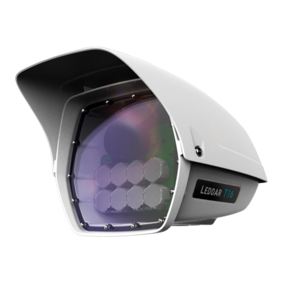
- Page 1 Model shown: Leddar™ T16 “Traffic” sensor Leddar ™ Solid-State LiDAR Traffic Sensor UIDE TF ID 013722...
- Page 2 This page intentionally left blank 2 | 72 © 2021 LeddarTech Inc.
- Page 3 Conditions, Product Warranty and End-User License Agreement carefully. Documentation available at www.leddartech.com, section “Resources.” Leddar™ Configuration software: this software is based in part on the work of the Independent JPEG Group. Keep this User Guide for future reference. 54A0043_V4.0_EN / Leddar T16 – User Guide...
- Page 4 DISCLAIMER LeddarTech ® shall not be liable for any errors or omissions herein or for any damages arising out of or related to this document or the information contained herein, even if LeddarTech has been advised of the possibility of such damages. Descriptions of products, including, but not limited to, specifications and drawings, and other related information contained in this document, are provided only to illustrate their operation and application examples.
-
Page 5: Table Of Contents
Distance Screw........................22 4.3............................. 23 LECTRICAL 4.4..........................23 NVIRONMENTAL 4.5....................24 OFTWARE YSTEM EQUIREMENTS INSTALLING THE LEDDAR T16 SENSOR ................... 24 5.1..................24 NSTALLING AND RIENTING THE ENSOR 5.2. T16 S ..................26 ONNECTING THE EDDAR ENSOR INSTALLING LEDDAR™... - Page 6 STATIC IP AND DHCP CONFIGURATION UNDER WINDOWS 7 AND UP ....58 APPENDIX B. MAKING CONNECTORS FOR THE ETHERNET CABLE ..........61 APPENDIX C. USING LEDDARCDEMO (SDK CODE EXAMPLE) WITH THE LEDDAR T16 ... 66 6 | 72 © 2021 LeddarTech Inc.
- Page 7 Fig. 7: Leddar T16 “Traffic” Sensor dimensions.................... 21 Fig. 8: Leddar T16 “Tolling” Sensor dimensions ................... 21 Fig. 9: Leddar T16 “Traffic” Sensor top view – Distances between mounting threads ......... 22 Fig. 10: Leddar T16 “Traffic” Sensor bottom view – Distances between mounting threads ......22 Fig.
- Page 8 Fig. 36: Horizontal scale setting areas (“Traffic” configuration) ..............50 Fig. 37: Horizontal scale setting areas (“Tolling” configuration)..............50 Fig. 38: Detection point coordinates (“Traffic” configuration) ................ 51 Fig. 39: Detection point coordinates (“Tolling” configuration) ............... 51 Fig. 40: Record Settings window ........................52 Fig.
- Page 9 Table 6: Leddar T16 configurations ......................16 Table 7: Ethernet cable ..........................17 Table 8: Key components ..........................17 Table 9: Leddar T16 general specifications ....................20 Table 10: Test conditions and detection range ..................... 20 Table 11: Leddar T16 mechanical specifications ..................20 Table 12: Leddar T16 electrical specifications ....................
- Page 10 Version History Version Description Date ( YYYY 54A0043_V1.0_EN Initial release 2019-02-06 • Reviewed section “Document Conventions” • Tables 6 and 9: deleted 48° Traffic configuration 54A0043_V2.0_EN 2019-03-28 • Tables 10 and 11: modified detection ranges and added notes • Table 21: described new Static Threshold Activation and 54A0043_V3.0_EN 2020-04-24 Offset features...
- Page 11 4535, boulevard Wilfrid-Hamel, Suite 140 Québec (Québec) G1P 2J7, Canada Québec (Québec) G1P 2J7, Canada + 1-418-653-9000 Phone 1-855-865-9900 8:30 a.m. – 5:00 p.m. EST + 1-418-653-9099 Support support@leddartech.com Website www.leddartech.com 54A0043_V4.0_EN / Leddar T16 – User Guide 11 | 72...
- Page 12 Document Conventions This document uses the following conventions: Name of menu > Shows the access path to menus under each section of the Leddar™ name of the window Configuration software. The names of buttons, menus, dialog boxes and the elements of the interface are Arial bold in bold type.
-
Page 13: Labels And Safety Information
IEC 62471:2006 (exempt lamp classification) Ingress protection IP67 FCC Part 15, Subpart B, Class A Electromagnetic Class A digital apparatus. Complies with the Canadian Interference-Causing compatibility Equipment Standard ICES-003. Compliant 54A0043_V4.0_EN / Leddar T16 – User Guide 13 | 72... -
Page 14: Introduction
Introduction 2.1. Definitions Table 3: Definitions Term Definition Sensing area of a sensor. The active grid measures the range of detected objects Active grid and must be centered on the zones that need to be monitored. It is represented by an overlay of the live video window (“Traffic”... -
Page 15: Underlying Principles And Lidar Fundamentals
2.2. Underlying Principles and LiDAR Fundamentals Created by LeddarTech, Leddar™ (light-emitting diode detection and ranging) is a unique sensing technology based on the LED illumination (infrared spectrum) and the principle of a light’s time of flight. The LED emitters illuminate the area of interest. The multi-segment sensor receiver collects the backscattered light and measures the time taken for the light to return to the sensor. -
Page 16: Intended Use And Description
Leddar™ T16 Solid-State LiDAR Traffic Sensor (hereafter referred to as “the sensor” or “Leddar T16”). The Leddar T16 Traffic Sensor is a 2D solid-state LiDAR that is specifically designed for traffic management systems from city to highway applications. Packaged in a weatherproof housing, the Leddar T16 ensures cost-efficient and highly accurate detection for various intelligent transportation system (ITS) applications, such as electronic tolling, traffic monitoring and traffic law enforcement. -
Page 17: Key Components
Receiver Emitter • Light emitter • Receiver lens • Diffuser lens 3.3. Front View Enclosure sunshade Receiver Camera LED emitters (8 x) Fig. 2: Leddar T16 “Traffic” Sensor front view 54A0043_V4.0_EN / Leddar T16 – User Guide 17 | 72... -
Page 18: Rear View
Receiver LED emitters (8 x) Fig. 3: Leddar T16 “Tolling” Sensor front view 3.4. Rear View Enclosure sunshade Ethernet connector Fig. 4: Leddar T16 “Traffic” Sensor rear view 18 | 72 © 2021 LeddarTech Inc. -
Page 19: Distance Measurement
3.5. Distance Measurement Distance is measured from the screw located on the sides of the Leddar T16 Sensor casing. Fig. 6: Distance measurement The dashed lines illustrate 1 of the 16 segments and the solid line indicates the distance measured by the sensor in that segment. -
Page 20: Specifications
Specifications 4.1. General Table 9: Leddar T16 general specifications Description Value Number of segments Horizontal x Vertical FOV 48° x 7.5°, 36° x 5.9°, 25° x 4.2°, 19° x 3.0°, 10° x 1.6° Resolution 3.00°, 2.25°, 1.63°, 1.19°, 0.56° Wavelength... -
Page 21: Dimensions
Compatible with standard traffic hardware 4.2.1. Dimensions 386 mm 259 mm 226 mm Fig. 7: Leddar T16 “Traffic” Sensor dimensions 277 mm 252.4 mm 208.7 mm Fig. 8: Leddar T16 “Tolling” Sensor dimensions 54A0043_V4.0_EN / Leddar T16 – User Guide... -
Page 22: Distance Screw
4.2.2. Distance Screw Fig. 9, Fig. 10 and Fig. 11 below show the distances between the mounting threads of the Leddar T16. 136.8 mm 25.4 mm Fig. 9: Leddar T16 “Traffic” Sensor top view – Distances between mounting threads 100.5 m 25.4 mm... -
Page 23: Electrical
86.7 mm 25.4 mm Fig. 11: Leddar T16 “Tolling” Sensor bottom view – Distances between mounting threads 4.3. Electrical Table 12: Leddar T16 electrical specifications Description Value Power supply IEEE 802.3at PoE+ (Power over Ethernet Plus), 56 VDC 54 V to 57 V (56 V nominal) -
Page 24: Software System Requirements
Installing the Leddar T16 Sensor 5.1. Installing and Orienting the Sensor The mounting bracket can be attached to the bottom or top of the Leddar sensor, as shown in the examples below. Fig. 12: Mounting position examples Required tools and materials: •... -
Page 25: Fig. 13: Orienting The "Traffic" Sensor With Reference Marks
These adjustments will vary according to the side of the road on which the sensor is installed. Fig. 14: Sensor position adjustments Refer to section 7.3.1.4 on page 42 for more information on the sensor orientation. 54A0043_V4.0_EN / Leddar T16 – User Guide 25 | 72... -
Page 26: Connecting The Leddar T16 Sensor
LeddarTech during the process. Fig. 15: Windows Security dialog box Follow the steps in the Welcome to the Leddar Configuration Software Setup Wizard. Refer to Appendix A for the detailed procedure on configuring the network with either a static IP or DHCP connection. -
Page 27: Fig. 16: Leddar Configuration Opening Window
On your computer desktop, click the Leddar Configuration icon ( ) to open the software. The following window appears: Fig. 16: Leddar Configuration opening window Click to connect to the sensor. The first time the sensor is connected to a computer, a few seconds are required for Windows to detect it and complete the installation. -
Page 28: Table 15: Connection Window
Unable to communicate. If the sensor does not respond to requests after some time, it is displayed in red. To disconnect from the sensor, click in the toolbar or select Device > Disconnect. To quit Leddar Configuration, select File > Quit. Table 15: Connection window Connection Details Description and Feature The status message is the connection status for a sensor, which indicates, e.g.,... -
Page 29: Leddar Configuration Software
Up to 10 sensors can be supported. Leddar Configuration Software The Leddar Configuration software allows you to view the detection measurements provided by the connected sensor. The detections may vary based on the configuration of the parameters. The main window can be resized manually or set to full-screen view. All dialog boxes that do not include a selection of action buttons at the bottom, such as Connect, OK or Cancel, are dockable at the top, bottom or right side of the main window. -
Page 30: Main Window
7.1. Main Window Once connected to the sensor, the main window of Leddar Configuration displays the following menus, toolbar and view. Fig. 19: Leddar Configuration “Traffic” configuration main window Fig. 20: Leddar Configuration “Tolling” configuration main window 30 | 72... -
Page 31: Table 16: Main Window Menus And Paths
View > Raw Detections View > Raw Detections Graph • “Tolling” configuration View > Device State View > Raw Detections See section “7.4 View Menu” on page 44 for more details. 54A0043_V4.0_EN / Leddar T16 – User Guide 31 | 72... -
Page 32: Table 17: Main Window Toolbar
See section “7.5 Settings Menu” on page 52 for more details. Click Help to access the following menu options: Help > User Guide Help Help > Leddar SDK Guide Help > About See section “7.6 Help Menu” on page 55 for more details. Table 17: Main window toolbar... -
Page 33: File Menu
Stop Data Logging event log of the sensor. The event log is displayed in text format. See section 7.2.2.2 for more details. Quit Select Quit to exit the Leddar Configuration software. 54A0043_V4.0_EN / Leddar T16 – User Guide 33 | 72... -
Page 34: Recordings (.Ltl File)
7.2.1. Recordings (.ltl File) Detection records provide a playback of detections recorded by a sensor. This visual information can be useful for verification, troubleshooting or training purposes. Detection records allow for a full data playback stored in an *.ltl file that you can later reload and replay. 7.2.1.1. -
Page 35: Fig. 22: Record Replay Window Upon Opening
Once you have completed a recording, you can review the recorded *.ltl file and extract parts of it. Click File > Replay. The Record Replay window appears. Fig. 22: Record Replay window upon opening Click to select an *.ltl file. 54A0043_V4.0_EN / Leddar T16 – User Guide 35 | 72... -
Page 36: Fig. 23: Record Replay Window With File Open
Fig. 23: Record Replay window with file open Table 19: Record Replay window Button/Feature Description Click Browse… to select the record file of the scene that you want to view again. Once selected, the name of the file will appear next to the button. -
Page 37: Data Logging (.Txt File)
To set up data logging file and launch data logging: To configure a .txt recording, click Settings > Data Logger. Click to select where to save the log and click OK. 54A0043_V4.0_EN / Leddar T16 – User Guide 37 | 72... -
Page 38: Device Menu
Table 20: Device menu options Option Description Device > Disconnect Click to disconnect the sensor from the software and return to Leddar Configuration. Device > Apply Select this option to confirm changes to the settings or click in the toolbar. -
Page 39: Configuration
To access this function, click Device > Configuration > Acquisition Settings. The Acquisition Settings function allows you to set the acquisition parameters for detecting objects or people. To apply new acquisition settings, click in the toolbar. 54A0043_V4.0_EN / Leddar T16 – User Guide 39 | 72... -
Page 40: Fig. 27: Acquisition Settings Dialog Box
Fig. 27: Acquisition Settings dialog box Table 21: Acquisition Settings Parameter Description Range Inter-channel interference noise mitigation Crosstalk is a phenomenon inherent to all multiple-segment time- of-flight modules. It causes a degradation of the distance meas- urement accuracy of an object when one or more objects with Enabled Crosstalk removal significantly higher reflectivity are detected in other segments at a... -
Page 41: Fig. 28: Network Settings Window
Select from the following five available options: • Auto-Negotiation Ethernet PHY Mode • 10 Mbps Half-Duplex • 10 Mbps Full-Duplex 54A0043_V4.0_EN / Leddar T16 – User Guide 41 | 72... -
Page 42: Fig. 29: Orientation Control Window
Parameter Description • 100 Mbps Half-Duplex • 100 Mbps Full-Duplex Select from the following two available options: • DHCP (Dynamic Host Configuration Protocol) Address Mode • Static See Appendix A for more details. 7.3.1.4. Orientation Control (Pan/Tilt Adjustment) To access this function, click Device > Configuration > Orientation. This feature is available with the “Traffic”... -
Page 43: Fig. 30: Video Settings Window
You can also use shortcuts by clicking the following icons in the toolbar. Table 24: Action icons Icon Description Click the Stop icon or select Device > Action > Stop Live Update to stop the continuous update of images and results. 54A0043_V4.0_EN / Leddar T16 – User Guide 43 | 72... -
Page 44: View Menu
Icon Description Click the Video camera icon or select Device > Action > Start Live Update to start continuous update of images and results. Video activation and settings preferences can affect the detection performance in real time. The Camera icon is used to take a high-resolution snapshot. You can also take a snapshot by selecting Device >... -
Page 45: Image Activation
This feature is available with the “Traffic” configuration only. It allows you to activate or deactivate the grid that appears in the main window. To change the color of the grid, select Preferences, then Leddar™ T16. See section 7.5.3 for more details. 54A0043_V4.0_EN / Leddar T16 – User Guide... -
Page 46: Raw Detections
7.4.4. Raw Detections To access this function, click View > Raw Detections. This window allows you to view detection values. It also provides filters to isolate segments and detection parameters. An object crossing the sensor beam is detected and measured. This detection is qualified by its segment position, distance and amplitude. -
Page 47: Table 28: Flag Values
Table 28: Flag values Bit position Bit = 0 Bit = 1 Invalid measurement Valid measurement Reserved Reserved Reserved Reserved Reserved Reserved Reserved Reserved Reserved Reserved Reserved Reserved Reserved Reserved 54A0043_V4.0_EN / Leddar T16 – User Guide 47 | 72... -
Page 48: Raw Detections Graph
7.4.5. Raw Detections Graph To access this function, click View > Raw Detections Graph. This feature is available with the “Traffic” configuration only. It allows you to view the segments. Fig. 33: Raw Detections Graph example The measurements are represented in a symbolic graph containing the 16 segments (white lines) originating from the sensor. -
Page 49: Fig. 34: Vertical Scale Setting Areas ("Traffic" Configuration)
Fig. 34: Vertical scale setting areas (“Traffic” configuration) Fig. 35: Vertical scale setting areas (“Tolling” configuration) 54A0043_V4.0_EN / Leddar T16 – User Guide 49 | 72... -
Page 50: Fig. 36: Horizontal Scale Setting Areas ("Traffic" Configuration)
Fig. 36: Horizontal scale setting areas (“Traffic” configuration) Fig. 37: Horizontal scale setting areas (“Tolling” configuration) You can hover the mouse over a segment to view the following information: • Segment • Distance (in meters) 50 | 72 © 2021 LeddarTech Inc. -
Page 51: Fig. 38: Detection Point Coordinates ("Traffic" Configuration)
• Amplitude Fig. 38: Detection point coordinates (“Traffic” configuration) Fig. 39: Detection point coordinates (“Tolling” configuration) 54A0043_V4.0_EN / Leddar T16 – User Guide 51 | 72... -
Page 52: Settings Menu
Record directory format, with the extension *.ltl, and can only be opened and viewed with the Leddar Configuration software. Record files can be quite large. Set the maximum file size as needed. The recording stops for the current file once it reaches the maximum file size and Maximum file size automatically switches the recording to another file. -
Page 53: Data Logger
See section “7.2.1.1 Setting Up Recording Settings” for more details. 7.5.2. Data Logger To access this function, click Settings > Data Logger. Fig. 41: Data Log Settings dialog box See section “7.2.2.1 Setting Up Data Logging” for more details. 54A0043_V4.0_EN / Leddar T16 – User Guide 53 | 72... -
Page 54: Preferences
To access this function, click Settings > Preferences. This feature allows you to change various settings related to window display. Fig. 42: Preferences window With the “Tolling” option, “Leddar T16” is not shown under General. Table 30: Preferences window options and settings Option... -
Page 55: Access Level
User Guide To access this function, click Help > User Guide. The User Guide option allows you to select and consult a PDF version of a user guide directly from Leddar Configuration. Select a user guide from the list to open a PDF version of the selected user guide. -
Page 56: Communication Protocol
• Verify that the T16 Sensor is connected. No power • Verify that the T16 Sensor is connected to an appropriate PoE+ port. • Verify that your computer is configured with a static IP address. • Verify that the cable is properly secured in the Ethernet port. -
Page 57: Maintenance
Do not use cotton-tipped applicators. If needed, clean the optical surfaces with isopropyl alcohol instead. For any questions or concerns on how to safely perform maintenance operations on the T16 Sensor, contact LeddarTech support at support@leddartech.com. Disposal Like any electronic equipment, the Leddar T16 Sensor contains environmentally unsustainable components. -
Page 58: Appendix A. Static Ip And Dhcp Configuration Under Windows 7 And Up
Appendix A. Static IP and DHCP Configuration Under Windows 7 and Up Part A – Configuring the Network for Static IP Mode You will lose Internet connection if you are not connected via other means. In Control Panel > Network and Internet > Network and Sharing Center, select Change adapter settings. -
Page 59: Fig. 46: Ethernet Properties Window
Insert the same subnet mask as the sensor (255.255.255.0 by default) in the Subnet mask field. Fig. 47: IP address and subnet mask Refer to section “6. Installing Leddar™ Configuration” once the configuration is completed. 54A0043_V4.0_EN / Leddar T16 – User Guide... -
Page 60: Fig. 48: Sensor Connection To Poe+ Switch
In the network connections, make sure that TCP/IPV4 is set to automatic. Fig. 49: Ethernet properties Fig. 50: IP address and subnet mask Refer to section “6. Installing Leddar™ Configuration” once the configuration is completed. 60 | 72 © 2021 LeddarTech Inc. -
Page 61: Appendix B. Making Connectors For The Ethernet Cable
Strip the cable jacket to approximately 1 in. (25 mm) and feed the cable through the plug housing (IP67 industrial modular connector). LeddarTech is not responsible for water infiltration if the IP67 industrial modular connector is not used. Fig. 52: Ethernet cable with jacket stripped and plug housing 54A0043_V4.0_EN / Leddar T16 – User Guide 61 | 72... -
Page 62: Fig. 53: Twisted Pairs
Untwist the wire pairs and separate them. Fig. 53: Twisted pairs Align the wires according to the T568B standard (see Figure 56). Do not remove the insulation of individual wires. White/orange Orange White/green Blue White/blue Green White/brown Brown Fig. 54: Cat 5e T568B wiring diagram 62 | 72 ©... -
Page 63: Fig. 55: Wires In The Load Bar
Slide the load bar until it sits against the cable jacket, then cut the wires to approximately ¼ in. (5 mm). Trim the remaining wire tips and retract the cable to leave about 1/32 in. (1 mm) of wire. Fig. 56: Trimming the wires 54A0043_V4.0_EN / Leddar T16 – User Guide 63 | 72... -
Page 64: Fig. 57: Inserting The Load Bar And Wires Into The Rj45 Plug
10. Hold the plug in position and rotate the cable fitting clockwise until tightened to a torque of 20 lbs-in. (2 Nm). 11. Install the sensor as described in section “5. Installing the Leddar T16 Sensor.” 64 | 72 © 2021 LeddarTech Inc. -
Page 65: Fig. 59: Rj45 Strain Relief Connector Kit (Other End Of The Ethernet Cable)
In step 1, instead of using the plug housing, use the yellow strain relief (see Fig. 59). Fig. 59: RJ45 strain relief connector kit (other end of the Ethernet cable) 14. Repeat steps 1 through 13 above for the other sensors. 54A0043_V4.0_EN / Leddar T16 – User Guide 65 | 72... -
Page 66: Appendix C. Using Leddarcdemo (Sdk Code Example) With The Leddar T16
Appendix C. Using LeddarCDemo (SDK Code Example) With the Leddar T16 When installing the Leddar Configuration software, select both products as shown below. You should see the Examples code in the Documents folder in C:\ ... Documents\LeddarTech, as shown below. - Page 67 Copy all the DLL files from C:\Program Files\LeddarTech\xtec. 54A0043_V4.0_EN / Leddar T16 – User Guide 67 | 72...
- Page 68 Paste the DLL files to the LeddarCDemo folder: 68 | 72 © 2021 LeddarTech Inc.
- Page 69 Open LeddarCDemo.vcxproj with Visual Studio and compile the Main.c 54A0043_V4.0_EN / Leddar T16 – User Guide 69 | 72...
- Page 70 The DOS window below appears: Select option 3. List Sensors to find the sensor with the address 192.168.0.10. Select options 1. Connect, then 1. Read Data. The code example below reads only 8 segments. 70 | 72 © 2021 LeddarTech Inc.
- Page 71 54A0043_V4.0_EN / Leddar T16 – User Guide 71 | 72...
- Page 72 More information on our offices worldwide can be found at: leddartech.com/contact-us Leddar, LeddarTech, LeddarSteer, LeddarEngine, LeddarVision, LeddarSP, LeddarCore, VAYADrive, VayaVision, XLRator and related logos are trademarks or registered trademarks of LeddarTech Inc. All other brands, product names and marks are or may be trademarks or registered trademarks used to identify products or services of their respective owners.