
Related Manuals for Hardi ALPHA EVO EcoDrive 5100


Summary of Contents for Hardi ALPHA EVO EcoDrive 5100
- Page 1 ALPHA 5100 EVO EcoDrive Original Instruction book 67790901-100 - Version 1.00 GB - 09.2017 www.hardi-fr.com...
- Page 2 Illustrations, technical information and data in this book are to the best of our belief correct at the time of printing. A s it is HARDI-EVRARD S.A.S. policy permanently to improve our products, we reser ve the right to make changes in design, fe atures, accessories, specifications and maintenance instructions at any time and without notice.
-
Page 3: Table Of Contents
Sommaire Sommaire 1 - EU Declaration EU Declar ation of conformity ..................................9 2 - General Safety Instructions Obligations and Liabi lity ........................11 Comply with the Instr uction Book ................................11 Be fore First Use of the Sprayer .................... - Page 4 Sommaire Sprayer Use ..........................................40 Lifetime ............................................41 Liquid System ............................42 Pump ..
- Page 5 Sommaire Operation ..........................................84 2-Wheel Ste ering mode ....................................84 ’Follower’ Mode ........................................85 Steer ing A xle Mode ...
- Page 6 Sommaire Liquid Fer tilizer ........................................129 Operating Limits ........................................131 Clean ing ............................
- Page 7 Sommaire Feed Pipe Clamp A sse mbly ..................................167 Feed Pipe Snap-Lock Assembly ................................167 Nozzle Holder Assembly ....................................167 Nozzle Pipe Assembly ....................................170 BoomPr ime One -Way Valve ..................................172 Adjustment of 3 -Way Valve .....................
- Page 8 Sommaire...
-
Page 9: Eu Declaration
1 - EU Declaration EU Declaration of con fo rmity As manufacturer : HARDI-EVRARD S. A .S. 21 rue du mai 19 40 62 990 BEAURAINVILLE FRA NCE hereby de clare that the following product ALPHA 5000 (variant 401MA-401MB-402MA-402MB-401HA-401HB-402H A-402H B) fulfils all the relevant provisions of the following Directives of the European Parliament and of the council: •... - Page 10 1 - EU Declaration...
-
Page 11: General Safety Instructions
To guide you in this matter, the issues concerning your work with the sprayer are listed below. However, HARDI do not accept liability that the issue s listed cover the requirements in the directive fully. This responsibility lies with the owner of the sprayer. - Page 12 2 - General Safety Instructions Article 2 Definitio ns For the pur poses of this Directive, the following terms shall have the following meanings: ‘work equipment’: any machine, apparatus, tool or installation used at work; (b) ‘ u se of work equipment’: any activity involving work equipment such as star ting or stopping the equipment, its use, transpor t, repair, modification, maintenance and servicing, including, in particular, cle aning;...
- Page 13 2 - General Safety Instructions Article 6 Work equipment invo lving specific risks When the use of wor k equipment is likely to involve a specific risk to the safety or health of workers, the employer shall take the measure s necessary to ensure that: (a) the use of work equipment is restr icted to those pe rsons given the task of using it;...
-
Page 14: Obligations Of The Ope Rator
Before first use of the sprayer, a sur ve yor must complete a statutor y inspection of the tractor and sprayer. Howe ver, the rules often allow the tractor and the sprayer to be inspected separately before being connected. Contact your local HARDI dealer for more infor mation on this inspection and when it has to be complete d. -
Page 15: Risks In Handling The Sprayer
• Improper ly executed re pair s • Spare parts used are not genuine HARDI spare par ts. If the operator de cides to use a spare par t, which is not approved by HARDI, the ope rator immediately assumes responsibility for any accident, damage or malfunction, which can be traced back to the use of this spare part. -
Page 16: Organizational Measures
2 - General Safety Instructions Organizational Measures This Instruction Book • must always be kept together with the spraye r • must always be e asily accessible for the operator Personal Protecti ve Equipment The ope rator must use the nece ssar y personal protective equipment as per the information pr ovided by the manufacturer of the plant protection product to be used, such as:: Chemical- resistant gloves Chemical- resistant and disposable overalls... -
Page 17: Representation Of Safety Symbols
2 - General Safety Instructions Representation of Safety Symbols Explanation of Symbols Safe ty symbols are use d in the following chapters throughout this Instr uction Book to designate, where the reader has to pay extra attention. The signal word (DANGER, WARNING, ATTENTION or NOTE) descr ibes the severity of the risk. The symbols have the following meaning: €... -
Page 18: Warning Signs On The Sprayer
The labels should always be clean and readable! Worn or damaged labels must be replaced with new ones. Contact your HARDI deale r for new labels. Note that not all labels shown hereafter will apply to your spr ayer - this depends on the sprayer mode l which labels apply. - Page 19 2 - General Safety Instructions Risk of squeezing! Risk of squeezing Stay clear of r aise d and unsecure d loads. Never reach into the crushing danger area as long as parts are moving. Grapping area! Risk of falling off! Manual handling of the boom etc.
-
Page 20: Safety And Protection Equipment
2 - General Safety Instructions Safety and Protection Equipment Safety at Start-up Each time befor e the sprayer is star te d up, all the safety and protection equipment must be pr operly attache d and fully functional. Check all safety and protection equipme nt regularly. Repair or replace the equipme nt as nee ded. Faulty Safety Equipment Faulty or disassembled safety and protection equipment can lead to dangerous situations. -
Page 21: Informal Safety Measures
2 - General Safety Instructions Informal Safety Measures Addition al Safety Instruction s Together with the safe ty information in this Instruction Book, also comply with the ge ner al and national r e gulations related to A. Accident pre vention B. -
Page 22: Operator Training
2 - General Safety Instructions Operator Training Auth orized Person s Only those pe ople who have be e n trained and instr ucted may work with/on the s prayer. The oper ator must cle ar ly specify the r esponsibilities of the pe ople in char ge of operation and mainte nance wor k. People be ing tr ained may only work with/on the sprayer under the supervision of an e xperie nced operator. -
Page 23: Safety Measures In Normal Operation
2 - General Safety Instructions Safety Measures in Normal Operation Protecti on Equi pment Only ope rate the sprayer if all the safety and protection equipme nt is fully functional. Check the spr aye r at least once a day for visible damage and check the function of the safety and protection e quipment. P rodu cts man ufactu rer responsibil ity The cor rect use and precautions to be taken for the proper use of the products are the sole responsibility of the products manufacturer, through the information on the packaging or other product sheets made available by this manufacturer. -
Page 24: Residual Energy
2 - General Safety Instructions Residual Energy Po ssibl e Dan gers Note that there may be residual energy from mechanical, hydraulic, pneumatic and electric / electronic par ts on the sprayer. Use appr opriate measur e s to inform the operators. Prevent any accidents from happening due to residual energy. -
Page 25: Service And Maintenance Work
2 - General Safety Instructions Service and Maintenance Work Statutory Inspection A surveyor must complete a statutory inspection of the tractor and sprayer prior to connecting the two. However, the r ules often allow the tractor and the sprayer to be inspected separately before being connected. Each countr y should re gulate the level and fre quency of this inspection. -
Page 26: Design Changes
Any expansion or modification work shall require the written approval from HARDI. Only use modification and accessor y parts approved by HARDI, so that the type appr oval or other de sign approvals remain valid in accordance with national and inte rnational regulations. -
Page 27: Cleaning And Disposal
2 - General Safety Instructions Cleaning and Disposal Environ men tal Protection Carefully handle and dispose of any materials used, in par ticular • When car rying out work on oiled or lubricated sprayer parts. • When cleaning using solvents. Always follow local legislation regarding disposal. -
Page 28: Workstation
2 - General Safety Instructions Workstation In ten ded Pl ace fo r Operato r There may be only one person s itting in the driver's seat of the tractor connected to the sprayer. This is the intende d wor kstation for operating the sprayer. Risks of Non-Compliance During the operation or tr anspor t of the sprayer: If another person disturbs or inter fe res with the operator, or if the operator is trying to operate the sprayer from other places... -
Page 29: If The Safety Information Is Ignored
2 - General Safety Instructions If the Safety Information is Ignored Po ssibl e Risks an d Dan gers Non- compli a nce with the safety information: • Can pose a danger to people, to the environment and to the spr aye r •... -
Page 30: Safety Information For Operators
2 - General Safety Instructions Safety Information For Operators G en eral Safet y and Accident Preventi o n Before use or starting up the spr aye r and the tr actor, always check the ir • road-worthiness • oper ational safe ty Risk of crushing, cutting, catching, sque ezing, getting trapped, being dr awn in or being struck by sprayer parts due to inadequate road-wor thiness and operational safety. -
Page 31: Road Transport
2 - General Safety Instructions Road Transport When driving on public roads or highways with the sprayer coupled to the tractor, the following instructions must be followed. Failure to do so will create a r isk of: • traffic accidents or fatalities! •... -
Page 32: Hydraulic System
• It is leaking • Reinforcement material inside the hose is visible due to cracks in the outer layers. O nly use genuine HARDI hydr aulic hose line s. If you ar e injured by hydraulic oil, contact a doctor immediately. -
Page 33: Use Of The Sprayer
2 - General Safety Instructions Use of The Sprayer Before starting wor k, ensure that you understand all the equipment and actuation elements of the s prayer and their function. The re is no time for this when the sprayer is already in operation. Only wear tight clothes. -
Page 34: Field Sprayer Operation
2 - General Safety Instructions Field Sprayer Operation Observe the recommendations from the manufacturer of the crop prote ction product in respect of: • Per sonal protective equipment • Warning information on exposure to cr op protection products • Regulations on dosing, applications and cle aning. When there will be exposure to the crop protection product: •... -
Page 35: Service Work Precautions
2 - General Safety Instructions Service Work Precauti ons Before carrying out any ser vice work, all of the following instructions must be followed in order to prevent damages to the sprayer, injuries and fatalities: • Do not walk under any part of the spraye r, unless it is secured. The spray boom is se cured when placed in the transport brackets •... -
Page 36: Service And Maintenance
Stay below the maximum speed (rpm) suitable for the PTO shaft. When r eplacing spare parts, use suitable tools and personal protective equipment. Spare parts must at least meet the specified te chnical requir ements of HARDI. This is ensured thr ough the use of genuine HARDI spare parts. -
Page 37: Description
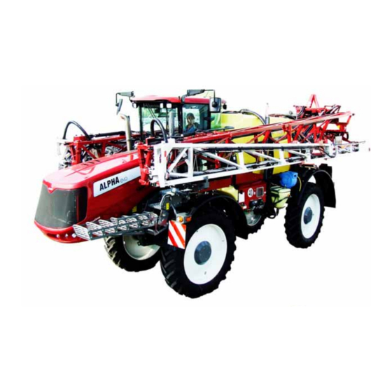
3 - Description General Info View 1. Tank lid 9. External engine controls 2. Main tank 10. Hand wash tank 3. Central frame 11. Cab ladder 4. External cleaning system 12. Working lights 5. Turbo Filler 13. Dipped beam lights 6. -
Page 38: Identification Plate
An identification plate indicating data for the sprayer is mounte d in the stee l frame near the front of the sprayer on the right- hand side. HARDI-EVRARD 62990 BEAURAINVILLE Marque N°... -
Page 39: Data
3 - Description Data HARDI-EVRARD 62990 BEAURAINVILLE Marque N° de serie - 1 - Type-Variante Version - 2 - Année fabrication - 3 - - 7 - Masse maximale admissibles PTAC - 8 - Essieu1 / attelage PTRA - 4 -... -
Page 40: Sprayer Use
Sprayer Use The HARDI spraye r is for the application of crop protection che micals and liquid fer tilizers. The equipment must only be used for this pur pose. It is not allowe d to use the sprayer for any other pur poses. -
Page 41: Lifetime
To obtain this successfully, these instructions should be followe d: • All service and maintenance work must be completed in due time • Repair any damages par ts as quickly as possible • Replace or change spare par ts as instructed • Only use original HARDI spare parts. -
Page 42: Liquid System
3 - Description Liquid System Pump The design of the diaphragm pump is simple, with easily acce ssible diaphragms and valve s, which ensures that liquid does not contact the vital par ts of the pump. Pump model 464/10 or 464/12 Valves an d Symbol s The possible functions of valves are distinguished by coloured identification on the function labels. - Page 43 3 - Description E xte rnal cleaning ( White s ymbol The valve is used for cleaning the outside of the sprayer Ma in Tank dra ining ( White s ymbols The handle of the drain valve is turned to empty the main tank Close main tank Open main tank drain valve...
-
Page 44: Dynamicfluid4 Pressure Regulation
3 - Description DynamicFlui d4 Pressure Regulation Traditional fluid regulation star ts, when the nozzles are opened. With DynamicFluid4 (DF4), the regulation is a continuous process, even if the nozzles are closed. A synthetic or ceramic disc and a stainless steel disc regulate the pressure and ensure quick reaction and zero le akages. - Page 45 3 - Description Regulation va lve func tion diagram Spray job begins Start condition: μ Controller is turned OFF. Pump is turned OFF . ATTENTION! Auto mode icons shown, but could be Manual or Increment steps icons, depending on driver selection. Pressure SmartValve to Pressure draining/TurboFiller, suction SmartValve to Main tank, have water in Main tank.
-
Page 46: Filters
3 - Description Filters Filter s on your spraye r are there to protect the components and prevent nozzle blockage. An Easy Clean suction filte r is fitted in the working zone. A Cyclone pressure filter is fitted on the sprayer’s right side just in front of the hose re el, hidden be hind the right front cover. It has a built-in self-cleaning function. - Page 47 3 - Description Cycl one Filter With the CycloneFilter, any impurities in the spray liquid will be cleaned out and returned to the main tank via the return flow. Function diagram: 1. Filter lid 2. Piping from pump 3. Piping to boom 4.
- Page 48 3 - Description TurboFiller The TurboFille r is where you add the chemicals to be mixed with water in the main tank. Capacity: approximately 35 litres. By oper ating the valves (A) on the side and valve (B) of the TurboFille r (C), you can do the following: •...
- Page 49 3 - Description Clean water Tank A clean water tank is located on the left side of the sprayer The water in this tank is for hand washing with clean water from the tap Capacity: approximately 15 litres.
- Page 50 3 - Description Boom Prime BoomPr ime is a low pressure circulation system, which primes the spray boom tubes pr ior to spr aying, ensuring a homogeneous fluid in the boom tubes and in the main tank. Be low the illustration shows the BoomPrime system for the boom.
-
Page 51: Diagram - Liquid System With Optional Extras
3 - Description Diagram - Liqu id system with option al extras 1. Suction Smar tValve 23. Drain valve 2. Pressure SmartValve 24. Sprayer boom 3. Agitation/Cleaning valve 25. Flowmeter 4. Chemical container cleaning valve 26. Bypass valve 5. TurboDefle ctor ON/OFF valve 27. -
Page 52: Diagram - Intelligent Liquid System With Optional E Xtras
3 - Description Diagram - Intel ligent liqu id system with option al extras 1. Suction Smar tValve 25. Flowmeter 2. Pressure SmartValve 26. Distribution valves 3. Agitation/Cleaning valve 27. Sensor for pressure gauge 4. Chemical container cleaning valve 28. Suction In-line filter 5. -
Page 53: Twin Air Technique
3 - Description TWIN Air tech niqu e G en eral in fo With TWIN air assistance energy is added to the spray droplets to improve control with the spray liquid. The main purpose of the T WIN angling system is to counteract for the negative influence which wind direction and dr iving speed have on the quality of the spray job. -
Page 54: Boom
3 - Description Boom Standard Boom Features • Individual tilt of boom wings. (HAZ boom type only) • Each boom wing is 2-folded. • Alte rnative boom width: The boom may be used in 1/2-folded boom width. • Spring-loaded breakaway section. •... - Page 55 3 - Description Ava ilable Working Widths - A luminium Full working width 1/2-folded width Type (meters) (meters) RH A RH A Ava ilable Working Widths - TWIN Force Full working width Type (meters) Force TWIN Force Force TWIN Force Force TWIN Force Force...
-
Page 56: Grip Controls
3 - Description G rip controls The grip controls the following: A. Status LED. B. Boom section controls. C. Main ON/OFF. D. Tilt. E. Boom height. F. Boom slant. G. TWIN controls. -
Page 57: Engine
3 - Description Engine Rat ing plates of en gine and aftertreatment gas system The type (A), serial number (B), and technical data are stamped on the rating plate 1. Rating plate of the diesel particle filter 2. Rating plate of the SCR catalyst For all information, please provide the type and the engine serial number Exhaust gas after-treatment... - Page 58 3 - Description Diesel particles filter The combustion of diesel fuel results in soot, which is separated in the diesel particle filter. This must be regene rated as the contamination with soot increases. That means that the soot in the diese l par ticle filter is burned. The regener ation is based on a continuous regeneration process, which is activated as soon as the exhaust temperature of 250 °C is e xceeded at the inlet of the exhaust gas after-treatment system.
-
Page 59: Cabin
3 - Description Cabin Description 1. Filter air inlet 2. Adjustable air vent 3. Air circulation for demisting 4. Air recirculation gr atings Catégorie 4 conforme à l’EN 15695:2010 Category 4 according to EN 15695:2010 In compliance with Standard EN 15695 , the cab is equipped with: •... -
Page 60: Description Of Driver's Seat
3 - Description Description of driver's seat ALPHA Evo EcoDrive is fitted with high quality professional seats. A user guide for the seat is supplied separately. You should read it in full before using the vehicle for the first time, and comply with the safety instr uctions on how the seat oper ate s. 1. -
Page 61: Control Pane L
3 - Description Co ntrol Panel 1. Interrupteur Ouver ture / Fermeture de la passe relle. 11. Inter rupteur Marche/Ar rêt du systè me 4 roues directrices automatique. 2. Interrupteur de réglage de la vitesse de rotation de la pompe de pulvé risation. 12. -
Page 62: Gener Al Description Of Oper Ator's Seat
3 - Description G en eral descripti on of operator's seat 1. 4-whee l drive control pedal 6. Multi-function display 2. Adjustable steering column 7. Side console 3. Brake pedal 8. Re friger ate d lunch box 4. Throttle pedal 9. -
Page 63: Cabin Ce Iling Controls
3 - Description Cabin ceili ng control s HI HI 1. 2-position windscree n wiper switch (permanent, 9. Non utilisé. intermitte nt) switch 10. Température sensor. 2. Windscreen washer switch. 11. Wing mirror adjustment switch. 3. Front working headlights switch. 12. -
Page 64: 4-Wheels Stee Ring (Standard)
3 - Description 4-Wheels Steering (stan dard) 1. Gre en indicator - Rear wheels aligned. 2. Blue indicator - 4-wheels engaged. 3. Gre en indicator - Front wheels aligned. 4. Automatic/ Manual mode Steering colum n Desc ription 1. Wheel steering move up or down handle 2. -
Page 65: Aluminium Hydraulic Controls
3 - Description Lights controls Alu minium Hydraulic controls Inner wings s im ultaneously controlled . 1. Not used 2. Right and left exte nsions. 3. Le ft outer section 4. Folding left and right inner sections. 5. Right outer section. 6. -
Page 66: Haz Boom Hydraulic Function Controls
3 - Description Inner and outer wings independently controlled 1. Not used. 2. Not used. 3. Folding left outer sections. 4. Folding left inner sections. 5. Folding right inne r sections. 6. Folding right outer sections HAZ boom hydraulic fun ction contro ls This configuration relates to spr ayers equipped with the HAZ central frame with simultaneous control of the inner and outer sections. - Page 67 3 - Description Auto Sl ant When the AutoSlant function is installed, sensors place d on the boom are used to adjust the main slant angle of the boom relative to the ter rain. To spray efficie ntly on hilly te rrain, it is important to adjust the boom to be paralle l to the terrain. AutoTerrain When the AutoTerrain function is installed, sensor s placed on the boom are used to adjust the angle of each boom side relative to the ter rain.
-
Page 68: Multi-Function Display
3 - Description Mu lti-fun ction display General info The multifunction display manages the data for the engine and the hydraulic transmission of the self-propelled, such tachometer, engine temperature, hydraulic pressure, fuel level, etc... ) . It also allows you to select operating modes (speed limits, traction control, etc..), and alarms related to the engine and hydraulic transmission. -
Page 69: Transmission
3 - Description Transmission Diff-Lo ck differential lockin g front/back General Info The Diff-Lock system is only suitable on ALPHA Evo EcoDrive versions 40 or 50 km/h. The controller drive a hydraulic valve ’ ’ located between the front and rear hydraulic circuit. When the valve is controlled, the hydraulic circuit of each pump becomes independent. - Page 70 3 - Description...
-
Page 71: Sprayer Setup
4 - Sprayer Setup Cabin Recommendat ions before installing th e filter • Read carefully this instruction book before proceeding. Keep this instructions for re tain consultation, • Before taking in place the filter, check the packaging is not damaging. Do not install a filter if the cardboard is rugged. •... -
Page 72: Unloading The Spr Ayer From The Truck
Manuel d’utilisation 67786201-100 - Version 1.00 F - 07.2011 3. Multi- jet spray 4. ISO nozzle disc www.hardi-fr.com www.hardi-fr.com 5. Table of ISO nozzle flow rates 6. Drain plugs (rinse tank-hand wash tank-storage box) 7. Gr aduated pot 8. Hydraulic pump lever (brake release - open the bonnet) 9. -
Page 73: Pr Ecautions Before Putting The Sprayer Into Operation
4 - Sprayer Setup Precaution s befo re puttin g the sprayer in to operation Your sprayer is protected by a re sistant lacquer coat. Howe ver, we recommend regular application of a layer of anti-corrosion lubricant on all metal par ts to avoid plant protection chemicals and fertilisers damaging the paintwork. If this is done before the sprayer is put into oper ation for the first time, it will be easier to clean the sprayer and keep the paintwor k clean for many years. -
Page 74: Spraying
4 - Sprayer Setup Spraying Spraying pump • Screw the plug (1) (if necessary) in the 464 pump. • Fitting the nozzles Install appropriate nozzles to achieve optimum spray quality • Place the nozzle filter (1) in the nozzle nut (2) •... -
Page 75: Boompr Ime Adjustment
4 - Sprayer Setup Boom Prime Adjustmen t The BoomPrime system works within a fixed pressure range of around 3 bar, but it must be adjuste d for the specific spray job (due to different choice of nozzles etc.): 1. Unfold the spray boom and star t the PTO. 2. -
Page 76: Altering The Track Width
4 - Sprayer Setup Alterin g the track width Track width (m) for ground clearance 1.20 m IF 320/90 VF 380/90 R46 420/80 R46 460/80/ R42 520/85 R42 650/65 R38 VF 380/90 R50 Rim offset +125 Axle type 1.76 1.82 2.05 1.91 2.14... -
Page 77: Tyres Inflate Pressure
4 - Sprayer Setup Proce dure for Altering the tra ck w idth The track width of the sprayer can be alte red by sliding the axle according to the table above: • Loosen bolts (1 ) and clamping screws (2) •... - Page 78 4 - Sprayer Setup...
-
Page 79: Operation
5 - Operation Driving Startin g up and shu tting down th e eng ine ÷ NOTE! Before star ting up the engine, check the level of the engine oil, coolant, fuel and hydraulic oil. S tarting up • Turn on the battery switch to «CONTACT» position •... -
Page 80: Travelling And Braking
5 - Operation μ If errors messages appears on the display and an audible alarm sounds, you must stop the engine immediate μ Always start up engine before starting up HC950 0 controller S hutting down • Place the grip to neutral position to stop the machine. •... -
Page 81: Parking Brake
5 - Operation Parki ng brake The parking brake is used to kee p the machine at a standstill. It acts on discs incorporated into the front and rear hydraulic motors. The br akes are activated when the hydraulic pressure reaches ze ro.: E ngage the parking bra ke •... -
Page 82: Steering - Automatic 4-Wheel Steering Version (Standard)
5 - Operation Steering - automatic 4-wheel steering version (standard) G en eral in fo rmation The automatic 4-whee l steer ing is made up of two position sensors fitted on the front and rear rods, a 4-wheel steering activation pedal, a switch and indicators on the control panel. 1. -
Page 83: Driving In 4-Whee L Steer Ing
5 - Operation Driving i n 4-wh eel steerin g In this mode, the front and rear whe els turn in opposite dire ctions • Press on the switch to activate [AUTO] mode • Press the pedal and turn the stee ring wheel until the front wheels are in a str aight line. -
Page 84: Steering - Automatic 4-Ws
5 - Operation Steering - Automatic 4-WS G en ral info The 4-wheel steer ing system with crab steering is made up of potentiometer s placed on the front and rear axle, a pedal in relation with the selector mode and the gr ip. Operation When the machine is started, the 4-WS system is operational. -
Page 85: Follower' Mode
5 - Operation ’Follower’ M ode In this mode, the front and rear wheels stee r in the opposite direction, so that the rear wheels pass through the traces of the front wheels. For maximum accuracy, the system takes into account the distance be twee n the axles (wheelbase ) and the speed of the machine. -
Page 86: Manual Mode
5 - Operation Operation in ’Roa d’ 1. Select 4-Wheels Steering mode 2. Select «Road» mode 3. Push the gr ip towards to move the machine 4. Press and hold the pedal to engage the ’Steering Axle’ mode • Release the pedal to return to 2-Whe el Steer ing μ... -
Page 87: Slope Counter-Steering Function
5 - Operation Slope cou nter-steerin g functio n When you activate the 'slope counter-steering' function you can offse t the track of the trailer device to the left or right. The direction in which the track is offset depends if the slope climbs or falls to the left or r ight of the machine. The aim of the 'slope counter-steer ing' function is to avoid the sprayer driving obliquely to the direction of work on a slope. -
Page 88: Hydraulic Track Adjustment (Optional)
5 - Operation Hydraulic Track Adjustment (optional) HTA control unit display 1. Forward Spe ed status. 2. Scrolling numbers (0 to 9). 2.20 3. Retracting Track button. 4. Valid button. 5. Extending Track button 6. Moving the cursor. 7. Status indicator. 8. - Page 89 5 - Operation Defe cts in the ope ration Defects in the operation may be caused by: • A forward speed out of the required speed range, while changing the track. • One or more wheels have not reached their position after 30 seconds (rut, me chanical, hydr aulic or electronic defaults). In the se cases, the status indicator (1) flashes.
-
Page 90: Transmission And Engine Operation
5 - Operation Transmission and engine operation G en eral in fo This chapter describes how to use the control terminal for transmission and engine management In fo rmation messag es • Press on button to scroll the following me ssages Engine overheating Oil engine pressure 0 to 100%. -
Page 91: Engine And Transmission Manage Ment
5 - Operation Eng ine an d transmission m an ag ement E CO mode • Press on button to se lect the message «ECO» • Press on button to engage or disengage the ECO mode ECOD RIVE engaged ECODRIVE disengaged Setting s driving m ode •... -
Page 92: Automotive (Road) Mode
5 - Operation hange from Road m ode to Field, Uphill, downhill 1. Place the grip in neutral position. 2. Turn the speed sele ctor on one of the 3 positions. 3. Increase the speed engine to a minimum of 1500 r.p.m 4. -
Page 93: Comfort, Normal, Power Mode
5 - Operation Braking ans stopping in AUTOMOTIVE m ode • To slow down, pull more or less the grip to neutral position or release the throttle pedal, the engine spee d automatically adapts to the travel speed of the machine. •... - Page 94 5 - Operation kmh / kph • COMFOR T: Progressive acceleration. • NORMAL: Inter mediate acceleration. • POWER : Reactive driving. S elect Drive M ode • Press on button to display the menu • Press on button again to navigate to the drive mode menu •...
-
Page 95: Ecodrive Mode
5 - Operation EcoDri ve Mode The EcoDrive function optimizes the engine speed and transmission depending on the transmission power required. The EcoDrive mode allows a significant reduction of fuel consumption and noise level of the machine. ÷ Engine speed continuously adapts depending on the power required to dr ive the machine. E nable / Disable EcoDrive func tion •... -
Page 96: Limitation Of Travel Speed In Automotive Mode
5 - Operation Limitation o f travel speed in Automo tive mode The Evo EcoDrive sprayer are standard equipped with a travel speed limitation in Automotive mode. It keeps a constant travel spe ed when the grip is pushed fully forward •... -
Page 97: Engine R.p.m. Limitation
5 - Operation Eng ine r.p.m. lim itatio n ALPHA e vo EcoDrive sprayers are equipped as standard with an engine r.p.m. limiter ÷ Engine r.p.m. limitation is only active in Fie ld, Uphill, Downhill modes. E nable / disable the engine r.p.m. limiter •... -
Page 98: Electronic Traction Control (Sa Pe)
5 - Operation Electronic Traction Contro l (SAPE) The traction control system can be switched on at any time, in "ROAD" or "FIELD" modes ÷ The regulation goes into standby mode when the tr avel spee d is higher than 20 kph. •... - Page 99 5 - Operation Message AdBlue Level (%) Performances moteur Engine warning lamp OFF > 15% 54.5 54.5 rpm x100 Engine warning lamp OFF Alarm lamp ON < 15% Engine warning lamp flashes (2 sec.) Alarm lamp ON < 10% Beep sound Engine warning lamp flashes (1 sec.) Alarm lamp ON Stage 1...
-
Page 100: Operation Monitoring
5 - Operation Operation m onitori ng E lec tronic engine control The status are displayed by the er ror lamp. The system monitors the condition of the engine and itself. • Function test - Ignition on, er ror lamp lights up for approx. 2 se conds and then goes out - Check the error lamp if there is no reaction after switching on the ignition. -
Page 101: Error Messages
5 - Operation Erro r messages When an operating anomaly occurs, an er ror message is displaye d accompanied by a beep sounds continuously. If the message reads « STOP» the engine must be stopped immediately and the checks carr ied out. The message and beep can be cancelled by pressing buttons (2) and (3) for 2 seconds. -
Page 102: Severity Of Engine Defects
5 - Operation Severity of engi ne defects The messages and the associated warning lamp indicates the severity le vel of engine faults Messages Engine warning lamp Note Severity step 1 Minor event Severity step 2 Reduction performance Flashes Severity step 3 STOP STOP IMMEDIATELY THE ENGINE The DTC (Diagnostic Trouble Code) message indicates the number of er rors on the motor:... -
Page 103: Exhaust Gas Aftertreatment System With Scr
5 - Operation Exhaust gas aftertreatment system with SCR Norm al Ope ration Under normal oper ating conditions (exhaust tempe rature > 250 °C), the filter contamination with soot remains in a permissible range and no actions are necessary. The regene ration lamp is off. •... -
Page 104: Implementation Of The Standstill Rege Neration
5 - Operation Im plementati on of the standstill regeneration The engine must be brought into a «safe state» for the re generation: • Shut down the engine on an open terrain at a safe distance to flammable objects. • Warm up the engine; the coolant temper ature must reach at le ast 75°C. -
Page 105: Engine Anti-Stall
5 - Operation Regeneration m essa ges Messages Warning lamp Power reduction Note Normal Operation Engine Warning lamp is off Engine Warning lamp is off Support mode Engine Warning lamp is off Standstill regeneration required Approval by the operator required Engine Warning lamp is on Standstill regeneration required Approval by the operator required... -
Page 106: Hydraulic Oil Too Low
5 - Operation Hydrau lic oil too l ow This message appears when the hydraulic oil leve l is too low. This requires an immediate shutdown of the machine. μ A too low level of hydraulic oil can lead to overhe ating the hydraulic system or damage the transmission •... - Page 107 5 - Operation Gangway ma nual control ÷ NOTE! The retractable gangway automatically moves away when the engine is shut down. If the machine is fitted with a LPA5 central frame , it may in case of ele ctr ical or hydraulic failure, the retractable gangway does not deviate from the cab.
-
Page 108: Cabin
5 - Operation Cabin Air con dition ing Desc ription control panel 1. Ventilation control knob 6. Temperature knob 2. Temperature inside or outside of the cab 7. Pressurisation indicator light 3. Cab pressurisation button 8. Air conditioning button. 4. LCD screen 9. - Page 109 5 - Operation 3. A/C compressor is oper ated or no ope rated, depending of the position of the air conditioning knob position 4. The pre ssurisation blower is operated or not operated, depending of the pressurisation knob position 5. Icons on the screen the oper ating mode selected 6.
-
Page 110: Pr Essurization Operating Mode
5 - Operation LO mode When the tempe rature control knob is in «LO» position, the ATC control module forces the system as follows: When the tempe rature knob is in «LO», the ATC control module • Water valve is closed •... -
Page 111: Default Codes
5 - Operation The flap fresh air is open. Function Depressurization cabin LED When overpressure button is « ON», after 30 seconds a pressure switch gives information of measure of the difference between inside and outside pressure of the cabin. If the cabin: - is pressurized the led is ON - isn’t pressurized the led is f lashing at 1Hz frequency. -
Page 112: General Info
• Spraying speed. Sprayer Use The HARDI spraye r is for the application of crop protection che micals and liquid fer tilizers. The equipment must only be used for this pur pose. If the sprayer is to be used for any other purposes than the ones descr ibed in this instruction book, a new risk asse ssment and a wor kplace assessment must be comple ted for this use. -
Page 113: General Info
• Spraying speed. Sprayer Use The HARDI spraye r is for the application of crop protection che micals and liquid fer tilizers. The equipment must only be used for this pur pose. If the sprayer is to be used for any other purposes than the ones descr ibed in this instruction book, a new risk asse ssment and a wor kplace assessment must be comple ted for this use. - Page 114 The labels must be readable when operating the sprayer. Damage d or unreadable labels must be replaced. The symbols are explaine d here Symbol on label Symbol description Label color HARDI item number Suction from main tank Black / Blue 97809900 Suction from Rinse Tank...
- Page 115 Unintended boom movements may cause contact with ove rhead power lines, causing a r isk of fatal accidents. μ ATTENTION! A label (HARDI item no. 9784 48) follows the spr ayer. This label must be placed in the cabin visible from the operator’s seat.
-
Page 116: Manoeuvring Of The Boom
5 - Operation Mano eu vring of th e Boom Applicable for HC 6500 / HC 8 600 / HC 9600 / ISOBUS. ÷ WARNING! The folding functions must only be operated, when the sprayer is stationary! Failure to do so will damage the boom. - Page 117 5 - Operation Liquid System G en eral In fo Please refer to the Spray Technique book for instructions on the use of filters, nozzles etc., and their combination in use with specific spraying applications. Quick Reference - Operation In the following diagram, the handle positions for different options are described.
-
Page 118: Filling/Washing Location Requirements
ATTENTION! Legislation and requirements vary from country to countr y. Always follow local le gislation in force. μ ATTENTION! It is the responsibility of the sprayer owner/operator to comply with all relevant legislation. HARDI cannot undertake any responsibilities for incorrect operation and use. -
Page 119: Filling Through Tank Lid
5 - Operation Filling Through Tan k Lid The tank lid is provided with a hinge (1) so it can be lifted. A locking system (2) prevents it from being opened. Opening: • Unlock and turn the lid anticlockwise then lift. Clos ing: •... -
Page 120: External Filling Device
5 - Operation External Fi lling Device The External Filling Device is operated as follows: 1. Remove cove r and connect suction hose to the suction manifold. 2. Turn pressure Smartvalve to ’ ’ Main tank’ ’ ’ 3. Turn handle on Exter nal Filling Device valve towards Filling Device 4. -
Page 121: Filling Of Clean Water Tank
5 - Operation Filling of Clean water tan k To fill the clean water tank: 1. Remove the scre w cap 2. Fill with clean water 3. Refit the screw cap Volume 15 litres For use of clean wate r The water from this tank is for hand washing, cleaning of clogged nozzles e tc. - Page 122 5 - Operation Safety Precaution s - Cro p Protectio n Chemicals Always be careful when working with crop protection chemicals! ± WARNING! Always wear proper protective clothing be fore handling chemicals! Personal protec tion Depending on chemical type, protective ge ar/equipment should be worn to avoid contact with the chemicals, such as: •...
-
Page 123: Operating The Turbofiller
5 - Operation Operating the TurboFiller The TurboFille r is where you add the chemicals to be mixed with water in the main tank. Capacity: approximately 35 litres. Before Use • raise the handle (A) to unlock the position of the TurboFiller. •... - Page 124 5 - Operation TurboFiller S uc tion Valve The valve is used simultaneously with the TurboFiller. The valve has 2 settings: Continuously open or spr ing-loaded normally closed. Open the valve by lifting the leve r up, whe n chemicals are to be filled into the TurboFiller and transferred to main tank.
- Page 125 5 - Operation Filling Liquid Chemicals U sin g the TurboFiller μ ATTENTION! We advice to use the TurboFiller, when you fill chemicals on the sprayer. 1. Fill the main tank at least 1 /3 with water (unless othe rwise stated on the chemical container label).
-
Page 126: Filling Powder Chemicals Using The Turbofille R
5 - Operation 9. Turn the agitation valve towards “agitation”. μ ATTENTION! If foaming is a problem, tur n down the agitation. 10. When the spray liquid is well agitated, turn handle of the pressure Smar tValve towards “spr aying” position. The agitation continues during spraying of the crop. -
Page 127: Turbofiller Rinsing
5 - Operation 7. Flush the TurboFiller with clean wate r from the r insing tank or from an e xter nal tank by shifting to suction. The TurboFiller suction valve must be ope n for at least 20 seconds after the rinse water is no longer visible in the hopper, in order to completely empty the transfer hoses into the main tank. -
Page 128: Boompr Ime
5 - Operation 2. Simultaneously press the Chemical Containe r Cleaning lever and the TurboFiller suction valve. This rinses the chemical container with the flushing nozzle, while the rinsing liquid is emptie d out of the TurboFiller. TurboFiller rinsing - TurboFiller lid is c losed 1. -
Page 129: Be Fore Returning To Refill The Sprayer
5 - Operation Befo re Returnin g to Refill t he Sprayer If the sprayer is to be refilled at the farm, or at a fixed filling place without a filling space with hard surface and drain to a closed reservoir, the spr ayer should be r insed before returning to re fill. Dilute the residues of the spraying circuit, and spray it on the crop. - Page 130 5 - Operation • Nozzle Choice • Nozzle Wear • Spray Distr ibution • Spray Pressure • Water Volume Rates • Weather Influence on Spraying • Use ful For mulae For optional equipment - see other books delivered or contact HARDI.
-
Page 131: Operating Limits
ATTENTION! It is recommended not to drive faster than 16 km/h when spraying. μ ATTENTION! The pre ssure range for the nozzles are 1.5 - 5 bar (except for HARDI INJET nozzles, which are ranging from 3-8 bar). The spraying pressure should be within these limits. -
Page 132: Cleaning
For the best result, use a cleaning age nt recommended by HARDI, e.g. AllClearExtra. • It is sometimes necessary to leave spray liquid in the tank for shor t per iods, e.g. ove rnight, or until the weather becomes suitable for spraying again. -
Page 133: Quick Reference - Cleaning
5 - Operation Quick Reference - Clean ing 4 x 1/6 4 x 1/6 μ ATTENTION! Pump speed 2 50-280 r.p. m .. A. Full agitation. B. Wait 3 seconds before changing valve position. C. Minimum 45 seconds with nozzles OFF. D. - Page 134 5 - Operation Standard Cleaning μ ATTENTION! For cleaning between spr ay jobs, where crops are not ver y sensitive towards chemicals just sprayed. 1. Engage the pump with tractor in idle, so that pump spe ed is as low as possible (approx. 250/550 pm, depending on pump...
-
Page 135: Cleaning The Tank And Liquid System
5 - Operation Cleanin g the Tank and Liquid System μ ATTENTION! Thorough cleaning of the sprayer is to be carried out whe n shifting to crops, which are ver y sensitive to chemicals just sprayed, or prior to storage for a longe r period of time. ÷... -
Page 136: Use Of Rinsing Tank And Rinsing Nozzles
5 - Operation Use of Rinsing Tank and Ri nsing Nozzles The integrated rinsing tank can be used for three diffe re nt purposes: A. Full internal rinsing or cleaning. In-field diluting be fore cleaning. B. Rinsing spray circuit without diluting main tank content. Rinsing when main tank is not empty. C. - Page 137 5 - Operation 11. Shut off all nozzles by the main ON/OFF button. 12. Now turn the suction SmartValve towards “ Rinsing tank” and the pressure SmartValve on “ Tank rinsing”. 13. Use another 1/6 (approximately 75 l) for this. The tank strainer should be remove d to avoid shading the rinsing nozzle. 14.
- Page 138 5 - Operation 1. Engage pump at approximate ly 300 r.p.m. 2. Turn suction SmartValve towards “Rinsing tank” and pressure Smar tValve towards “Internal Tank Rinsing”. € DANGER! Before turning Pressure SmartValve to “Pressure draining/TurboFiller ” it is very important to be sure that the quick couple r lid is correct and completely mounted to the filling stud into its locked position.
-
Page 139: Full Inter Nal Cleaning (Soak Wash)
5 - Operation Full In tern al Clean ing (Soak Wash) μ ATTENTION! This cle aning procedure is always used, if one or more of these situations occur: A. The ne xt crop to be sprayed is at risk of being damaged by the che mical just used B. -
Page 140: Using The Drain Valve
WARNING! It is the responsibility of the sprayer operator or owner, that the sprayer is cleaned sufficiently to prevent contamination of the environment, crop damages and health and safety hazards to the operator and the public. HARDI cannot be held responsible for any damages or incide nts related to insufficient cleaning. μ... -
Page 141: Pr Essure Draining
5 - Operation Pressure Drain ing It is possible to drain to an e xter nal tank. This is done the following way: 1. Connect a hose from an external tank to the quick coupler on the sprayer. 2. Turn the Pressure Smar tValve towards 3. - Page 142 5 - Operation...
-
Page 143: Maintenance
6 - Maintenance Lubrication G en eral in fo rmation Always store lubr icants in a clean, dry and cool place - preferably at a constant tempe rature. Keep the containers and funnels. Cle an lubrication points before applying the lubricants. Always follow the recommendations concerning quantity. - Page 144 6 - Maintenance Resetting the mai nten an ce intervals • Press on button and navigate to display the hour meter reading 1600 1600 • Simultaneously press for 5 sec. buttons for resetting. The scree n indicates the nest per iod of mainte nance...
-
Page 145: Service Intervals
6 - Maintenance Service i ntervals I nterval +500 ho urs Hydraulic Hydraulic oil level Hydraulic oil Check hydraulic filters clogged Hydraulic filters Drain the hydraulic tank Cabin Windshield washer fluid level Air cabin filter - class 4 (Every 150 hours) Air conditioning gas (Every 5 years) Clean air conditioning condenser... -
Page 146: Hour S Service - Hydraulic System
6 - Maintenance 10 Hours Service - Hydrauli c system Oil level • Top up the hydraulic tank until maximum level Hydra ulic Filter Clogging Indica tor Hydraulic suction filters are fitted with clogging indicators. ÷ NOTE! Reading the clogging indicator occurs when the hydraulic oil is at normal operating te mperature. -
Page 147: Hour S Service - Pressure Filter (If Installed)
6 - Maintenance 10 Hours service - Pressu re filter (if installed) S ervicing the filter • Open the valve to drain the filter • Turn the pressure Smar tValve towards the unused function or to tank cleaning nozzles • Unscrew the body nut (2) •... -
Page 148: Hour S Service - In-Line Filter
6 - Maintenance 10 Hours Service - In-Li ne Filter If PrimeFlow is e quipped with In-Line -Filter in the spray boom, these filters a not included If the boom is equipped with In- Line Filters, unscre w the filter bowl to inspect and clean the filter. -
Page 149: Hour S - Lubricating Oil Leve L
6 - Maintenance 10 h ours - Lubricating oil level ÷ Low lubricating oil level and overfilling lead to engine damage. The lubricating oil level may only be checked with the engine in a horizontal position and switched off. If the engine is warm, switch off the engine and check the lubricating oil leve l after 5 minutes. -
Page 150: Hour S Service - Coolant
6 - Maintenance 10 Hours Service - Cool an t S ervicing the coolant level • Check preferably the coolant level when the engine is cold • Remove the cap to add coolant. • Fill up the expansion tank to 3/4 of capacity ÷... - Page 151 6 - Maintenance Ma intaining the engine dry air filter ± Do not clean the filte r element (1) with petrol or hot liquids! Renew damaged filter ele ments. • Lift up the clamping yoke. • Remove the filter hood and pull out the filter element •...
-
Page 152: Hour S Service - Hta Rear Axle Lubrication
6 - Maintenance 50 Hours Service - HTA Rear Axle Lubricatio n • Gre ase nipples points according to illustration 50 Hours Service - HTA Fro nt Axle Lubricatio n • Gre ase nipples points of the HTA according to the illustration... -
Page 153: Hour S Service - Paralift Lubrication
6 - Maintenance 50 Hours Service - Paralift Lu brication • Gre ase the par alift according to the illustration) 50 Hours Servicing - TR4 Boom Bolts tightening • Make sure that all nuts and screws are properly tighte ned and tighten if ne cessary. (Use a wrench with a 1.00 m lever) -
Page 154: Hours - Rha Boom
6 - Maintenance A djustment of Spring in Breakaway S ection • Check the load of the spring. The Spring te nsion corresponds to its initial length plus 10 0 mm 50 Hours - RHA Boom Bolts tightening • Make sure that all nuts and scre ws are prope rly tightene d and tighten if necessary. (Use a wrench with a 1. 0 0 m lever). S pring Load for Breakaw ay Sec tion •... -
Page 155: Hours Service - Replacement The Cabin Filter (Class 4)
6 - Maintenance 150 Hours Service - Replacemen t the cabin filter (class 4) Recomm endation € Change the filter after 150 hours of use or at least once a year once the packaging is opened.. ± WARNING: Always wear protective clothing and gloves, before servicing •... -
Page 156: Hours Service - Hydraulic Filters Replacement
6 - Maintenance • Place the frame equipped with the filter in the housing • Screw comple tely the 4 screws (1). 150 Hours Service - Hydrauli c Filters Replacement € WARNING! Before replacing the filters, wear protective gloves to avoid the oil making any contact with the skin. €... -
Page 157: Hours Service - Auxiliary Hydraulic Filters
6 - Maintenance 150 Hours Service - Auxiliary hydraulic filters S ervicing filters • Unscrew the filter housing • Replace the filter cartr idge. ÷ NOTE! It is essential to use genuine filters. 1. Brake system 3. Spray pump control valve 2. -
Page 158: Hours Service - Air Treatment System
6 - Maintenance 250 Hours Service - Air treatment system Self-propelled are equippe d with an air compressor. The air is filtered and lubricated for a proper operation of e quipments. Drain the bow l of the filter • Drain the bowl for condensed water by pressing plunge r (1) ÷... -
Page 159: Hours Service - Spraying Pressure Gauge
6 - Maintenance Ma intena nc e • Clean the bowl with an alkaline solution (soapy water) . ÷ NOTE! The tank is made from polycarbonate, never use a solvent-based solution. 250 Hours Service - Spraying Pressure Gau ge IThe pressure gauge may no longer display the pressure with sufficient accuracy. -
Page 160: Hours Service - Engine Lubricating Oil
6 - Maintenance • Wet the sealing sur faces of the filter cartridge slightly with fuel and screw back on to the filter head, clockwise (17-18 Nm). • Mount drain plug (5). • Electrical connection – Connect cable connections (4). Vent the fuel system •... -
Page 161: Hours Service - Adblue Filter Replacement
6 - Maintenance • Warm up the engine (lubricating oil temperature > 80 °C). • Ensure that the engine or vehicle is in a level position. • Check lubricating oil level, if necessary top up. • Confirm the lubricating oil change - Reset the hour counte r Change lubrica ting oil cartridge •... -
Page 162: Hours Service - Fuel Filter
6 - Maintenance 500 Hours Service - Fu el filter Change the fuel filter cartridge ÷ NOTE! It is essential to use genuine filters. ÷ The filter car tridge should never be prefille d. There is a danger of dirt contamination! •... -
Page 163: 300 0 Hours - Cleaning The Hydraulic Tank
6 - Maintenance 3000 Hours - Cleaning the hydrau lic tan k • Drain the hydraulic tank. Refer to the chapte r: “150 Hours Ser vice - Drain the hydraulic tank” on page 157 • Loosen screws(2) and pull out the filter body •... -
Page 164: Occasional Maintenance
The operator must sele ct appropriate inter vals for the occasional maintenance. If in doubt, contact your local HARDI dealer. Lifting an d Removin g the Pum p When lifting and removing the pump, use a shackle fitted to the built-in lifting eye located between the heads (A ). - Page 165 Lubric ation A fter As sembly After disassembling the pump (diaphragm renewal, etc. ) , the pump MUST be lubricated with 200 g grease into each lubrication point. HARDI pump grease cartridge (4 00g): HARDI item no. 28 164600 Overhaul Kit Pump model: 464 Diaphr agm pump overhaul kit (valve s, seals, diaphr agms etc.
-
Page 166: Speed Sensor For Pump
6 - Maintenance Speed Sensor for pum p The speed transducer, measur ing rounds per minute (r.p.m.), is located at the inner side of the PTO shie ld. This sensor is an inductive type, which requires metallic protrusions to pass by it to trigger a signal. If the sensor is exchanged, it must installed accurately to function. -
Page 167: Feed Pipe Clamp Assembly
6 - Maintenance Feed Pipe Clamp Assembly A feed pipe can be removed from the pipe clamps the following way: 1. Use a flat bladed screwdriver to prize the cover off the first corner (A). 2. Hold the clamp top with your hand and prize off the opposite corner (B) with the scre wdriver. - Page 168 6 - Maintenance In Case of Lea ks 1. Disasse mble the pipe fitting. 2. Check condition and position of O- ring. Replace it if damaged or cracked. 3. Clean and lubricate the O-ring. Lubr icate all the way around using a non-mineral lubricant. 4.
- Page 169 6 - Maintenance Locking piece (B) and uppe r par t separated (C). Inside the lower part (D), the O-ring (E) is located, and it can now be removed for maintenance. Note that the O-ring, whe n seated, is suppose d to be a little out of shape to fit tightly around the hole in the nozzle pipe.
-
Page 170: Nozzle Pipe Assembly
6 - Maintenance Nozzle Pipe Assem bly If leaks of fluid occur in the pipelines on the spray boom, it is necessar y to check the gaskets. The pipe fittings need to be disassembled to locate the gaskets. Occasional maintenance of the gaskets and pipe assemblies is re commende d. Poor sealing are usually caused by: •... - Page 171 6 - Maintenance Gasket Types Usually an O-r ing is used, but there is also a different type of gasket in use (F). How To Remove Lock Ring If the lock ring needs to be replaced, this can be done by mounting a connector (A) in reverse direction.
-
Page 172: Boom Prime One-Way Valve
6 - Maintenance Boom Prime One-Way Valve If the one -way valves for the BoomPrime system are clogged, they must be cleaned. 1. Disasse mble the two parts. 2. Clean the parts as needed. Check the state of the black O-ring. 3. - Page 173 6 - Maintenance TR4 Boom Maintenance ÷ Before star ting adjustment of the boom, Tighten all the bolts at the hinge points before adjusting the boom 1. Unfold the boom and remove the bolts from the cylinde r...
- Page 174 6 - Maintenance 2. If the 1st arm and the 2 nd arm are not horizontal alignme nt, turn the eye bolt A and B. When the boom is horizontal position, tighten slightly the counter nuts At the same time, pre-adjust the 2 stops (C) and (D) between the 1st and 2nd arms, so that the boom is per fectly aligned 3.
- Page 175 6 - Maintenance 4. If the 2nd section is too high, unfold the boom again, without disturbing the hor izontal setting of either ar m, adjust the two eye bolts A and B to move the 1st arm away from the 2nd arm. If the 2nd arm is too low, it is necessar y to approach the 2nd arm 5.
- Page 176 6 - Maintenance When the boom is corre ctly aligned, firmly tighten the locknuts on the stops (C) and (D) and eye bolts. Serrage contre-écrous Tighten counternuts Serrage des contre-écrous Tighten counternuts 11. Remove the hydraulic hoses and loosen screws (G) Fold the boom by hand so that the 2nd arm is in its bracket on the 1st arm.
-
Page 177: Hour S Service - Greasing The Pump
6 - Maintenance 50 Hours Service - Greasing th e pump When operating the pump, it must be greased every 50 hour s with 30 grams of grease into each lubrication point. μ ATTENTION! In order to avoid e xcessive wear, it is impor tant to use a recommended lubricant! See the section “Recommended Lubricants”... -
Page 178: Off-Season Storage
6 - Maintenance Off-Season Storage G en eral In fo To preser ve the sprayer intact and to protect its components, the following off- se ason stor age progr am is carried out. Befo re Storag e When the spr aying season is over, you should devote some extr a time to the spraye r. If chemical residues are left over in the sprayer for longer periods, it may reduce the life of its individual components. -
Page 179: After Storage
6 - Maintenance After Storage 1. After a storage period, the sprayer should be prepared for the next season the following way: 2. Adjust the tyre pressure 3. Wipe off the grease from hydraulic ram piston rods. 4. Fit the pressure gauges again. Seal with Teflon tape or similar. 5. - Page 180 6 - Maintenance...
-
Page 181: Repair
7 - Repair Operational problems G en eral In fo Operational incide nts are often due to the same reasons: • A suction leakage reduces the pump pressure and may interr upt suction completely. • A clogged suction filter may damage suction or interrupt and prevent the pump from running normally. •... -
Page 182: Spraying
7 - Repair Spraying FAULT POSSIBLE CAUSES SOLUTION No spray from boom Air leak on suction line Check tightness of suction filter Check external hose connection Check diaphragm pump (diaphragms, valves, valve covers) Air being sucked into system Start the sprayer pump Suction/pressure filter clogged Clean the filters Lack of pressure... -
Page 183: Transmission
7 - Repair Tran smission FAULT POSSIBLE CAUSES SOLUTION Vehicle does move forward Incorrect use Check that the parking brake is disengaged. Lever in neutral. Electronic failure R ead the error code SD or DTC and contact technical support Check electrical circuits (connections, cables etc.) Hydraulic failure Check feed pressure of transmission pump (28 bar) Check operating pressure (max 450 bar) -
Page 184: Transmission Pump High Pressure Relief Valves
7 - Repair ÷ Do not continue to actuate the hand pump after the brakes have been fully released. Excessive pressure could damage the motor braking mechanism. After towing or before star ting the machine again, always engage the par king brake by turning the valve handle to a hor izontal potion and placing the safety bar (2 ) in position, as indicated in the picture ( A). -
Page 185: Errors Messages
7 - Repair Errors Messages Tran smission errors When an operating error appears in the hydraulic transmission the an icon is displayed on the screen Table of SD error c ode Error Description Error Description Codes Codes Low battery voltage Low battery voltage 12V sensor low supply voltage 12V sensor high supply voltage... - Page 186 7 - Repair Error Description Error Description Codes Codes CAN bus error- from SmartDrive Auto ’’slave’ . Missing signal SD SAPE : checksum parameter error Speed sensor error (overspeed SD SAPE : Min/Max parameter error Supply voltage error between the machine ans software SD SAPE : Front left speed sensor erro SD SAPE : Front left speed sensor error SD SAPE : Rear left valve error...
-
Page 187: Engine Er Rors Codes
7 - Repair Eng ine Errors Codes When an operating fault appears, the error code is displayed on the screen • Press the button (1) and navigate until the DTC menu appear An icon indicates the number of errors. • Press the button (2) to display the SPN and FMI er ror code of the engine... -
Page 188: Engine Codes Errors
7 - Repair Eng ine co des erro rs Component / Location Description (Error location) Hand throttle Cable break or short circuit, signal implausible compared to signal or ilde sensor 2 ,3, 4, 11 Vehicle speed signal Speed above target range, signal missing or implausible 0, 8, 12, 14 Accelerator pedal Cable break or short circuit, signal implausible compared to signal of idle sensor... - Page 189 7 - Repair Component / Location Description (Error location) Single injector Short circuit (injector 1) 3, 4, 11, 13 Single injector Cable break (injector 1) 5, 13 Single injector Short circuit (injector 2) 3, 4, 11, 13 Single injector Cable break (injector 2) 5, 13 Single injector Short circuit (injector 3)
- Page 190 7 - Repair Component / Location Description (Error location) 1322 Multiple cylinders Misfire detected 11,12 1323 Single cylinder Misfire detected (cylinder 1) 11, 12 1324 Single cylinder Misfire detected (cylinder 2) 11, 12 1325 Single cylinder Misfire detected (cylinder 3) 11, 12 1326 Single cylinder...
- Page 191 7 - Repair Component / Location Description (Error location) 523550 Terminal 50 Engine start switch hangs 11, 12 523550 ECU internal error Time processing unit (TPU) defective 2, 11 523561 Begin of injection period Outside target range or missing (cylinder 1) 523562 Begin of injection period Outside target range or missing (cylinder 2)
-
Page 192: Location Of Main Components
7 - Repair Locati on of main components The main control unit are located in the cab under the driver’seat. 1. Main circuit fuses and relays. 2. Retractable gangway control system. 3. 4-whee l drive control system (4RD version). 4. Flashing indicator unit. 5. - Page 193 7 - Repair Code Description Code Amp. (A) Description not used 15.A front side cabin lights 10 A side lights/backlighting 15 A starter contactor 12 V BAT - ceiling 10 A starter solenoid 15 A flasher unit - control 15 A dipped beam 15 A not used...
-
Page 194: Multifunction Display
7 - Repair Mu ltifunction display To acce ss to the diagnosis me nu: • Press simultaneously during 3 sec the buttons (1) and (2) • Enter the password by pressing the buttons (1) and/or (4) : PASSWORD Password : 1 0 0 1 1 0 0 1 C AN O Engine CAN bus C AN_1 Smar t Drive CA N bus... -
Page 195: Fuses Test
7 - Repair Fuses Test The PCB is equipped with «Autofuse» fuses (1) and «Maxifuse» fuse (2). • Take off the fuse to be tested and put it in the test fuse holder. If the indicator (4) light up, this me ans that the fuse is not blown. Eng ine an d JobCo m fuses Eng ine an d JobCo m fuses This fuses are located at the left hand side of engine compartment... -
Page 196: Lightening
7 - Repair Lightenin g Highlights A. Replace the haloge n lights bulb: μ ATTENTION! Be fore changing the bulb, make sure the unit is tur ned off and wait until the lamp is completely coole d if you do not want to burn yourself. -
Page 197: Hydraulic Track Axle
7 - Repair Hydraulic Track Axle An gular sensor faulty If an angular sensor is faulty, the red light (1) turns on Calibrat ing th e ang ular sen so r stops After replacing an angular sensor, it is necessary to recalibrate the control unit, indicating the range of the sensor ÷... - Page 198 7 - Repair 4. Press the button (2) to scroll the first digit. Press the button (6) to move the cursor to the 2nd digit 6. Press the button (4), le message «U2» is displayed briefly, then signal from control unit is displaye d Press and hold the button (5) to get the minimum track.
-
Page 199: Cabin
7 - Repair Cabin Diagnostic Diagnostic mode The ATC will be provided with a diagnostic procedure in order to perform some checks on the control led devices. The ATC goes on diagnostic mode by pressing simultaneously the buttons (during power on of the ATC) with the blower speed knob in «OFF»... - Page 200 7 - Repair Inside te mpera ture sensor control Press the button when is visualized the outside temper ature on the display appear the value of the inside te mperature The symbol is flashing whe n the inside temper ature is visualized A nti-icing temperature sensor control Every time that the button is presse d, the anti-icing value temperature is visualized for 5 seconds...
- Page 201 7 - Repair Com pres sor control Every time that the button is pressed, the AC output change the state When the AC output is on, the « A/C» symbol is lit. ÷ The anti-icing function is disable Pressurization control Press the button, the auxiliary fan output change the state.
- Page 202 7 - Repair...
-
Page 203: Technical Specifications
8 - Technical Specifications Characteristics Main Characteri stics Tank size (litres) 5000 (+5%) Pumps 464-10 / 464-12 Boom ALUMINIUM TR4 / TR4R / RHA /R A/ FORCE/ T WIN FORCE Electronics ( Spraying) HC9600 Engine 6 cylinder Deutz engine 180 K W Tier 4 final - Stage IV Transmission 2 Sauer Pumps H1 (2x115 cc) on 40 kph Suspension... -
Page 204: Weight
8 - Technical Specifications Weight E mpty w eight Basic vehicle weight. It may vary depe nding on the e quipme nt and options Variant 401MA 402MA 401HA 402HA 401MB 402MB 401HB 402HB Total 10850 11380 11350 11880 Axle 1 6720 6810 6970... -
Page 205: Accumulator
8 - Technical Specifications Other tyres ÷ NOTE! When replacing tires, check that the new tires have the correct load index. ÷ Other optional tyres are possible, provide d that the static loaded radius and the load index are in accordance with the table below at a speed of 40 kph, re sulting in no change in track and / or width of the vehicle. -
Page 206: Identification Plates
8 - Technical Specifications Iden tification plates Cabin An ide ntification plate is fitted below the driver ’ s seat. Transmiss ion pump An identification plate is fitted on the pump Deutz engine An identification plate is fitted on the engine Hydra ulic motor An identification plate is fitted on the motor MS18- F -A21 - R18 - A520 - 78DMF... - Page 207 8 - Technical Specifications Transmiss ion Controller SD-EA SY EX TENDED plate To request information, note the Code (1) and the Num (2) SD-EASY-EXTENDED A42959U Code Serie 1341 005121 Transmiss ion Controller SD-AUTO plate To request information, note the Code (1) and the Num (2) SD-AUTO A22383E Code...
-
Page 208: Cabin
8 - Technical Specifications Cabin Air con dition ing diagram ATC 273F60... -
Page 209: Air Conditioning Diagram
8 - Technical Specifications Air Conditionin g Diagram Moteur volet de recyclage... -
Page 210: Air Circuit Diagram
8 - Technical Specifications Air circuit diagram Air compressor driven by engine Ø6 Ø6 28013001 V=19L 288770 288770 Ø6 V=8L V=8L 10G1 18L 10G1 18L Ø6 Ø6 Ø6 28009701 28009701 AVT G AVT D 28073701 28073701 28044501 28044501 H=400 H=400 H=210 H=210 Ø6... - Page 211 8 - Technical Specifications...
- Page 212 8 - Technical Specifications...
-
Page 213: Index
Index Index Feed Pipe Snap-Lock Symbols Filling «CRAB» Mode External Device Numerics Liquid Chemicals in TurboFiller 2-wheel steering Powder Chemicals in TurboFiller 12 6 464-12 Pump Rinsing Tank 1 20 4-wheel steering Washing Location Water Accessories Water Through Top of Tank Accumulator Fluid Regulation Agitation... - Page 214 Index Bypass Parking the Sprayer Pressure Regulation Personal Protection Return Personal Protective Equipment TurboDeflector Pièces de rechange TurboFiller Suction Pressure Draining Valves Protective Gear Symbols View Quick Reference Operation Release the brake Requirements Filling/Washing Location Residual Energy Retractable Gangway Safety Accident Prevention Info Precautions...
- Page 215 S pa re pa rts For information about spare parts, you can visit w ww.ag ropar ts.com after registering your de tails on the home page.
- Page 216 HARDI EVRARD S.A.S. 301 rue du 21 mai 1940 - 62990 BEAURAINVILLE - FRANCE...
Need help?
Do you have a question about the ALPHA EVO EcoDrive 5100 and is the answer not in the manual?
Questions and answers