
Related Manuals for Hardi ALPHA EVO II EcoDrive


Summary of Contents for Hardi ALPHA EVO II EcoDrive
- Page 1 ALPHA EVO II EcoDrive (Tier 4 Final engine and Category 4 cab) Original Instruction book 67791201-102 - Version 1.02 GB - 01.2021 www.hardi-fr.com...
- Page 2 Illustrations, technical information and data in this book are to the best of our belief correct at the time of printing. As it is GROUPE HARDI FRANCE policy permanently to improve our products, we reserve the right to make changes in design, features, accessories, specifications and maintenance instructions at any time and without notice.
-
Page 3: Table Of Contents
Table of Contents Table of Contents 1 - EU Declaration EU Declaration of conformity ..................................9 2 - General Safety Instructions Obligations and Liability ........................11 Comply with the Instruction Book ................................11 Before First Use of the Sprayer ..................................11 Obligations of the Operator .................................. - Page 4 Table of Contents Lifetime ............................................41 Liquid System ............................42 Pump ............................................42 DynamicFluid4 Pressure Regulation ............................... 44 Filters ............................................46 Diagram - Liquid system with optional extras ..........................51 Diagram - Intelligent liquid system with optional extras ......................52 TWIN Air technique ......................................53 General info ..........................................
- Page 5 Table of Contents Driving in offset 2-wheel steering ................................83 Steering - Automatic 4-WS ........................84 Genral info ..........................................84 Operation ..........................................84 2-Wheel Steering mode ....................................84 ’Follower’ Mode ........................................85 Steering Axle Mode ......................................85 Manual Mode ........................................86 Slope counter-steering function ................................
- Page 6 Table of Contents Before Returning to Refill the Sprayer ..............................127 Parking the sprayer ......................................127 Liquid Fertilizer ........................................127 Operating Limits ........................................128 Cleaning ............................130 General Info ..........................................130 Quick Reference - Cleaning ..................................131 Cleaning the Tank and Liquid System ..............................133 Cleaning and Maintenance of Filters ..............................133 Use of Cleaning Agent ....................................133 Use of Rinsing Tank and Rinsing Nozzles ............................134 Full Internal Cleaning (Soak Wash) .................................137...
- Page 7 Table of Contents Pressure filter (if fitted) ....................................159 CycloneFilter ........................................159 In-Line Filter ..........................................160 Nozzle Filter ..........................................160 Spraying circuit ........................................160 Greasing the pump ......................................160 Spraying Pressure Gauge .....................................161 Compressed air system ........................162 Draining air tanks ......................................162 Air Compressor ........................................163 Air pressure switch adjustment ................................164 Occasional Maintenance ........................
- Page 8 Table of Contents Lightening ..........................................205 Hydraulic Track Axle ......................... 206 Angular sensor faulty ......................................206 Calibrating the angular sensor stops ..............................206 Track Width Calibration ....................................206 Cabin ..............................208 Diagnostic ..........................................208 8 - Technical Specifications Characteristics ..........................211 Main Characteristics ......................................211 Overall dimensions ......................................211 Weight .............................................212 Tyres ............................................212 Accumulator .........................................213...
-
Page 9: Eu Declaration
62990 BEAURAINVILLE - FRANCE hereby declare that the following product ALPHA Evo II EcoDrive 3500-4100 (variant 40351-40352-40353-40357 /MA/MB/MC) fulfils all the relevant provisions of the following Directives of the European Parliament and of the council: • 2006/42/EC, regarding the Machinery Directive (CE marking). - Page 10 1 - EU Declaration...
-
Page 11: General Safety Instructions
To guide you in this matter, the issues concerning your work with the sprayer are listed below. However, HARDI do not accept liability that the issues listed cover the requirements in the directive fully. This responsibility lies with the owner of the sprayer. - Page 12 2 - General Safety Instructions Article 2 Definitions For the purposes of this Directive, the following terms shall have the following meanings: (a) ‘work equipment’: any machine, apparatus, tool or installation used at work; (b) ‘use of work equipment’: any activity involving work equipment such as starting or stopping the equipment, its use, transport, repair, modification, maintenance and servicing, including, in particular, cleaning;...
- Page 13 2 - General Safety Instructions Article 6 Work equipment involving specific risks When the use of work equipment is likely to involve a specific risk to the safety or health of workers, the employer shall take the measures necessary to ensure that: (a) the use of work equipment is restricted to those persons given the task of using it;...
-
Page 14: Obligations Of The Operator
Before first use of the sprayer, a surveyor must complete a statutory inspection of the sprayer. However, the rules often allow the sprayer to be inspected separately before being connected. Contact your local HARDI dealer for more information on this inspection and when it has to be completed. -
Page 15: Risks In Handling The Sprayer
Our "General Terms of Sale and Delivery" are always applicable. These shall be available to the owner at the latest on conclusion of the contract. Guarantee and liability claims for damage to people or property will be excluded by HARDI, if they can be traced back to one or more of the following causes: •... -
Page 16: Organizational Measures
2 - General Safety Instructions Organizational Measures This Instruction Book • must always be kept together with the sprayer • must always be easily accessible for the operator Personal Protective Equipment The operator must use the necessary personal protective equipment as per the information provided by the manufacturer of the plant protection product to be used, such as:: Chemical-resistant gloves Chemical-resistant and disposable overalls... -
Page 17: Representation Of Safety Symbols
2 - General Safety Instructions Representation of Safety Symbols Explanation of Symbols Safety symbols are used in the following chapters throughout this Instruction Book to designate, where the reader has to pay extra attention. The signal word (DANGER, WARNING, ATTENTION or NOTE) describes the severity of the risk. The symbols have the following meaning: €... -
Page 18: Warning Signs On The Sprayer
The labels should always be clean and readable! Worn or damaged labels must be replaced with new ones. Contact your HARDI dealer for new labels. Note that not all labels shown hereafter will apply to your sprayer - this depends on the sprayer model which labels apply. -
Page 19: Safety And Protection Equipment
2 - General Safety Instructions Safety and Protection Equipment Safety at Start-up Each time before the sprayer is started up, all the safety and protection equipment must be properly attached and fully functional. Check all safety and protection equipment regularly. Repair or replace the equipment as needed. Faulty Safety Equipment Faulty or disassembled safety and protection equipment can lead to dangerous situations. -
Page 20: Informal Safety Measures
2 - General Safety Instructions Informal Safety Measures Additional Safety Instructions Together with the safety information in this Instruction Book, also comply with the general and national regulations related to A. Accident prevention B. Environmental protection C. The applicable workplace safety. Follow these regulations, especially when •... -
Page 21: Operator Training
2 - General Safety Instructions Operator Training Authorized Persons Only those people who have been trained and instructed may work with/on the sprayer. The operator must clearly specify the responsibilities of the people in charge of operation and maintenance work. People being trained may only work with/on the sprayer under the supervision of an experienced operator. -
Page 22: Safety Measures In Normal Operation
2 - General Safety Instructions Safety Measures in Normal Operation Protection Equipment Only operate the sprayer if all the safety and protection equipment is fully functional. Check the sprayer at least once a day for visible damage and check the function of the safety and protection equipment. Products manufacturer responsibility The correct use and precautions to be taken for the proper use of the products are the sole responsibility of the products manufacturer, through the information on the packaging or other product sheets made available by... -
Page 23: Residual Energy
2 - General Safety Instructions Residual Energy Possible Dangers Note that there may be residual energy from mechanical, hydraulic, pneumatic and electric / electronic parts on the sprayer. Use appropriate measures to inform the operators. Prevent any accidents from happening due to residual energy. Below are some examples on where the sprayer’s residual energies may be present. -
Page 24: Service And Maintenance Work
A surveyor must complete a statutory inspection of the sprayer prior to connecting the two. Each country should regulate the level and frequency of this inspection. Contact your local HARDI dealer for more information, before using the sprayer the first time. -
Page 25: Design Changes
Any expansion or modification work shall require the written approval from HARDI. Only use modification and accessory parts approved by HARDI, so that the type approval or other design approvals remain valid in accordance with national and international regulations. -
Page 26: Cleaning And Disposal
2 - General Safety Instructions Cleaning and Disposal Environmental Protection Carefully handle and dispose of any materials used, in particular • When carrying out work on oiled or lubricated sprayer parts. • When cleaning using solvents. Always follow local legislation regarding disposal. -
Page 27: Workstation
2 - General Safety Instructions Workstation Intended Place for Operator There may be only one person sitting in the driver's seat of the vehicle. This is the intended workstation for operating the sprayer. Risks of Non-Compliance During the operation or transport of the sprayer: If another person disturbs or interferes with the operator, or if the operator is trying to operate the sprayer from other places than the vehicle driver seat, this can result in negligent or incorrect handling of the vehicle. -
Page 28: If The Safety Information Is Ignored
2 - General Safety Instructions If the Safety Information is Ignored Possible Risks and Dangers Non-compliance with the safety information: • Can pose a danger to people, to the environment and to the sprayer • Danger to people through non-secured working areas •... -
Page 29: Safety Information For Operators
2 - General Safety Instructions Safety Information For Operators General Safety and Accident Prevention Before use or starting up the vehicle, always check their • road-worthiness • operational safety Risk of crushing, cutting, catching, squeezing, getting trapped, being drawn in or being struck by sprayer parts due to inadequate road-worthiness and operational safety. -
Page 30: Mixture Carried On The Tank
2 - General Safety Instructions Mixture carried on the tank The mixture carried on the tank must never exceed the permissible total laden weight (GVW). See data on “Identification plate” page 38 You must take into account that the mixture carried on the tank will be adjusted according to the density (e.g. liquid fertilizer, etc ...). -
Page 31: Hydraulic System
• It is leaking • Reinforcement material inside the hose is visible due to cracks in the outer layers. Only use genuine HARDI hydraulic hose lines. If you are injured by hydraulic oil, contact a doctor immediately. When searching for leaks, use suitable aids to avoid the serious risk of infection and injury. -
Page 32: Use Of The Sprayer
2 - General Safety Instructions Use of The Sprayer Before starting work, ensure that you understand all the equipment and actuation elements of the sprayer and their function. There is no time for this when the sprayer is already in operation. Only wear tight clothes. -
Page 33: Field Sprayer Operation
Keep hoses, pipes or other lines closed, when they are under pressure. When use of the TurboFiller has ended, make sure that all valves on the TurboFiller are closed / deactivated. Only use genuine HARDI hoses and hose clamps for replacement, which stand up to chemical, mechanical and thermal requirements. -
Page 34: Service Work Precautions
2 - General Safety Instructions Service Work Precautions Before carrying out any service work, all of the following instructions must be followed in order to prevent damages to the sprayer, injuries and fatalities: • Do not walk under any part of the sprayer, unless it is secured. The spray boom is secured when placed in the transport brackets •... -
Page 35: Service And Maintenance
Service and Maintenance Always reassemble all safety devices or shields immediately after servicing. After a longer period of standstill, the sprayer must be inspected by a qualified operator. Contact your HARDI dealer for more information. Repair work in the main tank must only be carried out by a specialized workshop. - Page 36 2 - General Safety Instructions...
-
Page 37: Description
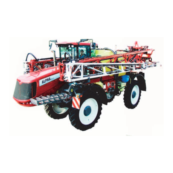
3 - Description General Info View 1. Tank lid 9. External engine controls 2. Main tank 10. Hand wash tank 3. Central frame 11. Cab ladder 4. External cleaning system 12. Working lights 5. Turbo Filler 13. Dipped beam lights 6. -
Page 38: Identification Plate
ATTENTION! The identification plate is regulatory, it should always be in place on the sprayer. For all information about the machine, please quote the serial number of the sprayer. An identification plate indicating data for the sprayer is mounted in the HARDI-EVRARD 62990 BEAURAINVILLE steel frame near the front of the sprayer on the right-hand side. -
Page 39: Data
3 - Description Data HARDI-EVRARD 62990 BEAURAINVILLE Marque N° de serie - 1 - Type-Variante Version - 2 - Année fabrication - 3 - - 7 - Masse maximale admissibles PTAC - 8 - Essieu1 / attelage PTRA - 4 -... -
Page 40: Sprayer Use
3 - Description Sprayer Use The HARDI sprayer is for the application of crop protection chemicals and liquid fertilizers. The equipment must only be used for this purpose. It is not allowed to use the sprayer for any other purposes. -
Page 41: Lifetime
To obtain this successfully, these instructions should be followed: • All service and maintenance work must be completed in due time • Repair any damages parts as quickly as possible • Replace or change spare parts as instructed • Only use original HARDI spare parts. -
Page 42: Liquid System
3 - Description Liquid System Pump The design of the diaphragm pump is simple, with easily accessible diaphragms and valves, which ensures that liquid does not contact the vital parts of the pump. Pump model 464/10 or 464/12 Valves and Symbols The possible functions of valves are distinguished by coloured identification on the function labels. - Page 43 3 - Description External cleaning (White symbol The valve is used for cleaning the outside of the sprayer...
-
Page 44: Dynamicfluid4 Pressure Regulation
3 - Description DynamicFluid4 Pressure Regulation Traditional fluid regulation starts, when the nozzles are opened. With DynamicFluid4 (DF4), the regulation is a continuous process, even if the nozzles are closed. A synthetic or ceramic disc and a stainless steel disc regulate the pressure and ensure quick reaction and zero leakages. - Page 45 3 - Description Regulation valve function diagram Spray job begins Start condition: μ Controller is turned OFF. Pump is turned OFF. ATTENTION! Auto mode icons shown, but could be Manual or Increment steps icons, depending on driver selection. Pressure SmartValve to Pressure draining/TurboFiller, suction SmartValve to Main tank, have water in Main tank.
-
Page 46: Filters
3 - Description Filters Filters on your sprayer are there to protect the components and prevent nozzle blockage. An Easy Clean suction filter is fitted in the working zone. A Cyclone pressure filter is fitted on the sprayer’s right side just in front of the hose reel, hidden behind the right front cover. It has a built-in self-cleaning function. - Page 47 3 - Description Cyclone Filter With the CycloneFilter, any impurities in the spray liquid will be cleaned out and returned to the main tank via the return flow. Function diagram: 1. Filter lid 2. Piping from pump 3. Piping to boom 4.
- Page 48 3 - Description TurboFiller The TurboFiller is where you add the chemicals to be mixed with water in the main tank. Capacity: approximately 35 litres. By operating the valves (A) on the side and valve (B) of the TurboFiller (C), you can do the following: •...
- Page 49 3 - Description Clean water Tank A clean water tank is located on the left side of the sprayer The water in this tank is for hand washing with clean water from the tap Capacity: approximately 15 litres.
- Page 50 3 - Description BoomPrime BoomPrime is a low pressure circulation system, which primes the spray boom tubes prior to spraying, ensuring a homogeneous fluid in the boom tubes and in the main tank. Below the illustration shows the BoomPrime system for the boom.
-
Page 51: Diagram - Liquid System With Optional Extras
3 - Description Diagram - Liquid system with optional extras 1. Suction SmartValve 23. Drain valve 2. Pressure SmartValve 24. Sprayer boom 3. Agitation/Cleaning valve 25. Flowmeter 4. Chemical container cleaning valve 26. Bypass valve 5. TurboDeflector ON/OFF valve 27. Sensor for pressure gauge 6. -
Page 52: Diagram - Intelligent Liquid System With Optional Extras
3 - Description Diagram - Intelligent liquid system with optional extras 1. Suction SmartValve 25. Flowmeter 2. Pressure SmartValve 26. Distribution valves 3. Agitation/Cleaning valve 27. Sensor for pressure gauge 4. Chemical container cleaning valve 28. Suction In-line filter 5. TurboDeflector ON/OFF valve 29. -
Page 53: Twin Air Technique
3 - Description TWIN Air technique General info With TWIN air assistance energy is added to the spray droplets to improve control with the spray liquid. The main purpose of the TWIN angling system is to counteract for the negative influence which wind direction and driving speed have on the quality of the spray job. -
Page 54: Boom
3 - Description Boom Standard Boom Features • Individual tilt of boom wings. (HAZ boom type only) • Each boom wing is 2-folded. • Alternative boom width: The boom may be used in 1/2-folded boom width. • Spring-loaded breakaway section. •... - Page 55 3 - Description Available Working Widths - Aluminium Full working width 1/2-folded width Type (meters) (meters) Available Working Widths - TWIN Force Full working width Type (meters) Force TWIN Force Force TWIN Force Force TWIN Force Force TWIN Force Force TWIN Force 3.1 Force TWIN Force 3.1...
-
Page 56: Engine
3 - Description Engine Rating plates of engine and after-treatment gas system The type (A), serial number (B), and technical data are stamped on the rating plate 1. Rating plate of the diesel particle filter 2. Rating plate of the SCR catalyst For all information, please provide the type and the engine serial number Exhaust gas after-treatment... - Page 57 3 - Description Diesel particles filter The combustion of diesel fuel results in soot, which is separated in the diesel particle filter. This must be regenerated as the contamination with soot increases. That means that the soot in the diesel particle filter is burned. The regeneration is based on a continuous regeneration process, which is activated as soon as the exhaust temperature of 250 °C is exceeded at the inlet of the exhaust gas after-treatment system.
-
Page 58: Cabin
3 - Description Cabin Description 1. Filter air inlet 2. Adjustable air vent 3. Air circulation for demisting 4. Air recirculation gratings Catégorie 4 conforme à l’EN 15695:2010 Caté Category 4 according to EN 15695:2010 Cate In compliance with Standard EN 15695, the cab is equipped with: •... -
Page 59: Description Of Driver's Seat
3 - Description Description of driver's seat ALPHA Evo EcoDrive is fitted with high quality professional seats. A user guide for the seat is supplied separately. You should read it in full before using the vehicle for the first time, and comply with the safety instructions on how the seat operates. 1. -
Page 60: Control Panel
3 - Description Control Panel 1. Gangway control switch 11. 4-Wheel steering switch 2. On-off switch of the spray pump 12. Clutch spraying pump switch. 3. Electronic Traction Control (option) 13. Engine RPM control switch. 4. Boom hydraulic function 14. Multi-functional grip. 5. -
Page 61: General Description Of Operator's Seat
3 - Description General description of operator's seat 1. 4-wheel drive control pedal 6. Multi-function display 2. Adjustable steering column 7. Side console 3. Brake pedal 8. Refrigerated lunch box 4. Throttle pedal 9. Adjustable driver's seat 5. HC9500 ISOBUS console 10. -
Page 62: Cabin Ceiling Controls
3 - Description Cabin ceiling controls HI HI 1. 2-position windscreen wiper switch (permanent, 9. Not used. intermittent) switch 10. Temperature sensor. 2. Windscreen washer switch. 11. Wing mirror adjustment switch. 3. Front working headlights switch. 12. Air conditioning control unit. 4. -
Page 63: 4-Wheels Steering (Standard)
3 - Description 4-Wheels Steering (standard) 1. Green indicator - Rear wheels aligned. 2. Blue indicator - 4-wheels engaged. 3. Green indicator - Front wheels aligned. 4. Automatic/ Manual mode Steering column Description 1. Wheel steering move up or down handle 2. -
Page 64: Aluminium Hydraulic Controls
3 - Description Lights controls Aluminium Hydraulic controls Inner wings simultaneously controlled . 1. Not used 2. Right and left extensions. 3. Left outer section 4. Folding left and right inner sections. 5. Right outer section. 6. Not used. Inner and outer wings simultaneously controlled 1. -
Page 65: Haz Boom Hydraulic Function Controls
3 - Description Inner and outer wings independently controlled 1. Not used. 2. Not used. 3. Folding left outer sections. 4. Folding left inner sections. 5. Folding right inner sections. 6. Folding right outer sections HAZ boom hydraulic function controls This configuration relates to sprayers equipped with the HAZ central frame with simultaneous control of the inner and outer sections. - Page 66 3 - Description AutoSlant When the AutoSlant function is installed, sensors placed on the boom are used to adjust the main slant angle of the boom relative to the terrain. To spray efficiently on hilly terrain, it is important to adjust the boom to be parallel to the terrain. AutoTerrain When the AutoTerrain function is installed, sensors placed on the boom are used to adjust the angle of each boom side relative to the terrain.
-
Page 67: Multi-Function Display
3 - Description Multi-function display General info The multifunction display manages the data for the engine and the hydraulic transmission of the self-propelled, such tachometer, engine temperature, hydraulic pressure, fuel level, etc...). It also allows you to select operating modes (speed limits, traction control, etc..), and alarms related to the engine and hydraulic transmission. -
Page 68: Transmission
3 - Description Transmission Diff-Lock differential locking front/back General Info The Diff-Lock system is only suitable on ALPHA Evo EcoDrive versions 40 or 50 km/h. The controller drive a hydraulic valve ’’ located between the front and rear hydraulic circuit. When the valve is controlled, the hydraulic circuit of each pump becomes independent. -
Page 69: Pneumatic System
3 - Description Pneumatic system Pneumatic diagram (with optional equipment) 28013001 V=20L AVT G 28073701 28044501 H=400 H=210 Ø0.8 1. Air compressor 10. Levelling valve 2. Main air tank 11. Front suspension airbag 3. No-return valve 12. Rear suspension airbag 4. - Page 70 3 - Description...
-
Page 71: Sprayer Setup
4 - Sprayer Setup Cabin Recommendations before installing the filter • Read carefully this instruction book before proceeding. Keep this instructions for retain consultation, • Before taking in place the filter, check the packaging is not damaging. Do not install a filter if the cardboard is rugged. •... -
Page 72: Unloading The Sprayer From The Truck
Manuel d’utilisation 67786201-100 - Version 1.00 F - 07.2011 3. Multi-jet spray 4. ISO nozzle disc www.hardi-fr.com www.hardi-fr.com 5. Table of ISO nozzle flow rates 6. Drain plugs (rinse tank-hand wash tank-storage box) 7. Graduated pot 8. Hydraulic pump lever (brake release - open the bonnet) 9. -
Page 73: Precautions Before Putting The Sprayer Into Operation
4 - Sprayer Setup Precautions before putting the sprayer into operation Your sprayer is protected by a resistant lacquer coat. However, we recommend regular application of a layer of anti-corrosion lubricant on all metal parts to avoid plant protection chemicals and fertilisers damaging the paintwork. If this is done before the sprayer is put into operation for the first time, it will be easier to clean the sprayer and keep the paintwork clean for many years. -
Page 74: Spraying
4 - Sprayer Setup Spraying Spraying pump • Screw the plug (1) (if necessary) in the 464 pump. Fitting the nozzles Install appropriate nozzles to achieve optimum spray quality • Place the nozzle filter (1) in the nozzle nut (2) •... -
Page 75: Boomprime Adjustment
4 - Sprayer Setup € DANGER! Never open the Cyclone filter unless the top green pressure manifold valve and bottom black suction manifold valve are both the suction valve is turned to the unused position, and the pressure valve is set to “main tank” turned to the unused position). -
Page 76: Chassis
4 - Sprayer Setup Chassis Altering the track width Track width (m) for ground clearance 1.20 m 480/80R42 520/85R38 300/95R52 340/85R48 380/90R46 420/80/ R46 650/65R38 480/80R46 520/85R42 Rim offset +125 +100 Axle type 1.76 2.00 1.82 2.05 1.91 2.14 1.97 2.20 2.06 2.29... -
Page 77: Tyres Inflate Pressure
4 - Sprayer Setup Procedure for Altering the track width The track width of the sprayer can be altered by sliding the axle according to the table above: • Loosen bolts (1) and clamping screws (2) • Measure the current track width (centre of right tyre to centre of left tyre). Each side must be extended or retracted half the desired alteration. - Page 78 4 - Sprayer Setup...
-
Page 79: Operation
5 - Operation Driving Starting up and shutting down the engine ÷ NOTE! Before starting up the engine, check the level of the engine oil, coolant, fuel and hydraulic oil. Starting up • Turn on the battery switch to «CONTACT» position •... -
Page 80: Travelling And Braking
5 - Operation μ If errors messages appears on the display and an audible alarm sounds, you must stop the engine immediate μ Always start up engine before starting up HC9500 controller Shutting down • Place the grip to neutral position to stop the machine. •... -
Page 81: Parking Brake
5 - Operation Parking brake The parking brake is used to keep the machine at a standstill. It acts on discs incorporated into the front and rear hydraulic motors. The brakes are activated when the hydraulic pressure reaches zero.: Engage the parking brake •... -
Page 82: Steering - Automatic 4-Wheel Steering Version (Standard)
5 - Operation Steering - automatic 4-wheel steering version (standard) General information The automatic 4-wheel steering is made up of two position sensors fitted on the front and rear rods, a 4-wheel steering activation pedal, a switch and indicators on the control panel. 1. -
Page 83: Driving In 4-Wheel Steering
5 - Operation Driving in 4-wheel steering In this mode, the front and rear wheels turn in opposite directions • Press on the switch to activate [AUTO] mode • Press the pedal and turn the steering wheel until the front wheels are in a straight line. -
Page 84: Steering - Automatic 4-Ws
5 - Operation Steering - Automatic 4-WS Genral info The 4-wheel steering system with crab steering is made up of potentiometers placed on the front and rear axle, a pedal in relation with the selector mode and the grip. Operation When the machine is started, the 4-WS system is operational. -
Page 85: Follower' Mode
5 - Operation ’Follower’ Mode In this mode, the front and rear wheels steer in the opposite direction, so that the rear wheels pass through the traces of the front wheels. For maximum accuracy, the system takes into account the distance between the axles (wheelbase) and the speed of the machine. -
Page 86: Manual Mode
5 - Operation Operation in ’Road’ 1. Select 4-Wheels Steering mode 2. Select «Road» mode 3. Push the grip towards to move the machine 4. Press and hold the pedal to engage the ’Steering Axle’ mode • Release the pedal to return to 2-Wheel Steering μ... -
Page 87: Slope Counter-Steering Function
5 - Operation Slope counter-steering function When you activate the 'slope counter-steering' function you can offset the track of the trailer device to the left or right. The direction in which the track is offset depends if the slope climbs or falls to the left or right of the machine. The aim of the 'slope counter-steering' function is to avoid the sprayer driving obliquely to the direction of work on a slope. -
Page 88: Hydraulic Track Adjustment (Optional)
5 - Operation Hydraulic Track Adjustment (optional) HTA control unit display 1. Forward Speed status. 2. Scrolling numbers (0 to 9). 2.20 3. Retracting Track button. 4. Valid button. 5. Extending Track button 6. Moving the cursor. 7. Status indicator. 8. - Page 89 5 - Operation Defects in the operation Defects in the operation may be caused by: • A forward speed out of the required speed range, while changing the track. • One or more wheels have not reached their position after 30 seconds (rut, mechanical, hydraulic or electronic defaults). In these cases, the status indicator (1) flashes.
-
Page 90: Transmission And Engine Operation
5 - Operation Transmission and engine operation General info This chapter describes how to use the control terminal for transmission and engine management Information messages • Press on button to scroll the following messages Engine overheating Oil engine pressure 0 to 100%. Battery voltage Turbocharger pressure 1300... -
Page 91: Settings Driving Mode
5 - Operation Settings driving mode • Press on button to scroll the messages: Speed limitation in «Field» mode, «Uphill», Speed limitation in «Road» mode, «Downhill» 38.0 km/h Engine RPM limitation Electronic Traction Control (SAPE) disengaged 1800 Drive mode «NORMAL» Electronic Traction Control (SAPE) engaged Drive mode «POWER»... -
Page 92: Automotive Mode
5 - Operation Change between Field, Uphill, downhill mode The change from one mode to the other Field mode can be achieved while driving Change from Field, Uphill, downhill to Road mode 1. Turn the speed selector to Road mode, the status appear in orange. -
Page 93: Comfort, Normal, Power Mode
5 - Operation How to change the control of the advancement The control of advancement can be controlled by either the grip or by the throttle pedal. Changing the control mode is only possible when the machine is stopped • Place the grip to the neutral position •... -
Page 94: Ecodrive Mode
5 - Operation Select Drive Mode • Press on button to display the menu • Press on button again to navigate to the drive mode menu • Press on buttons to select the required mode • Press on button to valid Status Normal Mode Comfort Mode... -
Page 95: Limitation Of Travel Speed In Automotive Mode
5 - Operation Enable / disable the speed limiter • Press on button and navigate to display the menu • Press on button and navigate to select speed limiter menu • Press on button to enable or disable the speed limiter km/h km/h Speed limiter disabled... -
Page 96: Engine R.p.m. Limitation
5 - Operation Set-point of speed limitation • Enable the speed limiter function • Press on to change the value km/h • Press on to valid the set-point value • Push fully toward the grip to travel at the selected speed Engine R.P.M. -
Page 97: Inter-Axle Differential Lock (Difflock)
5 - Operation Inter-axle Differential Lock (DiffLock) The DiffLock system can be only engaged in Field, Uphill, Downhill modes and automatically disengages when Automotive or parking brake is selected ÷ The DiffLock system is automatically disengaged when travel speed is beyond 20 kph. •... - Page 98 5 - Operation A warning message appears when the AdBlue level drops below 15%. The AdBlue filling must be completed as soon as possible. If this is not the case, several stages of alert will appear that can go as far as the reduction of engine performance. Message AdBlue Level (%) Performances moteur...
-
Page 99: Operation Monitoring
5 - Operation Operation monitoring Electronic engine control The status are displayed by the error lamp. The system monitors the condition of the engine and itself. • Function test - Ignition on, error lamp lights up for approx. 2 seconds and then goes out - Check the error lamp if there is no reaction after switching on the ignition. -
Page 100: Error Messages
5 - Operation Error messages When an operating anomaly occurs, an error message is displayed accompanied by a beep sounds continuously. If the message reads «STOP» the engine must be stopped immediately and the checks carried out. The message and beep can be cancelled by pressing buttons (2) and (3) for 2 seconds. If the fault has not disappeared the message will reappear after 30 seconds and the beep will sound after 15 minutes. -
Page 101: Severity Of Engine Defects
5 - Operation Severity of engine defects The messages and the associated warning lamp indicates the severity level of engine faults Messages Engine warning lamp Note Severity step 1 Minor event Severity step 2 Reduction performance Severity step 3 Flashes STOP STOP IMMEDIATELY THE ENGINE The DTC (Diagnostic Trouble Code) message indicates the number of errors on the motor:... -
Page 102: Implementation Of The Standstill Regeneration
5 - Operation Standstill regeneration ± Temperatures of approx. 600 °C occur on the exhaust pipe during regeneration. A special engine operating state becomes active during standstill regeneration and the machine is not allowed to be used during the active standstill regeneration. -
Page 103: Engine Anti-Stall
5 - Operation Regeneration messages Messages Warning lamp Power reduction Note Normal Operation Engine Warning lamp is off Engine Warning lamp is off Support mode Engine Warning lamp is off Standstill regeneration required Approval by the operator required Engine Warning lamp is on Standstill regeneration required Approval by the operator required Stage 1... -
Page 104: Hydraulic Oil Too Low
5 - Operation Hydraulic oil too low This message appears when the hydraulic oil level is too low. This requires an immediate shutdown of the machine. μ A too low level of hydraulic oil can lead to overheating the hydraulic system or damage the transmission •... - Page 105 5 - Operation Gangway manual control ÷ NOTE! The retractable gangway automatically moves away when the engine is shut down. If the machine is fitted with a LPA5 central frame, it may in case of electrical or hydraulic failure, the retractable gangway does not deviate from the cab.
-
Page 106: Cabin
5 - Operation Cabin Suspension of the cab (If fitted) The suspension of the cabin is pneumatic with 2 dampers placed between the chassis and the floor of the cabin. An air presssure regulator maintains a constant pressure into the pneumatic dampers. Setting the correct regulator pressure is essential for optimizing the suspension and comfort in the cabin. - Page 107 5 - Operation Automatic mode When the speed blower knob is on AUTO, in this case: 1. Heating valve is automatically controlled, depending of: • Set-point temperature • Ambient temperature • Outside temperature 2. Speed blower is automatically controlled depending of: •...
- Page 108 5 - Operation Speed blower Pushbutton Screen Descriptions knob position Automatic mode AC ON - heating valve is automatically controlled - Speed blower is automatically controlled - A/C compressor is automatically controlled AC ON Automatic mode with manual speed control - heating valve is automatically controlled - Speed blower controlled manually Automatic mode with A/C compressor...
-
Page 109: Pressurization Operating Mode
5 - Operation The screen displays «LO» and «A/C on». HI mode When the temperature control knob switch is in «HI» position, the ATC control module forces the system as follows: • Water valve is opened • Speed blower at ¾ of Max (if the selector knob is on «AUTO» •... -
Page 110: Default Codes
5 - Operation The flap fresh air is open. Function Depressurization cabin LED When overpressure button is «ON», after 30 seconds a pressure switch gives information of measure of the difference between inside and outside pressure of the cabin. If the cabin: - is pressurized the led is ON - isn’t pressurized the led is f lashing at 1Hz frequency. -
Page 111: General Info
• Spraying speed. Sprayer Use The HARDI sprayer is for the application of crop protection chemicals and liquid fertilizers. The equipment must only be used for this purpose. If the sprayer is to be used for any other purposes than the ones described in this instruction book, a new risk assessment and a workplace assessment must be completed for this use. - Page 112 The labels must be readable when operating the sprayer. Damaged or unreadable labels must be replaced. The symbols are explained here. Symbol on label Symbol description Label color HARDI item number Suction from main tank Black / Blue 97809900 Suction from Rinse Tank...
- Page 113 Unintended boom movements may cause contact with overhead power lines, causing a risk of fatal accidents. μ ATTENTION! A label (HARDI item no. 978448) follows the sprayer. This label must be placed in the cabin visible from the operator’s seat.
-
Page 114: Manoeuvring Of The Boom
5 - Operation Manoeuvring of the Boom Applicable for HC 6500 / HC 8600 / HC 9600 / ISOBUS. ÷ WARNING! The folding functions must only be operated, when the sprayer is stationary! Failure to do so will damage the boom. How To Unfold the Boom 1. - Page 115 5 - Operation Liquid System General Info Please refer to the Spray Technique book for instructions on the use of filters, nozzles etc., and their combination in use with specific spraying applications. Quick Reference - Operation In the following diagram, the handle positions for different options are described.
-
Page 116: Filling/Washing Location Requirements
ATTENTION! Legislation and requirements vary from country to country. Always follow local legislation in force. μ ATTENTION! It is the responsibility of the sprayer owner/operator to comply with all relevant legislation. HARDI cannot undertake any responsibilities for incorrect operation and use. -
Page 117: Filling Through Tank Lid
5 - Operation Filling Through Tank Lid The tank lid is provided with a hinge (1) so it can be lifted. A locking system (2) prevents it from being opened. Opening: • Unlock and turn the lid anticlockwise then lift. Closing: •... -
Page 118: External Filling Device
5 - Operation External Filling Device The External Filling Device is operated as follows: 1. Remove cover and connect suction hose to the suction manifold. 2. Turn pressure Smartvalve to ’’Main tank’’’ 3. Turn handle on External Filling Device valve towards Filling Device 4. -
Page 119: Filling Of Clean Water Tank
5 - Operation Filling of Clean water tank To fill the clean water tank: 1. Remove the screw cap 2. Fill with clean water 3. Refit the screw cap Volume 15 litres For use of clean water The water from this tank is for hand washing, cleaning of clogged nozzles etc. This water never not to be used as drinking •... - Page 120 5 - Operation Safety Precautions - Crop Protection Chemicals Always be careful when working with crop protection chemicals! ± WARNING! Always wear proper protective clothing before handling chemicals! Personal protection Depending on chemical type, protective gear/equipment should be worn to avoid contact with the chemicals, such as: •...
-
Page 121: Operating The Turbofiller
5 - Operation Operating the TurboFiller The TurboFiller is where you add the chemicals to be mixed with water in the main tank. Capacity: approximately 35 litres. Before Use • raise the handle (A) to unlock the position of the TurboFiller. •... - Page 122 5 - Operation TurboFiller Suction Valve The valve is used simultaneously with the TurboFiller. The valve has 2 settings: Continuously open or spring-loaded normally closed. Open the valve by lifting the lever up, when chemicals are to be filled into the TurboFiller and transferred to main tank. TurboDeflector Valve This TurboDeflector valve activates the vortex flushing of the TurboFiller.
- Page 123 5 - Operation Filling Liquid Chemicals Using the TurboFiller μ ATTENTION! We advice to use the TurboFiller, when you fill chemicals on the sprayer. 1. Fill the main tank at least 1/3 with water (unless otherwise stated on the chemical container label). 2.
-
Page 124: Filling Powder Chemicals Using The Turbofiller
5 - Operation 9. Turn the agitation valve towards “agitation”. μ ATTENTION! If foaming is a problem, turn down the agitation. 10. When the spray liquid is well agitated, turn handle of the pressure SmartValve towards “spraying” position. The agitation continues during spraying of the crop. -
Page 125: Turbofiller Rinsing
5 - Operation 7. Flush the TurboFiller with clean water from the rinsing tank or from an external tank by shifting to suction. The TurboFiller suction valve must be open for at least 20 seconds after the rinse water is no longer visible in the hopper, in order to completely empty the transfer hoses into the main tank. -
Page 126: Boomprime
5 - Operation 2. Simultaneously press the Chemical Container Cleaning lever and the TurboFiller suction valve. This rinses the chemical container with the flushing nozzle, while the rinsing liquid is emptied out of the TurboFiller. TurboFiller rinsing - TurboFiller lid is closed 1. -
Page 127: Before Returning To Refill The Sprayer
NOTE! Find the density for your liquid fertilizer on the packaging or on the material safety data sheet (MSDS) included. Additional Information See the other book delivered from HARDI - Spray Technique - to get further information about: • Calibration of the sprayer... -
Page 128: Operating Limits
ATTENTION! It is recommended not to drive faster than 16 km/h when spraying. μ ATTENTION! The pressure range for the nozzles are 1.5 - 5 bar (except for HARDI INJET nozzles, which are ranging from 3-8 bar). The spraying pressure should be within these limits. - Page 129 5 - Operation μ ATTENTION! In the table below, the specified combination of nozzle size and sprayer setup is not suitable, as the full pressure range of 5 bar for the nozzle cannot be reached, when spraying the maximum volume rate (l/ha) on the crop. This is due to the nozzle design.
-
Page 130: Cleaning
For the best result, use a cleaning agent recommended by HARDI, e.g. AllClearExtra. • It is sometimes necessary to leave spray liquid in the tank for short periods, e.g. overnight, or until the weather becomes suitable for spraying again. -
Page 131: Quick Reference - Cleaning
5 - Operation Quick Reference - Cleaning 4 x 1/6 4 x 1/6 μ ATTENTION! Pump speed 250-280 r.p.m.. A. Full agitation. B. Wait 3 seconds before changing valve position. C. Minimum 45 seconds with nozzles OFF. D. Spray until comes out nozzles E. - Page 132 5 - Operation Standard Cleaning μ ATTENTION! For cleaning between spray jobs, where crops are not very sensitive towards chemicals just sprayed. 1. Engage the pump with engine in idle, so that pump speed is as low as possible (approx. 250/550 rpm, depending on pump type).
-
Page 133: Cleaning The Tank And Liquid System
5 - Operation Cleaning the Tank and Liquid System μ ATTENTION! Thorough cleaning of the sprayer is to be carried out when shifting to crops, which are very sensitive to chemicals just sprayed, or prior to storage for a longer period of time. ÷... -
Page 134: Use Of Rinsing Tank And Rinsing Nozzles
5 - Operation Use of Rinsing Tank and Rinsing Nozzles The integrated rinsing tank can be used for three different purposes: A. Full internal rinsing or cleaning. In-field diluting before cleaning. B. Rinsing spray circuit without diluting main tank content. Rinsing when main tank is not empty. C. - Page 135 5 - Operation 11. Shut off all nozzles by the main ON/OFF button. 12. Now turn the suction SmartValve towards “Rinsing tank” and the pressure SmartValve on “Tank rinsing”. 13. Use another 1/6 (approximately 75 l) for this. The tank strainer should be removed to avoid shading the rinsing nozzle. 14.
- Page 136 5 - Operation 1. Engage pump at approximately 300 r.p.m. 2. Turn suction SmartValve towards “Rinsing tank” and pressure SmartValve towards “Internal Tank Rinsing”. € DANGER! Before turning Pressure SmartValve to “Pressure draining/TurboFiller” it is very important to be sure that the quick coupler lid is correct and completely mounted to the filling stud into its locked position.
-
Page 137: Full Internal Cleaning (Soak Wash)
5 - Operation Full Internal Cleaning (Soak Wash) μ ATTENTION! This cleaning procedure is always used, if one or more of these situations occur: A. The next crop to be sprayed is at risk of being damaged by the chemical just used B. -
Page 138: Primeflow - Manual Cleaning
WARNING! It is the responsibility of the sprayer operator or owner, that the sprayer is cleaned sufficiently to prevent contamination of the environment, crop damages and health and safety hazards to the operator and the public. HARDI cannot be held responsible for any damages or incidents related to insufficient cleaning. μ... -
Page 139: Pressure Draining
5 - Operation Pressure Draining It is possible to drain to an external tank. This is done the following way: 1. Connect a hose from an external tank to the quick coupler on the sprayer. 2. Turn the Pressure SmartValve towards 3. - Page 140 5 - Operation...
-
Page 141: Maintenance
6 - Maintenance Lubrication General information Always store lubricants in a clean, dry and cool place - preferably at a constant temperature. Keep the containers and funnels. Clean lubrication points before applying the lubricants. Always follow the recommendations concerning quantity. If no recommended quantity is given, feed lubricator until new grease becomes visible. -
Page 142: Recommended Part List
6 - Maintenance Recommended part list The table below shows the filters used for the first maintenance of the sprayer First Components Filters Part number Quantity maintenance Oil Lub. filter 27012701 Fuel Pre-filter 27009001 Deutz engine - Tier 4 final Stage IV Fuel Filter 278793 AdBlue filter... -
Page 143: Service Intervals
6 - Maintenance Service intervals Interval +500 hours Hydraulic Hydraulic oil level Hydraulic oil (Every 500 hours or Every year) Check hydraulic filters clogged Hydraulic filters (Every 500 hours or Every year) Drain the hydraulic tank Cabin Windshield washer fluid level Air cabin filter - category 4 (Every 150 hours) Air conditioning gas... -
Page 144: Engine
6 - Maintenance Engine Lubricating oil level ÷ Low lubricating oil level and overfilling lead to engine damage. The lubricating oil level may only be checked with the engine in a horizontal position and switched off. If the engine is warm, switch off the engine and check the lubricating oil level after 5 minutes. -
Page 145: Engine Suction System
6 - Maintenance ÷ The excess of coolant is automatically eliminated through the outlet pipe μ ATTENTION! Only use the recommended coolant. Never mix with other coolants. If in doubt, drain the cooling circuit completely. Engine Suction System μ Do not work when the engine is running! ÷... -
Page 146: Fuel Pre-Filter Draining
6 - Maintenance Fuel Pre-filter Draining Empty water tank • Switch off the engine • Place suitable collecting containers underneath • Electrical connection - disconnect cable connections (4) • Loosen drain plug (5) • Drain fluid until pure diesel runs out •... -
Page 147: Engine Lubricating Oil
6 - Maintenance Engine Lubricating Oil Regulation for working on lubrication of oil ± Do not work when the engine is running! Smoking and naked lights prohibited! Be careful of hot lubricating oil. Danger of scalding! ÷ Pay attention to utmost cleanliness when working on the lubricating oil system. Clean the area around the components concerned carefully. -
Page 148: Adblue Filter Replacement
6 - Maintenance AdBlue Filter Replacement ± Protective gloves are to be worn when working with Selective Catalytic Reduction (SCR) components. Ensure cleanliness. Servicing • Switch off the engine. • Electrical connection – Disconnect cable connections. • Place suitable collecting containers underneath. •... -
Page 149: Battery
6 - Maintenance • Run engine up to operating temperature (opening temperature of the thermostat) allow to bleed the coolant circuit • Switch off the engine. • Check coolant level in cooled engine and top up to the MAX mark or filling level on the expansion tank if necessary. ÷... -
Page 150: Cabin And Air Conditioning
6 - Maintenance Cabin and air conditioning Replacement the cabin filter (category 4) Recommendation € Change the filter every 150 hours of use or at least once a year once the packaging is opened ± WARNING: Always wear protective clothing and gloves, before servicing •... -
Page 151: Air Conditioning Compressor
6 - Maintenance • Fit the filter in the correct direction of air flow taking into account the marking of the direction indication affixed to it. • Place the frame equipped with the filter in the housing • Screw completely the 4 screws (1). Air conditioning compressor The belt of compressor drive should be checked regularly. -
Page 152: Hydraulic
6 - Maintenance Hydraulic Hydraulic system Oil level • Top up the hydraulic tank until maximum level Hydraulic Filter Clogging Indicator Hydraulic suction filters are fitted with clogging indicators. ÷ NOTE! Reading the clogging indicator occurs when the hydraulic oil is at normal operating temperature. •... -
Page 153: Auxiliary Hydraulic Filters
6 - Maintenance • The spent element can be unscrewed from the cover by rotating it anticlockwise • Check seals for damage and replace if necessary • Clean the magnetic core by wiping it lengthwise with a cloth. • Screw the new filter element onto the cover at clockwise as far as 78626601 it will go, otherwise the tank bottom valve may be damaged 78626801... -
Page 154: Cleaning The Hydraulic Tank
6 - Maintenance Cleaning the hydraulic tank • Drain the hydraulic tank. Refer to the chapter: “Drain the hydraulic tank” on page 153 3000 • Loosen screws(2) and pull out the filter body • Thoroughly clean the tank • Reassembly the filter body, change the seals if necessary and use a new plug seal μ... -
Page 155: Chassis And Boom
6 - Maintenance Chassis and boom HTA Rear Axle Lubrication • Grease nipples points according to illustration HTA Front Axle Lubrication • Grease nipples points of the HTA according to the illustration... -
Page 156: Paralift Lubrication
6 - Maintenance Paralift Lubrication • Grease the paralift according to the illustration) LPA5 Central Frame Lubrication • Grease nipples of the central frame according to the illustration... -
Page 157: Tr4 Boom Lubrication
6 - Maintenance TR4 Boom Lubrication Bolts tightening • Make sure that all nuts and screws are properly tightened and tighten if necessary. (Use a wrench with a 1.00 m lever) Adjustment of Spring in Breakaway Section • Check the load of the spring. The Spring tension corresponds to its initial length plus 100 mm RHA Boom lubrication Bolts tightening •... -
Page 158: Tightening Lug Nuts
6 - Maintenance Spring Load for Breakaway Section • Check the load of the spring. The Spring tension corresponds to its initial length plus 100 mm TR4 Boom Lubricating • Lubricate all the hinges (8 points of lubrication) and all the ball joints and pin joints Tightening lug nuts •... -
Page 159: Spraying
6 - Maintenance Spraying Suction filter (if fitted) Servicing the filter • Turn the pressure SmartValve towards the unused function or to tank cleaning nozzles • Unscrew the body nut (1) • Clean the filter element (2) Reassemble • Grease the O-ring (3) on the body nut guide •... -
Page 160: In-Line Filter
6 - Maintenance 4. Place the filter/filter lid into the housing and screw the lid, until it hits the stop. ± WARNING! Always wear protective clothing and gloves, before servicing the filter! € DANGER! Both the suction valve andThe pressure SmartVvalve must always be closed turned to the unused function or to “tank cleaning nozzles”, before opening the CycloneFilter! If not, the spraying liquid can hit you, when opening the filter, and the main tank content will drain away! In-Line Filter... -
Page 161: Spraying Pressure Gauge
6 - Maintenance Spraying Pressure Gauge IThe pressure gauge may no longer display the pressure with sufficient accuracy. This may be due to clogging of the hose connecting it to the liquid system. In this case, you can dismantle the pressure gauge to rinse the hose. 1. -
Page 162: Compressed Air System
6 - Maintenance Compressed air system Draining air tanks ± ALERTE! Air tanks may contain a residual air pressure! 1. Front right air tank for suspension 3. Main air tank 2. Front left air tank for suspension 4. Rear air tank for suspension •... -
Page 163: Air Compressor
6 - Maintenance • Replenish oil whenever necessary the bowl without exceeded the maximum level. MAXI Oil flow rate adjustment • Adjustment by means of knob with ’’pull-turn-push’’ type locking system • Set oil flow rate during the passage of air. •... -
Page 164: Air Pressure Switch Adjustment
6 - Maintenance Air pressure switch adjustment To adjust the pressure in the circuit: • Turn le knob (1) on AUTO position • Loosen the screw (2) and remove the cover • Always adjust the cut-out first to set the operating point. The contacts will open on high pressure. -
Page 165: Occasional Maintenance
The operator must select appropriate intervals for the occasional maintenance. If in doubt, contact your local HARDI dealer. Lifting and Removing the Pump When lifting and removing the pump, use a shackle fitted to the built-in lifting eye located between the heads (A). - Page 166 Lubrication After Assembly After disassembling the pump (diaphragm renewal, etc.), the pump MUST be lubricated with 200 g grease into each lubrication point. HARDI pump grease cartridge (400g): HARDI item no. 28164600 Overhaul Kit Pump model: 464 Diaphragm pump overhaul kit (valves, seals, diaphragms etc.) can be ordered.
-
Page 167: Speed Sensor For Pump
6 - Maintenance Speed Sensor for pump The speed transducer, measuring rounds per minute (r.p.m.), is located at the inner side of the PTO shield. This sensor is an inductive type, which requires metallic protrusions to pass by it to trigger a signal. If the sensor is exchanged, it must installed accurately to function. -
Page 168: Feed Pipe Clamp Assembly
6 - Maintenance Feed Pipe Clamp Assembly A feed pipe can be removed from the pipe clamps the following way: 1. Use a flat bladed screwdriver to prize the cover off the first corner (A). 2. Hold the clamp top with your hand and prize off the opposite corner (B) with the screwdriver. - Page 169 6 - Maintenance In Case of Leaks 1. Disassemble the pipe fitting. 2. Check condition and position of O-ring. Replace it if damaged or cracked. 3. Clean and lubricate the O-ring. Lubricate all the way around using a non-mineral lubricant. 4.
- Page 170 6 - Maintenance Locking piece (B) and upper part separated (C). Inside the lower part (D), the O-ring (E) is located, and it can now be removed for maintenance. Note that the O-ring, when seated, is supposed to be a little out of shape to fit tightly around the hole in the nozzle pipe.
-
Page 171: Nozzle Pipe Assembly
6 - Maintenance Nozzle Pipe Assembly If leaks of fluid occur in the pipelines on the spray boom, it is necessary to check the gaskets. The pipe fittings need to be disassembled to locate the gaskets. Occasional maintenance of the gaskets and pipe assemblies is recommended. Poor sealing are usually caused by: •... -
Page 172: Boomprime One-Way Valve
6 - Maintenance Gasket Types Usually an O-ring is used, but there is also a different type of gasket in use (F). How To Remove Lock Ring If the lock ring needs to be replaced, this can be done by mounting a connector (A) in reverse direction. -
Page 173: Adjustment Of 3-Way Valve
6 - Maintenance Adjustment of 3-Way Valve The large ball valve used for SmartValves and valves for filling equipment (type s93) can be adjusted, if it is too tight to operate - or if it is too loose (= liquid leakage). •... -
Page 174: Haz Boom
6 - Maintenance HAZ Boom Readjustment of Boom - General Info Before commencing adjustment jobs, please go through this check list. 1. The sprayer must be well lubricated (see the section “Lubrication”). 2. Place the sprayer on level and solid ground. 3. -
Page 175: Adjustment Of Springs In Centre Section
6 - Maintenance Adjustment of Springs in Centre Section Description of Spring Function The adjustable spring arrangement in the centre section will level out abrupt movements of the spray boom. If different field conditions appear, for example hilly or sloping fields, the spring arrangement may need manual adjustment. -
Page 176: Adjustment Of Boom Tilt
6 - Maintenance Adjustment of Boom Tilt The unfolded spray boom must be horizontal to begin with, before you start a spray job. If needed, horizontal adjustment of the boom wings is possible when adjusting the ram eye on the hydraulic cylinder for tilt motion on both sides of the sprayer. -
Page 177: Horizontal Alignment Of Inner Sections
6 - Maintenance Horizontal Alignment of Inner Sections This alignment is to compensate for the wind resistance when driving with an unfolded boom, as well as keeping a good balance in the boom when driving on uneven fields. The boom is adjusted relatively to the direction of driving. Steps for adjustment: 1. - Page 178 6 - Maintenance Vertical Alignment of Middle and Outer Sections Steps for adjustment: 1. Start with the middle section, which is aligned with the inner section. 2. At the top of the boom, the nuts (A,B) are turned. Wrench = 41 mm. Raise the boom: Loosen (A), tighten (B).
- Page 179 6 - Maintenance Adjustment of Boom Lock Description of Boom Lock Mechanism To prevent accidental folding of the spray boom while spraying, the boom joints interlock automatically when fully unfolded. The conical bolt (A) will guide the boom sections into the interlocking position. A specially designed steel plate (B) will be lifted up, as the conical bolt (A) passes through the plate.
- Page 180 6 - Maintenance Vertical Alignment of Breakaway Section Align the breakaway with the outer section of the boom. Step for adjustment: 1. Loosen the nut (A). Wrench = 24 mm. 2. The hexagon (B) is turned. Wrench = 17 mm. Turn clockwise: The breakaway is raised.
-
Page 181: Adjustment Of Breakaway Section
6 - Maintenance Adjustment of Breakaway Section The breakaway section at the boom end will move back or forth, if it hits a stationary object, e.g. a pole or a tree, when driving with an unfolded spray boom. The spring on the outer section of the boom will pull the breakaway back into place, when the boom is clear of the object. -
Page 182: Alignment Of Rubber Pads On Spray Boom
Accumulator Service If the yaw damping seems to be insufficient, the accumulators needs to be recharged or replaced. Ask your HARDI dealer to assist you. 1. Check for any leaks. 2. Check pressure setting for the accumulators in the test sockets, which are located in the hydraulic block below. -
Page 183: Tr4 Boom
6 - Maintenance TR4 Boom ÷ Before starting adjustment of the boom, Tighten all the bolts at the hinge points before adjusting the boom 1. Unfold the boom and remove the bolts from the cylinder... - Page 184 6 - Maintenance 2. If the 1st arm and the 2nd arm are not horizontal alignment, turn the eye bolt A and B. When the boom is horizontal position, tighten slightly the counter nuts At the same time, pre-adjust the 2 stops (C) and (D) between the 1st and 2nd arms, so that the boom is perfectly aligned 3.
- Page 185 6 - Maintenance 4. If the 2nd section is too high, unfold the boom again, without disturbing the horizontal setting of either arm, adjust the two eye bolts A and B to move the 1st arm away from the 2nd arm. If the 2nd arm is too low, it is necessary to approach the 2nd arm 5.
- Page 186 6 - Maintenance When the boom is correctly aligned, firmly tighten the locknut on the stops (C) and (D) and eye bolts. Serrage contre-écrous Tighten counternuts Serrage des contre-écrous Tighten counternuts 11. Remove the hydraulic hoses and loosen screws (G) Fold the boom by hand so that the 2nd arm is in its bracket on the 1st arm.
-
Page 187: Off-Season Storage
6 - Maintenance Off-Season Storage General Info To preserve the sprayer intact and to protect its components, the following off-season storage program is carried out. Before Storage When the spraying season is over, you should devote some extra time to the sprayer. If chemical residues are left over in the sprayer for longer periods, it may reduce the life of its individual components. -
Page 188: After Storage
6 - Maintenance After Storage 1. After a storage period, the sprayer should be prepared for the next season the following way: 2. Adjust the tyre pressure 3. Wipe off the grease from hydraulic ram piston rods. 4. Fit the pressure gauges again. Seal with Teflon tape or similar. 5. -
Page 189: Repair
7 - Repair Operational problems General Info Operational incidents are often due to the same reasons: • A suction leakage reduces the pump pressure and may interrupt suction completely. • A clogged suction filter may damage suction or interrupt and prevent the pump from running normally. •... -
Page 190: Spraying
7 - Repair Spraying FAULT POSSIBLE CAUSES SOLUTION No spray from boom Air leak on suction line Check tightness of suction filter Check external hose connection Check diaphragm pump (diaphragms, valves, valve covers) Air being sucked into system Start the sprayer pump Suction/pressure filter clogged Clean the filters Lack of pressure... -
Page 191: Transmission
7 - Repair Transmission FAULT POSSIBLE CAUSES SOLUTION Vehicle does move forward Incorrect use Check that the parking brake is disengaged. Lever in neutral. Electronic failure Read the error code SD or DTC and contact technical support Check electrical circuits (connections, cables etc.) Hydraulic failure Check feed pressure of transmission pump (28 bar) Check operating pressure (max 450 bar) -
Page 192: Transmission Pump High Pressure Relief Valves
7 - Repair ÷ Do not continue to actuate the hand pump after the brakes have been fully released. Excessive pressure could damage the motor braking mechanism. After towing or before starting the machine again, always engage the parking brake by turning the valve handle to a horizontal potion and placing the safety bar (2) in position, as indicated in the picture ( A). -
Page 193: Errors Messages
7 - Repair Errors Messages Transmission errors When an operating error appears in the hydraulic transmission the an icon is displayed on the screen Table of SD error code Error Description Error Description Codes Codes Low battery voltage Low battery voltage 12V sensor low supply voltage 12V sensor high supply voltage 5V sensor low supply voltage... - Page 194 7 - Repair Error Description Error Description Codes Codes CAN bus error- from SmartDrive Auto ’’slave’ . Missing signal SD SAPE : checksum parameter error Speed sensor error (overspeed SD SAPE : Min/Max parameter error Supply voltage error between the machine ans software SD SAPE : Front left speed sensor erro SD SAPE : Front left speed sensor error SD SAPE : Rear left valve error...
-
Page 195: Engine Errors Codes
7 - Repair Engine Errors Codes When an operating fault appears, the error code is displayed on the screen • Press the button (1) and navigate until the DTC menu appear An icon indicates the number of errors. • Press the button (2) to display the SPN and FMI error code of the engine... -
Page 196: Engine Codes Errors
7 - Repair Engine codes errors Component / Location Description (Error location) Hand throttle Cable break or short circuit, signal implausible compared to signal or ilde sensor 2 ,3, 4, 11 Vehicle speed signal Speed above target range, signal missing or implausible 0, 8, 12, 14 Accelerator pedal Cable break or short circuit, signal implausible compared to signal of idle sensor... - Page 197 7 - Repair Component / Location Description (Error location) Single injector Short circuit (injector 1) 3, 4, 11, 13 Single injector Cable break (injector 1) 5, 13 Single injector Short circuit (injector 2) 3, 4, 11, 13 Single injector Cable break (injector 2) 5, 13 Single injector Short circuit (injector 3)
- Page 198 7 - Repair Component / Location Description (Error location) 1322 Multiple cylinders Misfire detected 11,12 1323 Single cylinder Misfire detected (cylinder 1) 11, 12 1324 Single cylinder Misfire detected (cylinder 2) 11, 12 1325 Single cylinder Misfire detected (cylinder 3) 11, 12 1326 Single cylinder...
- Page 199 7 - Repair Component / Location Description (Error location) 523550 Terminal 50 Engine start switch hangs 11, 12 523550 ECU internal error Time processing unit (TPU) defective 2, 11 523561 Begin of injection period Outside target range or missing (cylinder 1) 523562 Begin of injection period Outside target range or missing (cylinder 2)
-
Page 200: Location Of Main Components
7 - Repair Location of main components The main control unit are located in the cab under the driver’seat. 1. Main circuit fuses and relays. 2. Retractable gangway control system. 3. 4-wheel drive control system (4RD version). 4. Flashing indicator unit. 5. - Page 201 7 - Repair Code Description Code Amp. (A) Description not used 15.A front side cabin lights 10 A side lights/backlighting 15 A starter contactor 12 V BAT - ceiling 10 A starter solenoid 15 A flasher unit - control 15 A dipped beam 15 A not used...
-
Page 202: Multifunction Display
7 - Repair Multifunction display To access to the diagnosis menu: • Press simultaneously during 3 sec the buttons (1) and (2) • Enter the password by pressing the buttons (1) and/or (4) : PASSWORD Password : 1 0 0 1 1 0 0 1 CAN O Engine CAN bus CAN_1 Smart Drive CAN bus... -
Page 203: Fuses Test
7 - Repair Fuses Test The PCB is equipped with «Autofuse» fuses (1) and «Maxifuse» fuse (2). • Take off the fuse to be tested and put it in the test fuse holder. If the indicator (4) light up, this means that the fuse is not blown. Engine and JobCom fuses This fuses are located at the left hand side of engine compartment N°... -
Page 204: Jobcom With Primeflow
7 - Repair JobCom with PrimeFlow The converter has two fuses: 1. 30AT F2 / 32V 2. 10AT F1 / 32V, Hardi P/N 26023500 JobCom connections 1. 10A blade fuses for TWIN actuators left and right Program I/O Extra FlexC Rpm... -
Page 205: Lightening
7 - Repair Lightening Highlights A. Replace the halogen lights bulb: μ ATTENTION! Before changing the bulb, make sure the unit is turned off and wait until the lamp is completely cooled if you do not want to burn yourself. •... -
Page 206: Hydraulic Track Axle
7 - Repair Hydraulic Track Axle Angular sensor faulty If an angular sensor is faulty, the red light (1) turns on . Calibrating the angular sensor stops After replacing an angular sensor, it is necessary to recalibrate the control unit, indicating the range of the sensor ÷... - Page 207 7 - Repair 4. Press the button (2) to scroll the first digit. 5. Press the button (6) to move the cursor to the 2nd digit . 6. Press the button (4), le message «U2» is displayed briefly, then signal from control unit is displayed 7.
-
Page 208: Cabin
7 - Repair Cabin Diagnostic Diagnostic mode The ATC will be provided with a diagnostic procedure in order to perform some checks on the control led devices. The ATC goes on diagnostic mode by pressing simultaneously the buttons (during power on of the ATC) with the blower speed knob in «OFF»... - Page 209 7 - Repair Inside temperature sensor control Press the button when is visualized the outside temperature on the display appear the value of the inside temperature The symbol is flashing when the inside temperature is visualized Anti-icing temperature sensor control Every time that the button is pressed, the anti-icing value temperature is visualized for 5 seconds The symbol...
- Page 210 7 - Repair Compressor control Every time that the button is pressed, the AC output change the state When the AC output is on, the «A/C» symbol is lit. ÷ The anti-icing function is disable Pressurization control Press the button, the auxiliary fan output change the state. When the symbol is on, the auxiliary fan is on.
-
Page 211: Technical Specifications
8 - Technical Specifications Characteristics Main Characteristics Tank size (litres) 5000 (+5%) Pumps 464-10 / 464-12 Boom ALUMINIUM TR4 / TR4R / RHA /RA/ FORCE/ TWIN FORCE Electronics (Spraying) HC9600 Engine 6 cylinder Deutz engine 180 KW Tier 4 final - Stage IV Transmission 2 Sauer Pumps H1 (2x115 cc) on 40 kph Suspension... -
Page 212: Weight
8 - Technical Specifications Weight Empty weight Basic vehicle weight. It may vary depending on the equipment and options Variant 401MA 402MA 401HA 402HA 401MB 402MB 401HB 402HB Total 10850 11380 11350 11880 Axle 1 6720 6810 6970 7060 Axle 2 4130 4570 4380... -
Page 213: Accumulator
8 - Technical Specifications Other tyres ÷ NOTE! When replacing tires, check that the new tires have the correct load index. ÷ Other optional tyres are possible, provided that the static loaded radius and the load index are in accordance with the table below at a speed of 40 kph, resulting in no change in track and / or width of the vehicle. -
Page 214: Identification Plates
8 - Technical Specifications Identification plates Cabin An identification plate is fitted below the driver’s seat. Transmission pump An identification plate is fitted on the pump Deutz engine An identification plate is fitted on the engine Hydraulic motor An identification plate is fitted on the motor MS18- F -A21 - R18 - A520 - 78DMF A47911C Code :... - Page 215 8 - Technical Specifications Transmission Controller SD-EASY EXTENDED plate To request information, note the Code (1) and the Num (2) SD-EASY-EXTENDED A42959U Code Serie 1341 005121 Transmission Controller SD-AUTO plate To request information, note the Code (1) and the Num (2) EXTENDED A22383E Code...
-
Page 216: Cabin
8 - Technical Specifications Cabin Air conditioning diagram ATC 273F60... -
Page 217: Air Conditioning Diagram
8 - Technical Specifications Air Conditioning Diagram Moteur volet de recyclage... - Page 218 8 - Technical Specifications...
- Page 219 Index Index EasyClean Filter, 46 Symbols Electrical System, 31 «CRAB» Mode, 87 Engine radiators, 144 Environmental Numerics Precautions, 33 2-wheel steering, 82 Protection, 26 464-12 Pump, 214 Errors Messages, 193 4-wheel steering, 82 External Filling Device, 118 Accessories, 72 Feed Pipe Snap-Lock, 168 Accumulator, 213 Filling Agitation, 125...
- Page 220 Index Nozzle Holder Assembly, 168 Service Work Precautions, 34 Nozzle Pipe Slope counter-steering, 87 Assembly, 171 Soak Wash, 137 Connector, 169, 171 Sound Level, 213 Lock ring, 171 Spare Parts O-ring, 169, 171 Wear Parts and Aids, 25 Nozzles, fitting the, 74 Spare parts, 221 Speed Sensor for pump, 167 Spray Technique, 127...
- Page 221 Spare parts For information about spare parts, you can visit www.agroparts.com after registering your details on the home page.
- Page 222 GROUPE HARDI FRANCE 301 rue du 21 mai 1940 - 62990 BEAURAINVILLE - FRANCE...
Need help?
Do you have a question about the ALPHA EVO II EcoDrive and is the answer not in the manual?
Questions and answers