Icom IC-2100H Instruction Manual
144 mhz fm transceiver
Hide thumbs
Also See for IC-2100H:
- Service manual (39 pages) ,
- Service manual (30 pages) ,
- Service manual (30 pages)
Table of Contents
Advertisement
Quick Links
INSTRUCTION MANUAL
144 MHz FM TRANSCEIVER
i2100H
This device complies with Part 15 of the FCC rules. Operation is sub-
ject to the following two conditions: (1) This device may not cause
harmful interference, and (2) this device must accept any interference
received, including interference that may cause undesired operation.
Advertisement
Table of Contents

Subscribe to Our Youtube Channel
Related Manuals for Icom IC-2100H


Summary of Contents for Icom IC-2100H
- Page 1 INSTRUCTION MANUAL 144 MHz FM TRANSCEIVER i2100H This device complies with Part 15 of the FCC rules. Operation is sub- ject to the following two conditions: (1) This device may not cause harmful interference, and (2) this device must accept any interference received, including interference that may cause undesired operation.
-
Page 2: Foreword
FOREWORD Thank you for purchasing this Icom product. The IC-2100H/-T 144 MHz FM TRANSCEIVER is designed and built with Icom’s superior technology and craftsmanship. With proper care this product should provide you with years of trouble-free operation. IMPORTANT READ ALL INSTRUCTIONS pletely before using the transceiver. -
Page 3: Supplied Accessories
For U.S.A. only Caution: Changes or modifications to this transceiver, not ex- pressly approved by Icom Inc., could void your authority to operate this transceiver under FCC regulations. SUPPLIED ACCESSORIES DC power cable ....... 1 Mobile mounting bracket . -
Page 4: Table Of Contents
TABLE OF CONTENTS FOREWORD ... ii IMPORTANT ... ii EXPLICIT DEFINITIONS ... ii CAUTIONS ... ii SUPPLIED ACCESSORIES ... iii TABLE OF CONTENTS ... iv 1 PANEL DESCRIPTION ... 1–8 Front panel ... 1 Function display ... 3 Rear panel ... 5 Microphone ... - Page 5 8 SCRATCH PAD MEMORY ... 34–35 What is scratch pad memory? ... 34 Calling up a scratch pad memory ... 34 Transferring scratch pad memory contents ... 35 9 SCAN OPERATION ... 36–41 Scan types ... 36 Scan start/stop ... 37 Programming scan edges ...
-
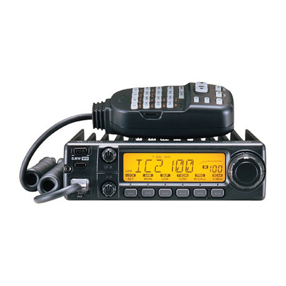
Page 6: Panel Description
PANEL DESCRIPTION Front panel S.MW q SELECT MEMORY/MEMORY WRITE SWITCH [S.MW(MW)] Selects a memory channel for programming. (p. 26) Programs selected memory when pushed and held. (p. 27) w POWER SWITCH [PWR] Turns power ON and OFF when pushed momentarily. e SQUELCH CONTROL [SQL] Varies the squelch level. - Page 7 Each push changes the output power selection. (p. 19) • There are 3 output powers available: low, mid and high (the IC-2100-T Thailand and IC-2100H Taiwan versions have only 2 output powers). Push and hold to select a duplex setting. (p. 21) •...
-
Page 8: Function Display
PANEL DESCRIPTION Function display MUTE LOCK q TRANSMIT INDICATOR Appears while transmitting. (p. 19) Flashes while transmitting with the one-touch PTT func- tion. (p.20) w DUPLEX INDICATORS (p. 21) “DUP–” or “DUP” appears during semi-duplex operation (repeater operation). e TONE INDICATORS “T”... - Page 9 PANEL DESCRIPTION !3 OUTPUT POWER INDICATORS (p. 19) “MID” appears when mid output power is selected. • The IC-2100T Thailand and IC-2100H Taiwan versions have no mid output power. “LOW” appears when low output power is selected Neither indicator appears when high output power is se- lected.
-
Page 10: Rear Panel
PANEL DESCRIPTION Rear panel q SPEAKER JACK [SP] Accepts an 8 speaker. • Audio output power is more than 2.4 W. w POWER RECEPTACLE [DC13.8V] Accepts 13.8 V DC ±15% with the supplied DC power cable. • Current of 12 A or greater is required. NOTE: DO NOT use a cigarette lighter socket as a power source when operating in a vehicle. -
Page 11: Microphone
Microphone (HM-98S*) LOCK CALL DTMF-S FUNC PTT-M MONI SCAN PRIO DTMF D-OFF HIGH TONE TSQLS TSQL T-OFF DUP– DUP+ SIMP TONE-1 TONE-2 16KEY LOCK MUTE * A different microphone may be supplied depend- ing on transceiver ver- q UP/DOWN SWITCHES [Y]/[Z] Push either switch to change operating frequency, mem- ory channel, set mode contents, etc. -
Page 12: Microphone Keypad
PANEL DESCRIPTION Microphone keypad FUNCTION Toggles between opening and closing the MONI squelch. Starts and stops scanning. SCAN PTT-M Starts and stops priority watch. PRIO Selects high output power. HIGH Selects mid output power. DTMF Selects low output power TONE Selects –duplex. - Page 13 FUNCTION Clears a digit before entry. Cancels the scan, priority watch or DTMF memory function. (pgs. 16, 37, Enters set mode and advances the set D-OFF mode selection. Sets the keypad for numeral input T-OFF Decreases the set mode selection order after entering set mode.
-
Page 14: Installation
INSTALLATION Location Select a location which can support the weight of the trans- ceiver and does not interfere with driving in any way. We rec- ommend the locations shown in the diagram below. NEVER place the transceiver where normal operation of the vehicle may be hindered or where it could cause bodily injury. -
Page 15: Battery Connection
Battery connection NEVER connect the transceiver directly to a 24 V battery. DO NOT use the cigarette lighter socket for power con- nections. Attach a rubber grommet when passing the DC power cable • CONNECTING TO A DC POWER SOURCE •... -
Page 16: Antenna Installation
INSTALLATION Antenna installation D Antenna location To obtain maximum performance from the transceiver, select a high-quality antenna and mount it in a good location. A non- radial antenna should be used when using a magnetic mount. Roof-mount antenna (Drill a hole or use a magnetic mount.) Gutter-mount antenna D Antenna connector The antenna uses a PL-259 connector. -
Page 17: Setting A Frequency
Preparation D Turning power ON/OFF NOTE: Before operating the transceiver for the first time it’s a good idea to reset the transceiver’s CPU. This will en- sure that all transceiver settings are at their defaults. See p. 62 for CPU resetting details. Push [PWR] for 1 sec. -
Page 18: Lock Functions
SETTING A FREQUENCY Lock functions To prevent accidental frequency changes and unnecessary function access, use the lock function. The transceiver has 2 different lock functions. D Frequency lock This function locks the tuning dial and switches electronically and can be used together with the microphone lock function. Push and hold [ LOCK] until “L”... -
Page 19: Using The Tuning Dial
Using the tuning dial Rotate the tuning dial to set the frequency. • If VFO mode is not selected, push [V/MHz] to select VFO mode. • The frequency changes according to the selected tuning steps. (p. 16) To change the frequency in 1 MHz (10 MHz for some ver- sions) steps, push [V/MHz], then rotate the tuning dial. -
Page 20: Tuning Step Selection
SETTING A FREQUENCY Tuning step selection Tuning steps are the minimum frequency change increments when you rotate the tuning dial or push the [Y]/[Z] keys on the microphone. The following tuning steps are available: • 5 kHz • 10 kHz •... -
Page 21: Using The Keypad
Using the keypad The frequency can be directly set via numeral keys on the microphone. Ä Push [VFO] to select VFO mode, if necessary. Å Push [ENT] to activate the keypad for digit input. [EXAMPLE]: Setting the frequency to 145.3625 MHz. SETTING A FREQUENCY Ç... -
Page 22: Basic Operation
BASIC OPERATION Receiving Push [PWR] for 1 sec. to turn power ON. Set the audio level. Push [MONI] to open the squelch. Rotate the [VOL] control to adjust the audio output level. Push [MONI] again to close the squelch. Set the squelch level. Rotate [SQL] fully counterclockwise in advance. -
Page 23: Transmitting
Transmitting vCAUTION: Transmitting without an antenna will damage the transceiver. NOTE: To prevent interference, listen on the frequency be- fore transmitting by pushing [MONI] or [ MONI] on the mi- crophone. Set the operating frequency. (pgs. 15, 17) • Select output power if desired. See section at right for details. Push and hold [PTT] to transmit. -
Page 24: One-Touch Ptt Function
BASIC OPERATION One-touch PTT function The PTT switch can be operated as a one-touch PTT-M PTT switch (each push toggles transmit/receive). Using this function you can transmit without push- ing and holding the PTT switch. To prevent accidental, continuous transmissions with this function, the transceiver has a time-out timer. -
Page 25: Repeater Operation
Accessing a repeater Set the receive frequency (repeater output frequency). (pgs. 15–17) Push and hold [ DUP] for 1 sec., one or more times, (LOW) to select minus duplex or plus duplex. • “DUP –” or “DUP” appears to indicate the transmit frequency for minus shift or plus shift, respectively. - Page 26 REPEATER OPERATION D DTMF tones Push [DTMF-S], then push the keys of the desired DTMF S DTMF digits. • The function indicator lights green. • 0–9, A–D, M(E) and #(F) are available. • Cancel the DTMF memory encoder function in ad- vance, if necessary.
-
Page 27: Subaudible Tones
Subaudible tone (encoder function) The display shows that an 88.5 Hz subaudible tone frequency is set for re- peater use. Select the mode/channel you wish to set the subaudible tone encoder frequency to, such as VFO mode or mem- ory/call channel. Push [SET] one or more times until “T”... -
Page 28: Offset Frequency
REPEATER OPERATION Offset frequency Select the mode/channel you wish to set the subaudible tone frequency to, such as VFO mode or memory/call channel. • The offset frequency can be individually programmed into each mode or channel. Push [SET] one or more times until “DUP” appears and flashes as shown above. -
Page 29: Auto Repeater
Auto repeater USING (USA version) The USA version automatically activates the repeater settings (DUP or – DUP and tone encoder ON/OFF) when the operat- ing frequency falls within the general repeater output fre- quency range and deactivates them when outside of the range. -
Page 30: Memory Operation
MEMORY OPERATION General description The transceiver has 107 memory channels including 6 scan edge memory channels (3 pairs), and 1 call channel. In addi- tion, 6 scratch pad memories are available (see p. 34). Each of these channels can be individually programmed with the following data. -
Page 31: Programming A Memory Channel
Programming a memory channel VFO mode settings, including the set mode contents such as subaudible tone frequency, etc., can be programmed into a memory channel. Set the desired frequency in VFO mode: Push [V/MHz] to select VFO mode. Set the frequency using the tuning dial. Set other data (e.g. -
Page 32: Programming A Memory Channel Via The Microphone
MEMORY OPERATION Programming a memory channel via the microphone The microphone can also be used to program memory channels. Ä Set the desired frequency in VFO mode: Push [VFO] to select VFO mode. Set the frequency using the keypad. Set other data (e.g. offset frequency, duplex direction, subaudible tone encoder ON/OFF and its frequency), if necessary. -
Page 33: Transferring Memory Contents
Transferring memory contents This function transfers a memory channel’s contents to VFO (or another memory/call channel). This is useful when search- ing for signals around a memory channel frequency and for recalling the offset frequency, subaudible tone frequency, etc. S.MW Push for 1 sec. -
Page 34: Memory Clearing
MEMORY OPERATION Memory clearing Contents of programmed memories can be cleared (blanked), if desired. Push [S.MW] momentarily. Select the memory channel to be cleared with the tuning dial. Push [S.MW] briefly, then a second time for 1 sec. • 3 beeps sound, then the frequency is cleared. •... -
Page 35: Alphanumeric Display
Alphanumeric display Each memory channel and the call channel can be pro- grammed with an alphanumeric name such as a repeater name, club name, etc., for easy recognition. Names can be a maximum of 6 characters—see the table below for avail- able characters. -
Page 36: Call Channel Operation
CALL CHANNEL OPERATION Calling up the call channel Use the call channel to store a most-often-used frequency for quick recall. Push [M/CALL] one or twice to display a large “C” in the memory channel readout. Push [V/MHz] or [M/CALL] to exit the call channel. Large “C”... -
Page 37: Programming The Call Channel
Programming the call channel In addition to an operating frequency, duplex information, sub- audible tone information (tone encoder or tone squelch ON/OFF and its frequency) and an alphanumeric name can be programmed into the call channel. Push [M/CALL] one or twice to display a large “C” in the memory channel readout. -
Page 38: Scratch Pad Memory
SCRATCH PAD MEMORY What is scratch pad memory? During VFO operation, the transceiver automatically memo- rizes operating frequency information when transmitting on a new frequency. There are 2 types of scratch pad memories, those for simplex operation, L1–L3, and those for duplex (re- peater) operation, r1–r3. -
Page 39: Transferring Scratch Pad Memory Contents
Ä Push and hold [ CALL] for 1 sec. to select (MR) CALL the call channel. Å Push [Y] one or more times to select a duplex scratch pad memory; push [Z] one or more times to select a simplex scratch pad memory. Ç... -
Page 40: Scan Operation
SCAN OPERATION Scan types Scanning searches for signals automatically and makes it easier to locate new stations for contact or listening purposes. FULL SCAN (p. 37) Band Band edge edge Scan Jump MEMORY SCAN (p. 37) SKIP SKIP M 100 NOTE: A tone scan function is available to search for sub- audible tones (e.g. -
Page 41: Scan Start/Stop
Scan start/stop D Preparation Common setting: scan resume condition (p. 41) For programmed scan: program the scan edges (p. 38) For memory scan: program 2 or more memory chan- nels; set memory skip settings, if desired (p. 40) D Operation Select VFO mode for full/programmed scan with [V/MHz];... -
Page 42: Programming Scan Edges
SCAN OPERATION Programming scan edges Scan edges can be programmed in the same manner as memory channels. Scan edges are programmed into scan edges, 1A/1b to 3A/3b, in memory channels. Set the desired frequency in VFO mode: Set the frequency using the tuning dial. Set other data (e.g. -
Page 43: Programming Scan Edges Via The Microphone
Programming scan edges via the microphone Ä Set the desired frequency in VFO mode. Push [VFO] to select VFO mode. Set the frequency using the keypad. Å Push [FUNC] then [EMW] momentarily. Ç Push Y] or [Z] to select scan edge channels. É... -
Page 44: Skip Channel Setting
SCAN OPERATION Skip channel setting The memory skip function speeds up scanning by checking only those memory channels not set as skip channels. Set skip channels as follows. SKIP Select a memory channel: Select memory mode by pushing [M/CALL] once or twice. -
Page 45: Scan Resume Condition
Scan resume condition The scan resume condition can be selected as timer, pause or empty pause scan. The empty pause scan is useful for finding unused frequencies. The selected resume condition is also used for priority watch. (p. 42) The display shows that the scan will resume 15 sec. -
Page 46: Priority Watch
PRIORITY WATCH Priority watch types Priority watch checks for signals on a memory or call chan- nel every 5 sec. while operating on a VFO frequency. The transceiver has 3 priority watch types to suit your needs. You can transmit on the VFO frequency while the priority watch operates. -
Page 47: Priority Watch Operation
Priority watch operation Select VFO mode; then, set an operating frequency. Set the watching channel(s). For memory channel watch: Select the desired memory channel. For memory scan watch: Select memory mode; then, push [ (V/MHz) to start memory scan. For call channel watch: Select the call channel by pushing [M/CALL] once or twice. -
Page 48: Dtmf Memory Encoder
DTMF MEMORY ENCODER Programming a DTMF code DTMF codes are used for autopatching, accessing repeaters, controlling other equipment, etc. The transceiver has 14 DTMF memory channels (d0–d9, dA–dd) for storage of often- used DTMF codes of up to 16 digits. Ä... -
Page 49: Transmitting A Dtmf Code
Transmitting a DTMF code D Automatic transmission (DTMF memory) Ä Push [FUNC] then [ DTMF] to turn the DTMF DTMF memory function ON. • “d” appears in place of the 100 MHz digit. Å Push [FSET] to enter the programming condi- tion. -
Page 50: Pocket Beep And Tone Squelch
POCKET BEEP AND TONE SQUELCH Pocket beep operation This function uses subaudible tones for calling and can be used as a “common pager” to inform you that someone has called while you were away from the transceiver. D Waiting for a call from a specific station Set the operating frequency. -
Page 51: Tone Operation
Tone squelch operation The tone squelch opens only when receiving a signal with the same pre-programmed subaudible tone. Set the operating frequency. Program the subaudible tone frequency in set mode. • See p. 23 for programming details. Push [TONE] one or more times to indicate “T SQL” ap- pears in the function display. -
Page 52: Tone Scan
POCKET BEEP AND TONE SQUELCH Tone scan By monitoring a signal that is being transmitted on a repeater input frequency, you can determine the tone frequency nec- essary to open a repeater. Set the frequency to be checked for a tone frequency e.g. a repeater input frequency. -
Page 53: Wireless Operation
HM-90, since the HM-90’s internal battery re- quires charging. D Recommended connection Use the microphone cable IC-2100H EX-1759 WIRELESS OPERATION HM-90 WIRELESS MICROPHONE The HM-90’s internal battery should be charged when the mi- crophone is not being held. -
Page 54: Ex-1759 Installation
WIRELESS OPERATION EX-1759 installation The EX-1759 INFRARED RECEIVER ent purposes depending on the HM-90 charger. This is be- cause the EX-1759 has both an infrared receiver and a microphone connector which contains microphone charging capabilities. When using the BC-96 with external DC input Attach the EX-1759 to a suitable location for receiving in- frared signals, e.g. -
Page 55: Hm-90 Switches
HM-90 switches BAND SELECT MONI REMOTE CONTROL MICROPHONE Front and side panels q PTT SWITCH Push and hold to transmit; release to receive. Toggles between transmitting and receiving while the one-touch PTT function is in use. w BAND SWITCHES [BAND SELECT Y,Z] No function. - Page 56 WIRELESS OPERATION FUNCTION Selects the call channel. CALL AFC-OFF Selects memory mode. PTT-M Selects VFO mode. Selects high output power. HIGH C-SQL Selects mid output power. DTMF Selects low output power. TONE DUP– Selects –duplex. T-SQLS DUP + Selects +duplex. T-SQL Selects simplex.
- Page 57 Enters set mode and advances the set mode selection order. Decreases the set mode selection order T-OFF after entering set mode. SPCH NOTE: The IC-2100H has no voice synthesizer function. DEMO Sets the keypad for numeral input. SCAN Toggles between opening and closing MONI the squelch.
-
Page 58: Microphone Address
WIRELESS OPERATION Microphone address The transceiver has 8 possible microphone addresses (in- cluding OFF) to help prevent interference from other HM-90 wireless microphones. Set both the microphone address and microphone dip switch to the same value as follows. NOTE: When the supplied microphone is connected, the transceiver rejects control signals from the HM-90 even when the microphone address is matched. -
Page 59: Other Functions
Beep tones USING on/off You can select silent operation by turning beep tones OFF or you can select to have confirmation beeps sound at the push of a switch by turning beep tones ON. Push [PWR] to turn power OFF. While pushing [SET], turn power ON to enter initial set mode. -
Page 60: Auto Power-Off
OTHER FUNCTIONS Auto power-off The auto power-off function conveniently turns the transceiver power OFF after a preset time in which no operations are per- formed. In this way, if you forget to turn power OFF, the trans- ceiver automatically turns itself OFF. The time can be set to 30 min., 1 hr., 2 hr. -
Page 61: Microphone [F-1]/[F-2] Keys
Microphone [F-1]/[F-2] keys Switches on the transceiver’s front panel can be assigned to the microphone’s [F-1] and [F-2] keys. Turn power OFF. While pushing the desired switch on the transceiver and [F-1] or [F-2] on the microphone, turn power ON. •... -
Page 62: Display Color
The display shows that green is Push [V/MHz] to return to selected for the color. normal operation. The Europe version of the IC-2100H comply with European SET MODE USING regulations regarding narrow FM bandwidth operation on am- ateur transceivers. Wide and narrow FM operation differ in the following specifications:... -
Page 63: Data Cloning
Data cloning Cloning allows you to quickly and easily transfer the pro- grammed contents from one transceiver to another; or , data from a PC to a transceiver using the optional CS-2100 CLONING SOFTWARE Connect the OPC-474 cloning cable with adapter plugs to the [SP] jack of the master and slave transceivers. -
Page 64: Maintenance
MAINTENANCE Troubleshooting PROBLEM No power comes on. • Power connector has a poor contact. • Polarity of the power connection is reversed. • Blown fuse. No sound comes from the • Volume is too low. speaker. • The audio mute function is activated. •... - Page 65 PROBLEM POSSIBLE CAUSE Some memory channels • The input channel number has not yet been pro- cannot be selected via the grammed. microphone keypad. Scan does not operate. • The squelch is open. • The selected scan edge memory channels (e.g. 1A and 1b) have the same frequencies (for pro- grammed scan).
-
Page 66: Fuse Replacement
MAINTENANCE Fuse replacement If the fuse blows or the transceiver stops functioning, find the source of the problem if possible, and replace the damaged fuse with a new, rated one (FGB 20 A) as shown below. Partial CPU resetting If you want to initialize the operating conditions without clear- ing the memory contents, etc., a partial reset function is avail- able for the transceiver. -
Page 67: Specifications
General • Frequency coverage VERSION TRANSMIT 144–148 MHz Europe 144–146 MHz Australia 144–148 MHz Taiwan 144–146 MHz Asia 144–148 MHz IC-2100-T (Thailand) 144–146 MHz* *Guaranteed 144–148 MHz only. • Mode : FM • No. of memory channels : 113 (including 3 scan edge pairs, 6 scratch pad memories and 1 call) •... -
Page 68: Options
OPTIONS Some of the following options may not be available due to variations in local electrical standards, etc. If you have any questions regarding options please consult your Icom dealer. D Speakers SP-10 EXTERNAL SPEAKER Compact design. Cable length: 1.5 m; 4.9 ft. - Page 69 D Hand microphones HM-77/A DTMF microphone with DTMF memory function. HM-78, HM-96, HM-118 Regular hand microphones. HM-79, HM-97 Equipped with a tone call function. HM-95 DTMF microphone. HM-98S Remote control microphone with keypad backlighting. HM-118T/TA DTMF microphones with keypad backlighting. D Other accessories HS-62 FLEXIBLE MOBILE MICROPHONE + HS-15B SWITCH BOX + OPC-589 ADAPTER CABLE...
-
Page 70: Mode Arrangement
MODE ARRANGEMENT LOCK MONI [V/MHz] LOCK SCAN PRIO SCAN MONI TONE CALL V MHz MEMORY MODE (p.26) LOCK SCRATCH PAD SIMPLEX MEMORY (p. 34) VFO MODE (p. 13) SCAN PRIO SCAN TONE CALL V MHz [M/CALL] [V/MHz] LOCK MONI [M/CALL] CALL CHANNEL (p. - Page 71 SET MODE Display backlighting (p. 58) Display color (p. 58) Repeater tone frequency (p. 23) Subaudible tone T SQL frequency (p. 47) [SET] Offset frequency (p. 24) Tuning step* (p. 16) *from VFO mode Scan resume condition (p. 41) Wide/narrow setting (p.
- Page 72 Count on us! A-5492H-1EX- Printed in Japan 1-1-32 Kamiminami, Hirano-ku, Osaka 547-0003 Japan Copyright 1997 Icom Inc.
Need help?
Do you have a question about the IC-2100H and is the answer not in the manual?
Questions and answers