Icom IC-2100H Service Manual
Hide thumbs
Also See for IC-2100H:
- Instruction manual (72 pages) ,
- Service manual (39 pages) ,
- Service manual (30 pages)
Table of Contents
Advertisement
Quick Links
Advertisement
Table of Contents

Subscribe to Our Youtube Channel
Related Manuals for Icom IC-2100H


Summary of Contents for Icom IC-2100H
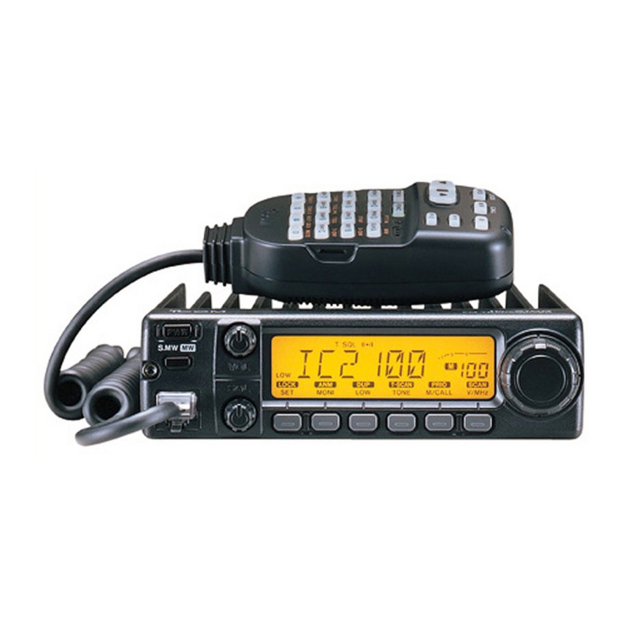
- Page 1 TRANSCEIVER 144MHz FM IC-2100H IC-2100-T learn Inc.
- Page 2 NEVER This service manual describes the latest service information connect the transceiver to an AC outlet or to a DC IC-2100H/IC-2100-T 144 MHz FM for the TRANSCEIVER at power supply that uses more than 16 V. This will ruin the the time of publication.
-
Page 3: Table Of Contents
TABLE OF CONTENTS SECTION SPECIFICATIONS SECTION INSIDE VIEWS SECTION CIRCUIT DESCRIPTION RECEIVE R CI RCUITS • • • 3- 2 T RAN S MllTER CIRCUITS 3·2 ... . PLL C I RCUITS . -
Page 4: Specifications
SECTION 1 SPECIFICATIONS •GENERAL Frequency range Version Receive Transmit • EUR, TPE , 144.000- 146 . 000 144.000 - 146.000 ITA, SEA, 13 6.000-174.000* 1 3 6 . 000-174.000* 1 3 6.000 -1 74.000* 1 40.000 - so.000· only *Specifications 144.000 148.000 MHz •Mode... -
Page 5: Inside Views
SECTION INSIDE VIEWS •MAIN UNIT IC4: SC-1091 for IC·2100H SC-1005 for IC·2100- 1st IF filter (F11: FL-288) AF Power amplffier -- (ICS· TA7252AP) 2nd IFfilter (Fl2: CFWS450F) VCO circuit---- -- 2nd IF fi l ter (F13: CFWS450HT) [EUR], [ITA] only (X2: CDB450C24) (X1: CR·549) RF amplifi e r----... -
Page 6: Circuit Description
SECTION CIRCUIT DESCRIPTION 3-1 RECEIVER CIRCUITS 3·1-5 2ND IF AND DEMODULATOR CIRCUITS (MAIN unit) 3-1·1 ANTENNA SWITCHING CIRCUIT {MAIN unit) The 2nd mixer circuit converts the 1st signal to a 2nd The antenna switching circuit functions as a low-pass filter signal. -
Page 7: T Ran S Mllter Circuits
unit) a.2-3 a.1-7 SQUELCH CIRCUIT (MAIN and LOGIC units) DRIVE AMPUAER CIRCUIT (MAIN • The drive amplifier circuit amplifies the VCO oscillating signal NOISE SQUELCH to the level needed at the power amplif i e r. The noise squelch circuit cuts out A F signals when no R F sig nals are received. -
Page 8: Pll Circuits
3-4 POWER SUPPLY CIRCUITS 3-3 PLL CIRCUITS 3·3·1 PLL CIRCUIT VOLTAGE LINES A PLL circuit provid es stable oscillation o f the transmit fre Description Line quency and the receive 1st LO frequency. The PLL circuit compares the phase of the d ivided VCO frequency to the ref The voltage from the connected DC power sup- erence frequency. -
Page 9: Port Allocations
3-5 PORT ALLOCATIONS 3·5'-1 CPU (LOGIC UNIT IC1) Port Port Description Description number name number name cress Input port for the PTT sw i t ch. nput port f o r the decode sig- TONEIN nals. High : While PTT switch I s pushed. Input port to detect remote microphon Input port for the reset signal. -
Page 10: Adjustment Procedures
SECTION ADJUSTMENT PROCEDURES 4-1 PREPARATION All adjustments in this section must performed on wide bandwidth condit i o n unless specified otherwise. ( N arrow bandwidth is selectable for Europe and Italy vertions only.) •REQUIRED TEST EQUIPMENT EQUIPMENT GRADE AND RANGE EQUIPMENT GRADE AND RANGE Output voltage... -
Page 11: Pll Adjustments
4-2 PLL ADJUSTMENTS ADJUSTMENT MEASUREMENT POINT ADJUSTMENT ADJUSTMENT CONDmoN VALUE UNIT LOCATION UNIT ADJUST • Displayed frequency : MAIN 1.25-1.30 PLL LOCK Connect a digital MAIN VOLTAGE 14 5.000 MHz multi-meter or oscil- •Receiving loscope check point CP1. • Transmitting 1.45-1.55 •... -
Page 12: Transmitter And Receiver Adjustments
3 TRANSMITTER AND RECEIVER ADJUSTMENTS The receiver adjustments must performed after PLL ADJUSTMENTS. ADJUSTMENT MEASUREMENT POINT VALUE ADJUSTMENT ADJUSTMENT CONDITION ADJUST UNIT LOCATION UNIT • Displayed frequency : Rear Connect W [T MAIN POWER 145.000 [EUR, TPE, THA] Panel power meter to the 25 W [TPE] 146.000 [ITA, USA, SEA,... - Page 13 power supply 13.8 V /20A Sensitivity adjustment Output power adjustment R163 Deviation Squelch adjustment adjustment Sensitivity check point JIG CONNECTOR • · ·• to micro hone connector 2.2k0 \� _ _ _ ___________________ ,,...
- Page 14 SECTION PARTS LIST [LOGIC UNIT] [LOGIC UNIT] ORDER ORDER DESCRIPTION DESCRIPTION S.RESISTOR ERJ3GEYJ 104 V (100 kn) 114 000 7 020 S.IC H064338 7 5A83H 7030003680 (THAI only EAJ3GEYJ 391 V (390 O} other S.RESISTOR 114000 7 420 S.IC HD6433875A85H 7030003 390 MCRSOJZHJ 18 0 (180) S.IC...
- Page 15 [LOGIC UNIT] [LOGIC UNIT] ORDER ORDER DESCRIPTION DESCRIPTION 4030009980 S.CERAMIC C16o8 1H 152K-T-A 7030003440 S.RESISTOR ERJ3GEYJ 102 V (1 kn} ERJ3GEYJ 102 V (1 kn) 4030008630 $.CERAMIC C1608 1C 104Z-T·A 7030003440 S.RESISTOA C1608 JF 1C 1 04Z·T·A S.RESISTOA ERJ3GEYJ 103 V (10 kn) 4030008630 $.CERAMIC 7030003560 $.CERAMIC...
- Page 16 [LOGIC UNIT] [MAIN UNIT] ORDER ORDER DESCRIPTION DESCRIPTION 712000 0 470 JUMPER ERDS2TO [THAJ only 1SS35S TE-17 1750000SSO S.DIODE 1720000370 S.VARICAP l'IVU350TRF 1720000370 S.VARICAP HVU350TRF 0910049542 8 50978 HVU350IBF 1720000370 S.VARICAP SRCN-2088-SP-N-W S930045730 LCD CONTACT 1720000370 S.VARICAP HVU350TRF MA742 (TX) 179000 0980 S.DIODE MA8 047- M (TX) 1730002340 $.ZENER...
- Page 17 [MAIN UNIT] [MAIN UNIT] ORDER ORDER DESCRIPTION DESCRIPTION A2 4 7030003760 $.RESISTOR ERJ3GEYJ 474 V (470 A110 7030003620 $.RESISTOR k.Cl) ERJ3GEY J 333 V (33 703000 3 420 $.RESISTOR ERJ3GEYJ 681 V (680 0) A111 7510000890 S.THERMISTOR NTCCF2012 3EH 411KC-T S.THERMISTOR 7510000420 TN20-3W472LT...
- Page 18 [MAIN UNIT] [MAIN UNIT] ORDER ORDER DESCRIPTION DESCRIPTION 4030001830 S.CERAMIC GRM40 RH 330J SOPT 40300068 6 0 S.CEAAMIC C1608 JB 1 H 102K·T·A C116 C117 4030001820 S.CERAMIC GRM40 RH 220.J SOPT 403000 6 860 $.CERAMIC C1608JB 1H 102K·T·A $.CERAMIC C118 4030001610 $.CERAMIC GRMAO RH 180J SOPT...
- Page 19 [MAIN UNln ORDER DESCRIPTION $.CERAMIC C1608 Ct1 1t1 101J·T-A C206 4030007130 C207 4030008750 $.CERAMIC C1608 CH 1 H 360J-T-A $.CERAMIC C1608 CH 1 H 0800-T-A C208 4030006990 4030007000 S.CERAMIC C1608 CH 1H 0900-T-A C209 C1608JB 1H 1Q2.K·T·A C210 S.CERAMIC 4030009570 $.CERAMIC C1608 CH 1H OR38-T-A C211...
-
Page 20: Mechanical Parts And Disassembly
SECTION 6 MECHANICAL PARTS AND DISASSEMBLY [CHASSIS PARTS] [ACCESSORIES] QTY. QTY. REF. NO. ORDER NO. REF. NO. ORDER NO. DESCRIPTION DESCRIPTION 52100000 S O (20A) 6510004880 MR·DSE·01 Fuse Antena connector Optional [EUR), [ITA] prodOOI Mi c rophon HM-97 2510000 8 20 Speaker VS·57·0S14 Opti on al product Microphon... - Page 21 J1 (C) MP10 (L) LOGIC UNIT R61 (L) � MP16(C} MP2 (L) EP2 (L) MP15 (C) OSI (L) MPS (L) MP3 (L) MP6(C) 59 (l) MAIN UNIT MP8 (C) W1 (M) ..'!..MPS(C) MP6 (L) MP1 (M) -�.
-
Page 22: Semi-Conductor Information
SECTION 7 SEMI-CONDUCTOR INFORMATION • TRANSISTOR AND FET'S 2SA1576 R 2SA1734 2SC2954 2SC3357 2SC4081 R (Symbol; (Symbol: (Symbol; AK) (Symbol: :�' :�' 2SC4081 S 2SC4116 2SC4213 B 2SC4215 2SC4226 R25 R25) (Symbol: (Symbol: (Symbol: (Symbol: :� ' :�' � � :�' 2S0999 CK 2SJ144... -
Page 23: Logic Unit
8-1 LOGIC UNIT • TOP VIEW � E � Microphone 8 - 1... - Page 24 � §? §? to MAIN unit J2 10 MAIN uni1 8 - 2...
- Page 25 8-2 MIAN UNIT • TOP VIEW CHASSIS to Speaker ro Logic unit J3 8 - 3...
- Page 26 VIEW BOTTOM • 1£'1i) 8 - 4...
- Page 29 lcom Inc. Osal<a Kamlhigashi, Hirano-ku. · 6-9· 16, 547-0002 . Japan Phone 06 793 5302 06 7 9 3 0013 lcom (Europe) G'mbH lcom America Inc. 2380 11 6 111 Avenue N E., Bellwue, WA 9800-I . U.S.A Sir, 100. D-o022� DOsMlclol1 , GermeJ1Y HeadquaMrs >...
- Page 30 A - 54921-S lcom lnc. Printed in Japan Kamihigashi, Hirano-ku, Osaka, Japan 547-000 2 , 6 - 9 -16, ©> 1998 lcom Inc.
Need help?
Do you have a question about the IC-2100H and is the answer not in the manual?
Questions and answers