Table of Contents
Advertisement
Advertisement
Table of Contents

Related Manuals for Atlas Copco PTS 916 Cd


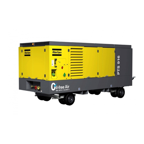
Summary of Contents for Atlas Copco PTS 916 Cd
- Page 1 Instruction Manual for Portable Compressors PTS 916 Cd...
- Page 3 Instruction Manual for Portable Compressors PTS 916 Cd Instruction manual .................. 5 Circuit diagrams ..................57 Printed Matter N° Preliminary ATLAS COPCO - PORTABLE AIR DIVISION 07/2007 www.atlascopco.com...
- Page 4 The manufacturer does not accept any liability for any damage arising for modifications, addi- tions or conversions made without the manufacturer's approval in writing. Copyright 2007, Atlas Copco Airpower n.v., Antwerp, Belgium. Any unauthorized use or copying of the contents or any part thereof is prohibited.
-
Page 5: Table Of Contents
Instruction manual Congratulations on the purchase of your AC compressor. It is a solid, safe and reliable machine, built according to the latest technology. Follow the instructions in this booklet and we guarantee you years of troublefree operation. Please read the following instructions carefully before starting to use your machine. - Page 6 PTS 916 Cd 5 Maintenance and service 6 Problem solving ........39 ............. 50 5.1. Preventive maintenance schedule....40 6.1. Problem solving chart........50 5.2. Service paks and kits ........40 6.2. Battery and alternator precautions ....50 5.2.1. Service paks............40 6.3.
-
Page 7: Safety Precautions For Portable Compressors
The policy of Atlas Copco is to provide the users of their equipment with safe, If any statement in this manual does not comply with local legislation, the reliable and efficient products. -
Page 8: Safety During Transport And Installation
13 Never refill fuel while the unit is running, unless otherwise stated in the For maximum safety and efficiency of the lifting apparatus all lifting Atlas Copco Instruction Book (AIB). Keep fuel away from hot parts such members shall be applied as near to perpendicular as possible. If required, as air outlet pipes or the engine exhaust. -
Page 9: Safety During Maintenance And Repair
80°C (175°F) and which may be accidentally touched by which are in good condition. personnel shall not be removed before the parts have cooled to room Parts shall only be replaced by genuine Atlas Copco replacement parts. temperature. All maintenance work, other than routine attention, shall only be 19 Never operate the unit in surroundings where there is a possibility of undertaken when the unit is stopped. -
Page 10: Tool Applications Safety
PTS 916 Cd 21 When using cartridge type breathing filter equipment, ascertain that the Piping and coolers correct type of cartridge is used and that its useful service life is not (according to directive 97/23) surpassed. 22 Make sure that oil, solvents and other substances likely to pollute the Safety valves environment are properly disposed of. -
Page 11: Leading Particulars
Instruction manual Leading particulars 2.1 Description of safety pictograms used in this manual This symbol draws your attention to dangerous situations. The operation concerned may endanger persons and cause injuries. This symbol is followed by supplementary information. Preliminary... -
Page 12: Markings And Information Labels
PTS 916 Cd 2.2 Markings and information labels Dangerous outlet Compressor oil drain Danger, heat flat Read the instruction manual before starting Electrocution hazard Service every 24 hours Warning! Atlas Copco engine oil Part under pressure Manual Do not stand on outlet valves... -
Page 13: Abbreviations
Instruction manual 2.3 Abbreviations Atlas Copco Atlas Copco Instruction Book Service Bulletin Atlas Copco List Charge Air Cooler Controller Area Network Interface Compressor Control Module Diagnostic Data Reader Engine Control Module Engine Operation Manual Low-pressure Maximum Minimum Medium-pressure Portable Air Division... - Page 14 PTS 916 Cd Aftercooler 1 Emergency stop Aftercooler 2 Cooling fan 1 (RAD, IC, AC , OC) Air intake filter (compressor) Cooling fan 2 (AC , CAC/FC) Air intake filter (engine) Fuel cooler Alarm lamp Primary fuel filter Air outlet valve...
-
Page 15: General Description
The cooling air is generated by an axial fan, which The PTS 916 Cd is built for a nominal effective working pressure is belt-driven from the engine fan shaft. of up to: Water condensate from the water separator is drained through a –... - Page 16 PTS 916 Cd Engine sensor Compressor inputs Unloaded Data Setpoint link Throttle valve Compressor signal Compressor sensor outputs inputs CAN bus CAN card User Compressor Interface Loaded Push-buttons Remote on UI control control inputs User Aftercooler 1 Loading solenoid valve...
-
Page 17: Air Flow System
Instruction manual 2.6 Air flow system Fuel tanks The unit has two interconnected fuel tanks, but can also be Air drawn through the air intake filters (AF ), and unloader (UA) connected to an external fuel tank. into LP compressor element (CE ) is compressed and discharged to the intercooler (IC) where the heat of first-stage compression is Control panel... -
Page 18: Cooling And Lubricating Oil System
PTS 916 Cd 2.7 Cooling and lubricating oil system The oil is then circulated without being filtered. For this reason, it is imperative to replace the oil filter at regular intervals. Oil from the oil sump (OS) of gear casing (GC) is circulated by an... -
Page 19: Fuel System
Instruction manual 2.8 Fuel system fuel selector in horizontal position (internal) fuel selector in vertical position (external) Bypass valve Fuel filter Filler cap (fuel tank) Primary engine fuel filter / water separator Check valve Secondary engine fuel filter Engine Engine fuel pump External fuel supply coupling Fuel shut-off cock Electrical priming pump... -
Page 20: Water System
PTS 916 Cd 2.9 Water system In case of internal fuel supply, fuel from the fuel tanks (FT) is circulated by the engine fuel pump (FP ). The fuel is pumped through a 3-way valve (TWV) to two primary fuel filters (FF... -
Page 21: User Interface And Compressor Control Module
Instruction manual User Interface and Compressor 3.2 Control Control Module Arrow buttons 3.1 Look of User Interface The arrow buttons are generally used to increase or decrease the setpressure. The User Interface consists of a color LCD display which gives the In the Process Info status however, they are used to scroll the text user the essential process information feedback. - Page 22 PTS 916 Cd Enable parameters When the PC mode is active, monitoring the operation on the UI stays possible. Further, the UI can only be used for looking at the There are four enable parameters with four possible conditions. System information and the Process information.
-
Page 23: Functionality
Instruction manual 3.3 Functionality When the operator presses the Stop button in any status from Warmup to Load, the compressor immediately goes to the The start and stop function can be set to manual or automatic Cooldown status. operation. When the cooldown time has elapsed, the stopping procedure It is possible to combine these two into a semi-automatic operation. -
Page 24: A Closer Look At Some Operating Procedure Blocks
PTS 916 Cd 3.3.3 A closer look at some operating Warming up procedure blocks When the engine starts, the compressor enters the Warmup status. This means the engine is going to run idle until the engine coolant Process information temperature has reached a specific value. If this coolant... - Page 25 Instruction manual Restarting before the parameter is back within its limits is Process warnings Effect impossible, because of the parameter check in the cranking Fuel Level Shutdown procedure. Engine Oil Level Too Low Shutdown Engine Oil Overfill Shutdown Emergency stop LP Element Temperature Shutdown MP Element Temperature...
- Page 26 PTS 916 Cd Unload RPM Control Powerdown It allows compensation of engine power at high altitude To save the batteries, the CCM and UI are equipped with a applications. Powerdown function. In the Unload condition the engine will run at the Unload RPM.
-
Page 27: Operating Instructions
Instruction manual Operating instructions Air Discharge Temperature Control parameter “Disable” When the parameter is disable or disable lock, the PID will regulate 4.1 Parking, transporting and lifting the Air Discharge Temperature to a fixed value of 4°C to prevent instruction freezing. -
Page 28: Transporting Instructions
PTS 916 Cd 4.1.3 Lifting instructions To lift the unit, use a lift truck or crane with sufficient capacity (wet weight of unit is 8260 kg (18213 lb). Use the lifting positions of the unit as shown in the figure below. -
Page 29: Before Starting
Instruction manual 4.2 Before starting 4.3 Starting instructions – With the unit standing level, check the engine and compressor oil Move the control panel power switch to ON. The display of the levels (see section 5.3.2 and 5.3.3). User Interface will light up. See also chapter 3. Add oil if necessary. -
Page 30: Operation Via User Interface
PTS 916 Cd 4.4 Operation via User Interface Automatic start 4.4.1 General In this section an overview is given of all statuses of the CCM. The reactions of the compressor to actions of the operator and to signals from the compressor itself, are also shown. -
Page 31: Permissive Start Status
Instruction manual 4.4.4 Permissive start status 4.4.5 Cranking status In this status the CCM checks if the parameters are out of range and checks all sensor inputs for sensor faults. This status does not require any action from the operator, and is therefore not visible on the screen. -
Page 32: Warmup Status
PTS 916 Cd 4.4.6 Warmup status Automatic start Manual start Warnings Are shown on the screen Shutdowns To shutdown status (see section 4.4.12) Warnings Are shown on the screen Max. warmup time elapsed To Not Loaded status (see Shutdowns To start failure status (see section 4.4.7) or Load/Unload... -
Page 33: Not Loaded Status
Instruction manual 4.4.7 Not Loaded status 4.4.8 Load/Unload status Manual stop Warnings Are shown on the screen Shutdowns To Shutdown status (see section 4.4.12) Emergency stop button To emergency stop status (see section 4.4.13) ↓-button, press once Set pressure - 0.1 bar ↑-button, press once Set pressure + 0.1 bar ↓-button, press continuously... -
Page 34: Cooldown Status
PTS 916 Cd 4.4.9 Cooldown status Automatic stop Warnings Are shown on the screen Shutdowns To shutdown status (see section 4.4.12) Cooldown time elapsed Stopping status (see section 4.4.10) ↓-button, press once Set pressure - 0.1 bar Warnings Are shown on the screen ↑-button, press once... -
Page 35: Start Failure Status
Instruction manual 4.4.11 Start failure status 4.4.12 Shutdown status First a stopping procedure is executed, and the operator has to wait. First a stopping procedure is executed. Sreen A: Start failure, origin in Permissive start status. Sreen B: Start failure, origin in Cranking status. Warnings Are shown on the screen Emergency Stop button... -
Page 36: Emergency Stop Status
PTS 916 Cd 4.4.13 Emergency stop status 4.4.14 System info status Screen A: Emergency Stop is pressed. This status gives a summary of the following parameters: – Unit Type Screen B: Emergency Stop is unlocked. – Unit Serial Number – Engine Serial Number –... -
Page 37: Options Status
Instruction manual 4.4.15 Options status 4.4.16 Process Info status Two key access Depending on the setting of the Infobutton parameter, the operator has access to the Process Info status by pressing a single named function key, the Process Info button. In that case the Infobutton parameter is enable. -
Page 38: During Operation
PTS 916 Cd These parameters are: Other actions and signals have no effect in this status. Shutdowns To Shutdown status (see section 4.4.12) Time-out Back to active compressor status Emergency Stop button To Emergency Stop status (see section 4.4.13) ↓-button Scroll text down ↑-button... -
Page 39: Maintenance And Service
Instruction manual Maintenance and service Maintenance schedule Daily every every every every every every every 1000 2000 3000 4000 8000 10000 hours hours hours hours hours hours hours Service pak 2912 6046 05 2912 6047 06 2912 6048 07 Engine oil level Check Check Check... -
Page 40: Preventive Maintenance Schedule
Extensive laboratory and field endurance tests on Atlas Copco Atlas Copco service kits offer you all the benefits of genuine Atlas equipment have proven PAROIL to match all lubrication demands Copco parts, save on administration costs and are offered at a in varied conditions. -
Page 41: Engine Oil Level
PAROIL 15W40 is a mineral based high performance diesel engine When the warning is generated, the oil level maintainer valve is oil with a high viscosity- index. Atlas Copco PAROIL 15W40 is opened. Oil flows from the oil tank into the oil sump of the engine designed to provide a high level of performance and protection in and into the small oil tank. -
Page 42: Engine Oil And Oil Filter Change
PTS 916 Cd 5.3.4 Engine oil and oil filter change 5.3.5 Compressor oil and oil filter change DRAIN DRAIN engine oil (red) engine oil (red) DRAIN DRAIN DRAIN DRAIN compressor oil (red) coolant radiator (blue) compressor oil (red) coolant radiator (blue) –... -
Page 43: Air Filters Engine/Compressor
Vacuator valve (dust ejector) – Carefully knock the end faces of the filter element on a flat surface The Atlas Copco air filters are specially designed for to remove the dry contaminant. Never strike on a hard surface. Then the application. The use of non-genuine air filters may... -
Page 44: Coolant Level
PTS 916 Cd 5.5 Coolant level Consult the Engine Operation Manual and section 5.5.2 for coolant specifications. 5.5.1 Coolant level check To drain coolant from system, remove drain plugs. Drain plugs are located at the right- and left-hand side under the unit and open the drain cocks (1). -
Page 45: C18 Electrical Fuel Priming Pump Instruction
Instruction manual 5.6.3 Cleaning fuel tanks Consult the preventive maintenance schedule (section 5.1) for replacing intervals. Drain condensate from the primary fuel filters (water separators) regularly by loosening the drain plugs (4). Catch the condensate in To drain sediment and water from the fuel tanks (1), remove the a drain pan. -
Page 46: Poly V-Belt Tension Adjustment
PTS 916 Cd 5.8 Poly V-belt tension adjustment 5.8.1 Poly V-belt cooler fan To check the poly V-belt tension, measure the belt frequency. Use tensioning tool 2913 0022 00. The arrows show where the frequency should be measured. The correct belt frequency is 50 Hz ±2.5 Hz. -
Page 47: Intercooler Relief Valves
Instruction manual 5.10 Intercooler relief valves 5.11 Shutdowns The unit comprises several shutdown sensors: – Engine shutdowns (by ECM): • Engine Coolant Level Sensor Failure • Engine Coolant Temp. Sensor Failure • Engine Oil Temperature Sensor Failure • Engine Fuel Temperature Sensor Failure •... -
Page 48: Battery Care
PTS 916 Cd 5.12 Battery care 5.12.4 Maintaining the battery voltage To maintain the battery voltage, use the unit’s automatic battery Before handling batteries, read the relevant safety charger. precautions and act accordingly. – Battery charger EEC/AUS: 240 VAC / 24 VDC - 100 VA If the battery is still dry, it must be activated as described in section 5.12.2. -
Page 49: Caterpillar Air Shut-Off Valve
Instruction manual 5.14 Caterpillar air shut-off valve 5.17 Electric blow-off valve The air shut-off valve, mounted on the engine, is part of the refinery The blow-off valve, fitted on the MP air inlet pipe, is opened to equipment. This valve prevents combustion air to enter the engine. release air when the air inlet throttle valve is closed;... -
Page 50: Storage
When a compressor element is due for overhaul, it is recommended tight to their terminals. to have it done by Atlas Copco. This guarantees the use of genuine parts and correct tools with care and precision. 6.2 Battery and alternator precautions –... -
Page 51: Trouble Shooting
Replace valve, if necessary. Compressor element(s) not in order. Check interstage pressure and have compressor element(s) inspected by Atlas Copco. Air intake throttle valve remains partially closed. Disconnect loading solenoid valve from throttle valve housing and connect independent compressed-air line to throttle valve housing. - Page 52 PTS 916 Cd Symptom Possible cause Corrective action Compressor capacity or Safety valve or relief valve(s) leaking. Remove and inspect safety valve or relief pressure below normal valve(s). Replace valve(s) if not airtight after reinstallation. Unloading valve leaking. Remove and inspect unloading valve. Replace valve, if necessary.
- Page 53 See problem “Compressor oil pressure too low”. Faulty compressor oil pressure shutdown switch. Remove and test switch. Replace, if out of order. ECM fault. Consult Atlas Copco. Coolant level(s) too low. Check and adjust coolant level(s), if necessary. Crank time too short.
- Page 54 PTS 916 Cd Symptom Possible cause Corrective action Intercooler pressure above Aftercooler clogged internally. Consult Atlas Copco. normal MP compressor element not in order. Have MP compressor element inspected by Atlas Copco. MP silencer and/or check valve give restriction. Check and take corrective action.
-
Page 55: Technical Specifications
Instruction manual Technical specifications 7.3 Compressor/engine specifications Compressor type PTS 916 Cd Designation Unit Value 7.1 Torque values Reference conditions Absolute inlet pressure bar(e) 7.1.1 For general applications Relative air humidity Air inlet temperature °C The following tables list the recommended torques applied for... -
Page 56: Conversion List Of Si Units Into British Units
D ± 4% 250 l/s <FAD The international standard ISO 1217 corresponds to following national standards: MADE BY ATLAS COPCO AIRPOWER n.v. WILRIJK, BELGIUM British BSI 1571 part 1 German DIN 1945 part 1 1615 6945 00 Swedish SS-ISO 1217... - Page 57 Circuit diagrams Preliminary...
- Page 58 Circuit diagram 9822 0899 93/03...
- Page 59 Circuit diagram Controller: a7-f7: System Control Unit ECM: Engine Controle Module - CAT C18 Fuse ECM - 20A Fuse User Interface - 10A Fuse Controller - 20A Fuse Flap Lock Solenoid - 3A Fuse Electrical Priming Pump - 10A Battery 1 Battery 1 Alternator Battery Charger...
- Page 60 Circuit diagram (EC) See 9822 0899 00 Comp Black Watersep. Drain Engine Heater Nozzle Heater Heater 240 V AC AC DC 16 A Drain Heater Switch Black Blue Drain Heater Drain Heater Switch Switch See 9822 0899 00 1604 0068 01 1604 7781 01 1604 7429 02 R1, R2: Coolant heater (engine)
- Page 61 Circuit diagram (USA) See 9822 0899 00 Comp Brown Watersep. Drain Engine Heater Nozzle Heater Heater 120 V AC 120 V AC AC DC 15 A 15 A Drain Heater Switch Brown Blue Drain Heater Drain Heater See 9822 0899 00 Switch Switch 1604 0075 01...
- Page 62 Circuit wiring FRONT SIDE FLAP LOCK TOPTANK CAT LEVEL SW COMP OIL HEATER BLOW OFF COMP HEATER t SW COMP COMP ENGINE HEATER DISCH INTERNAL LIGHT OILER 1604 7429 02 VALVE BATTERY SWITCH CONTINUOUS GROUND FOR 1604 7781 01 INTERNAL LIGHTS DISCH 9822 0899 97 EC 9822 0899 98 USA...
- Page 63 Wiring diagram 1604 7429 03-1...
- Page 64 Wiring diagram 1604 7429 03-2...
- Page 65 Wiring diagram 1604 7429 03-3...
- Page 66 Wiring diagram TERMINAL END A WIRE TERMINAL END B TERMINAL END A WIRE TERMINAL END B TERMINAL MM² COLOR TERMINAL TERMINAL MM² COLOR TERMINAL See note 1 Orange Splice See note 11 Green 1300 See note 7 See note 13 Orange See note 11 Purple...
- Page 67 Wiring diagram Note 1: Connector: Deutsch HD N 36 - 24-19 SN - 059 Note 17:Connector with 6 feet 16-3 cord attached. Terminals: Size 12 (large): Deutsch 0462-203-12141 Delivered with KIM HOTSTART glowplugs Size 16 (small): Deutsch 0462-201-16141 nrs: TF101-000-WOC or TF102-000-WOC. Unused cavities to be sealed with: Deutsch 114017 Middle wire (ground) is separately insulated.
- Page 68 Wiring diagram rear 64 65 1604 7781 02-1...
- Page 69 Wiring diagram rear Note 1: Connector: Deutsch HD N 36 - 24-19 SN - 059 Terminals: Size 12 (large): Deutsch 0462-203-12141 TERMINAL END A WIRE TERMINAL END B Size 16 (small): Deutsch 0462-201-16141 Unused Cavities to be sealed with: Deutsch 114017 TERMINAL MM²...
- Page 70 Wiring diagram (EEC/AUS) Splices 15, 16 Battery Charger in this area These parts must be equipped with a shrinkable sleeve 1604 0068 01 9 10 Application Socket Connector: Deutsch HD N 36-18-8 SN-059 TERMINAL END A WIRE TERMINAL END B Terminals: Deutsch 0462-203-12141 TERMINAL COLOUR...
- Page 71 Wiring diagram (USA) Splices 18, 19, 20 in this area Battery Charger These parts must be equipped with a shrinkable sleeve A1 B1 PE A2 B2 PE 1604 0075 01 9 10 11 12 13 Application Socket Connector: Deutsch HD N 36-18-8 SN-059 TERMINAL END A WIRE TERMINAL END B...
- Page 74 www.atlascopco.com...
Need help?
Do you have a question about the PTS 916 Cd and is the answer not in the manual?
Questions and answers