Table of Contents
Advertisement
Instruction Manual for AC Compressor
English
XAS 188 CD S8 T4F HOP
CALIFORNIA Proposition 65
WARNING
Breathing diesel engine exhaust exposes you to chemicals known to
the State of California to cause cancer and birth defects or other
reproductive harm.
• Always start and operate the engine in a well-ventilated area.
• If in an enclosed area, vent the exhaust to the outside.
• Do not modify or tamper with the exhaust system.
• Do not idle the engine except as necessary.
For more information go to
www.P65warnings.ca.gov/diesel.
Engine Caterpillar C2.2T
Advertisement
Table of Contents

Related Manuals for Atlas Copco XAS 188 CD S8 T4F HOP


Summary of Contents for Atlas Copco XAS 188 CD S8 T4F HOP
- Page 1 Instruction Manual for AC Compressor English XAS 188 CD S8 T4F HOP Engine Caterpillar C2.2T CALIFORNIA Proposition 65 WARNING Breathing diesel engine exhaust exposes you to chemicals known to the State of California to cause cancer and birth defects or other reproductive harm.
- Page 3 Instruction Manual for AC Compressor XAS 188 CD S8 T4F HOP Original instructions Printed matter No. 1310 3018 34 ATLAS COPCO - PORTABLE ENERGY DIVISION 02/2020 www.atlascopco.com...
- Page 4 Neglecting maintenance or making changes to the setup of the machine can result in major hazards, including fire risk. While every effort has been made to ensure that the information in this manual is correct, Atlas Copco does not assume responsibility for possible errors.
-
Page 5: Table Of Contents
Table of contents Preface Maintenance ............34 7.1 Use of service paks..........34 Please read the following instructions carefully before Safety precautions ..........7 7.2 Preventive maintenance schedule....... 34 starting to use your compressor. 1.1 Introduction ............7 7.3 Oil specifications ..........36 It is a solid, safe and reliable machine, built according to 1.2 General safety precautions ........ - Page 6 Disposal ..............48 11.1 General ............... 48 11.2 Disposal of materials .......... 48 Maintenance log ..........49 - 6 -...
-
Page 7: Safety Precautions
1 The owner is responsible for maintaining the unit in a 10 Never operate a machine or equipment beyond its rated The policy of Atlas Copco is to provide the users of their safe operating condition. Unit parts and accessories limits (pressure, temperature, speed, etc.). -
Page 8: Safety During Use And Operation
22 When performing any operation involving heat, flames - Apply safety chains to tow vehicle. equipment. Finally a wire mesh hose can be fixed over or sparks on a machine, the surrounding components 2 If the unit is to be backed up by the towing vehicle, the hose ends to dampen the blast in case a connection shall first be screened with non-flammable material. -
Page 9: Safety During Maintenance And Repair
- all hoses and/or pipes inside the unit are in good condition, 10 Before clearing the unit for use after maintenance or handles is for comfort and grip only. They are not secure and not rubbing, overhaul, check that operating pressures, temperatures intended to act as insulation if such is not clearly and speeds are correct and that the control and shut- marked by the manufacturer. - Page 10 Ether fuel Systems 3 National legislation requirements with respect to re- below 70 dB(A): no action needs to be taken, inspection must be complied with. above 70 dB(A): noise-protective devices should be Ether fuel systems are used for diesel cold starting. 4 No welding or heat treatment of any kind is permitted provided for people continuously being present in the 1 Do not use ether as a starting aid in conjunction with...
- Page 11 the lifting force is applied at an angle to its load axis. 11 For maximum safety and efficiency of the lifting apparatus all lifting members shall be applied as near to perpendicular as possible. If required, a lifting beam shall be applied between hoist, and load. 12 When heavy parts are being lifted with a hoist, it is strictly forbidden to dwell or pass under the load or in the space which is liable to be hit if the load or part of...
-
Page 12: Leading Particulars
Leading particulars Description of Safety Pictograms Used in this GENERAL DESCRIPTION Compressor oil system Manual The oil is boosted by air pressure. The system has no oil pump. The oil is removed from the air, in the air/oil vessel first by centrifugal force, second through the oil separator This symbol draws your attention to dangerous situations. - Page 13 Frame and axles Data plate The compressor/engine unit is supported by rubber buffers The compressor is furnished with a data plate located on in the frame. the front, drivers side of the unit showing the compressor type, serial number, maximum final pressure and normal The standard air compressor is equipped with a adjustable working pressure.
-
Page 14: Main Parts
Main parts - 14 -... - Page 15 Reference Name After treatment Air Filter (Compressor element) Air Filter (Engine) Air Outlet Valve Air Receiver Battery Compressor Element Dip Stick (Engine) Engine Cooling Fan Filler Cap (Coolant) FCeo Filler Cap (Engine oil) Filler Cap (Fuel) Fuel Filter FPco Filler Plug (Compressor oil) Fuel Tank Lifting Bale Minimum Pressure Nozzle...
-
Page 16: Overview
Overview COMPRESSOR REGULATING SYSTEM (LOAD CONDITION) - 16 -... - Page 17 Reference Name Air Filter (Compressor) Air Filter (Engine) Air Filter Element Air Receiver Air Outlet Valve By-Pass Valve Compressor Element Coupling Housing Control Panel Check Valve Drain Plug Engine Electrical Wiring Cooling Fan Minimum Pressure Nozzle Oil Cooler Oil Filter (Compressor) Regulating Valve Safety Cartridge Scavenge Line...
-
Page 18: Air Flow
AIR FLOW OIL SYSTEM CONTINUOUS REGULATING SYSTEM The system comprises: The system comprises: The system comprises: AR/OS Air receiver/oil separator Regulating valve Air filter RV/UA Regulation Valve/Unloader Valve Unloader Valve AR/OS Air receiver/oil separator Oil cooler Speed regulator Compressor element Oil filter UA/UV Unloader assembly with unloader valve... - Page 19 corresponding unloading pressure of approx. 21.75 psi (1.5 bar) above the normal working pressure. When the air consumption is resumed, the unloader valve gradually opens the air intake and the speed regulator increases the engine speed. The construction of the regulating valve is such that any increase (decrease) of the air receiver pressure above the pre-set valve opening pressure results in a proportional increase (decrease) of the control pressure to the...
-
Page 20: Electrical System
Electrical system Wiring diagram - 20 -... - Page 21 Circuit Diagram - 21 -...
- Page 22 Dimension drawing 1310 9091 63 - 22 -...
-
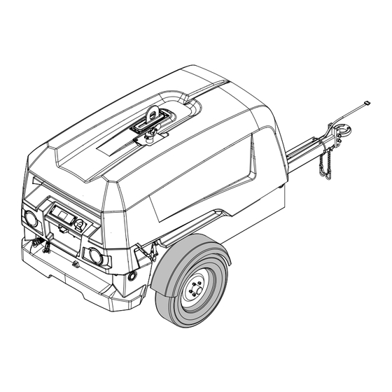
Page 23: Operating Instructions
DRAWBAR PREPARATIONS FOR TOWING Note: the pivoting feature of the drawbar is for Atlas Copco air compressor may be supplied to a customer shipping purpose only. The drawbar is to remain in with a folded drawbar. The drawbar is positioned in it’s the down position after it’s initial setup. -
Page 24: Parking Instructions
PARKING INSTRUCTIONS 1. Before initial start-up, prepare battery for operation if not already done. When parking a compressor, secure prop (1) or nose wheel 2. With the compressor standing level, check the level of to support the compressor in a level position. Place the the engine oil. -
Page 25: Starting / Stopping
STARTING / STOPPING EMERGENCY STOP Safety precautions Do not disconnect power supply to control box in any way when the control box is switched on. This will result in loss of controller data. Do not switch off the circuit breaker when the control box is switched on. -
Page 26: Controller Xc1004
CONTROLLER XC1004 CONTROL PANEL The controller is operated through local control panel. It has following functions: • Controls the compressor • Monitors the compressor Controls the compressor The controller controls the engine to reach the nominal working pressure. Monitors the compressor Several sensors are provided into the compressor. -
Page 27: Overview Screen Icons
OVERVIEW SCREEN ICONS Reference Name Start Button Start icon Load icon No load icon Enter/edit icon Stop Button Engine stop icon Power down icon Cancel/back icon Measurement Button Settings icon Up arrow icon Alarm Button Alarm Icon Down arrow icon - 27 -... - Page 28 Reference Name Reference Name Reference Name Measurement Icons Timer Icons Sensor circuit failure Engine rpm Engine resting Charge failure Requested engine rpm Engine preheat Overspeed alarm Vessel pressure Cooldown Coolant level Regulating pressure Purge timer Engine coolant temperature Status Icons Engine coolant temperature Regen needed Engine oil pressure...
- Page 29 Reference Name Reference Name Settings Menu Icons Overspeed test Pressure unit selection High vessel pressure test Temperature unit selection Safety valve test Diagnostic Mode Overrule ECU alarm Regeneration Initial overhaul reset Minor overhaul reset Major overhaul reset Running hours offset Download parameters Upload parameters E-stop counter...
-
Page 30: Starting
STARTING Press the start button to power up the compressor. STOPPING Press the start button to unload the compressor if a loading valve is installed. The ‘Engine stop’ icon indicates that the stop button is used to stop the engine. Let the engine cools down for few seconds. -
Page 31: View Types
VIEW TYPES Main View Alarm View Setting View The main view shows all the basic information: • Status icon • Fuel level indicator • Measurement • Running hours • Vessel pressure indicator • Activated alarms • Def indicator The start button is used to load/unload the compressor. The measurement button is used to change the measurements. - Page 32 Timer View Timer view is activated during: • Warming up • Cooling down • Preheat • Purging power down prevention - 32 -...
-
Page 33: Fault Codes
FAULT CODES ALARM CODE ALARM TEXT FAILCLASS ALARM CODE ALARM TEXT FAILCLASS 1500 INITIAL OVERHAUL ALARM WARNING 7009 ECU PROTECT LAMP WARNING 1521/1522 MINOR OVERHAUL WARNING 7020 ENGINE SPEED ALARM SHUTDOWN 1551/1553 COMPRESSOR OIL CHANGE WARNING 7030 ENGINE COOLANT TEMP CONTROLLED STOP 1552/1554 MAJOR OVERHAUL... -
Page 34: Maintenance
Maintenance USE OF SERVICE PAKS PREVENTIVE MAINTENANCE SCHEDULE For engine maintenance refer to Engine Operation Manual. Service Paks include all genuine parts needed for normal The schedule contains a summary of the maintenance maintenance of both compressor and engine. Service Paks instructions. - Page 35 Replace Inspections and Disclaimers Inspection by Atlas Copco Service Technician Inspect • 1: Included within Atlas Copco Service Kit • Failure to perform the maintenance will cause prob- • 2: When biodiesel fuel is used, change the fuel filter lems that will significantly degrade Machine and cartridge, fuel hose and clamp bands with new ones Engine performance.
-
Page 36: Oil Specifications
55 gallon 209 Liter) drum: 1310 6005 92 LUBRICATION OILS Engine coolant It is strongly recommended to use Atlas Copco branded PARCOOL - EG lubrication oils for compressor. Order number Compressor oil 1.3 gallon (5 Liter) pail:... -
Page 37: Oil Level Check
The pointer of the oil level ket contacts its seat, then tighten one half turn only. In this case, contact Atlas Copco. gauge (OLG) must register in the upper extremity of the Fill the air receiver until the pointer of the oil level green range. -
Page 38: Cleaning Coolers
In a separate Service Bulletin ELECTROLYTE (ASB), which may be obtained on request. Consult Atlas Copco. Read the safety instructions carefully. Electrolyte in batteries is a sulphuric acid solution in distilled water. Keep the coolers clean to maintain the cooling efficiency. -
Page 39: Adjustments And Servicing Procedures
Adjustments and servicing procedures ADJUSTMENT OF THE CONTINUOUS REGULATING SYSTEM - 39 -... -
Page 40: Air Filter Engine/Compressor
1. Start and warm up the engine. Reassemble in reverse order of dismantling. The Atlas Copco air filters are specially 2. With the outlet valves (AOV) closed, loosen the regu- Inspect and tighten all air intake connections. -
Page 41: Air Receiver
AIR RECEIVER FUEL SYSTEM The air receiver is tested according to official standards. Regularly have inspections carried out in conformity with local regulations. Replacing the filter element: 1. Unscrew the final filter element from the adapter head. 2. Clean the adapter head sealing surface. Lightly oil the SAFETY VALVE gasket of the new element and screw the latter onto All adjustments or repairs are to be done by... -
Page 42: Problem Solving
Have element removed and inspected by an Atlas copco Service representative. Air intake throttle valve remains partially closed. Check unloader and identify reason for open valve; if possible: solve; else: contact Atlas copco. Safety valve (SV) leaking. Remove and inspect. Replace if not airtight after reinstallation. - Page 43 Remove valve and check for proper opening and closing. Replace if out of order. Fan blade(s) broken. Check and correct if necessary. Oil separator element (OS) clogged. Have element removed and inspected by an Atlas copco Service representative. - 43 -...
-
Page 44: Technical Specifications
Technical specifications COMPRESSOR /ENGINE SPECIFICATIONS REFERENCE CONDITIONS Designation Unit XAS 188 CD Absolute inlet pressure 14.7 Relative air humidity °C Air inlet temperature °F Normal effective working pressure The inlet conditions are specified at the air inlet grating outside the canopy. LIMITATIONS Designation Remark... - Page 45 ALTITUDE UNIT PERFORMANCE CURVE - 45 -...
-
Page 46: Performance Data
PERFORMANCE DATA (133) Designation Remark Unit XAS 188 CD Engine shaft speed, normal 2450 Engine shaft speed, maximum 2800 Engine shaft speed, compressor unloaded 1600 Free air delivery (130) 100% FAD (full load) gal/hr 2.37 75% FAD gal/hr 1.92 Fuel consumption at 50% FAD gal/hr 1.69... -
Page 47: Design Data
DESIGN DATA COMPRESSOR UNIT Designation Unit All units Designation All units Number of compression stages Capacity of compressor oil system 4.76 ENGINE Net capacity of air receiver 18.02 Designation Unit XAS 188 CD Capacity of standard fuel tanks Make Caterpillar Type C2.2T Coolant... - Page 48 Your Atlas copco compressor consists for the most part of metallic materials, that can be remelted in steelworks and smelting works and that is therefore almost infinite recyclable.
- Page 49 Maintenance log Compressor Customer..................................................Serial number..................................................... Service hours Maintenance action Date By initials - 49 -...
- Page 50 Maintenance log Compressor Customer..................................................Serial number..................................................... Service hours Maintenance action Date By initials - 50 -...
- Page 52 www.atlascopco.com...
Need help?
Do you have a question about the XAS 188 CD S8 T4F HOP and is the answer not in the manual?
Questions and answers