Table of Contents
Advertisement
Instruction book
Atlas Copco Stationary Air Compressors
Instruction book
SF1 - SF2 - SF4 Skid -Tank-mounted
SF6 - SF8 Twin
SF6 - SF8 - SF11 - SF15 Multi
Copyright 2003, Atlas Copco Airpower n.v, Antwerp, Belgium.
Any unauthorized use or copying of the contents or any part thereof is prohibited. This applies in
particular to trademarks, model denominations, part numbers and drawings.
This instruction book meets the requirements for instructions specified by the machinery directive
98/37/EC and is valid for CE as well as non-CE labelled machines.
Note: The PED instructions for this machine are included at the end of the book.
No. 2920 1521 00
Registration code: APC SF / 38 / 980
2003-10
www.atlascopco.com
2920 1521 00
1
Advertisement
Table of Contents

Related Manuals for Atlas Copco Air Compressor


Summary of Contents for Atlas Copco Air Compressor
- Page 1 SF6 - SF8 Twin SF6 - SF8 - SF11 - SF15 Multi Copyright 2003, Atlas Copco Airpower n.v, Antwerp, Belgium. Any unauthorized use or copying of the contents or any part thereof is prohibited. This applies in particular to trademarks, model denominations, part numbers and drawings.
- Page 2 Atlas Copco. Follow all relevant safety precautions, including those mentioned on the cover of this book. Repairs must be carried out by trained personnel from Atlas Copco who can be contacted for any further information.
-
Page 3: Table Of Contents
Instruction book 1 LEADING PARTICULARS... 5 1.1 General description... 5 1.1.1 Compressor variants ... 5 1.1.2 Compressor elements (Fig. 1.1)... 5 1.2 Air flow ... 9 1.3 Cooling and condensate drain systems (Fig. 1.9) ... 9 1.4 Regulating system on SF Skid - Tank-mounted - Twin ... 10 1.5 Regulating system on SF Multi ... - Page 4 Instruction book 7.16 SF6-15 Multi 145 psi 60 Hz 1) ... 40 8 REGULATOR FUNCTIONS FOR SF MULTI ... 41 8.1 Menu-driven control programs... 41 8.1.1 Function of control programs ... 42 8.1.2 Main screen... 42 8.1.3 Calling up other menus ... 44 8.2 Quick look at actual compressor status ...
-
Page 5: Leading Particulars
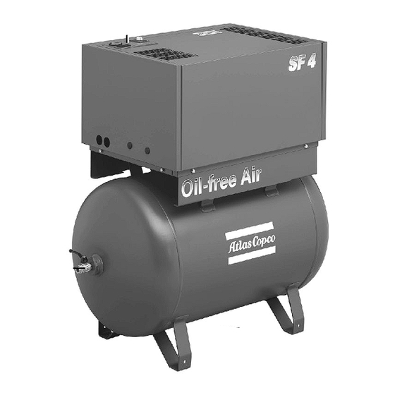
Instruction book 1 LEADING PARTICULARS 1.1 General description SF1 up to SF15 are stationary, oil-free compressors driven by an electric motor. 1.1.1 Compressor variants SF Skid (Fig. 1.2) The components of the compressor are housed in a bodywork with removable front/top panel. The compressor is mounted on a frame designed to allow easy installation at the required spot. - Page 6 Instruction book Fig. 1.2 SF4 Skid 1.3 SF4 Tank-mounted 2920 1521 00 Control panel Air outlet valve Control panel Air outlet valve...
- Page 7 Instruction book Fig. 1.4 SF Twin Elektronikon regulator Electric cabinet Air outlet valve Dryer (on Full-Feature) Compressor modules Emergency stop button Fig. 1.5 SF8FF Multi 2920 1521 00 Control panels Air outlet valve...
- Page 8 Instruction book Elektronikon regulator Electric cabinet Air outlet valve Dryer (on Full-Feature) Compressor modules Safety valve (ASME) Emergency stop button Fig. 1.6 SF15FF Multi Fig. 1.7 Details of a compressor module on SF Tank-mounted 2920 1521 00 Air filter Compressor element Air cooler Belts Safety valve...
-
Page 9: Air Flow
Instruction book Fig. 1.8 Details of a compressor module on SF Multi 1.2 Air flow Air is drawn through the air filter into the compressor modules and is compressed. Compressed air is discharged through the check valve and air cooler towards the air net. 1.3 Cooling and condensate drain systems (Fig. -
Page 10: Regulating System On Sf Skid - Tank-Mounted - Twin
Instruction book 1.4 Regulating system on SF Skid - Tank-mounted - Twin The air net pressure is kept within limits by a pressure switch mounted in the cabinet below the control panel (Fig. 1.10). The switch is connected to the air outlet and electrically connected in the circuit of the drive motor. -
Page 11: Regulating System On Sf Multi
The regulator has a built-in function to automatically restart the compressor if the voltage is restored after voltage failure. For compressors leaving the factory, this function is made inactive. If desired, the function can be activated. Consult Atlas Copco. 2920 1521 00... -
Page 12: Control Panel (Fig. 1.11)
Instruction book Fig. 1.11 Elektronikon regulator on SF Multi 1.5.5 Control panel (Fig. 1.11) To control the compressor and to read and modify programmable parameters, the regulator is provided with a control panel including: Designation Start button Display Scroll keys Tabulator key Function keys Voltage on LED... -
Page 13: Display - Keys
To delete compressor start/stop commands Extra To find the module configuration of the regulator Help To find the Atlas Copco internet address Limits To show limits for a programmable setting Mainscreen To return from a menu to the main screen... - Page 14 Instruction book Designation Function Menu Starting from the main screen, to have access to submenus Menu Starting from a submenu, to return to a previous menu Modify To modify programmable settings Program To program modified settings Reset To reset a timer or message Return To return to a previously shown option or menu Selecting a menu...
-
Page 15: Electric Cabinet On Sf Multi
Instruction book 1.6 Electric cabinet on SF Multi F1/8 Fuses Auxiliary contactor, dryer K21/24 Contactors Q21/24 Circuit breakers T1/2 Transformers Terminal strip, mains supply Terminal strip, dryer 1X3/6 Terminal strips Fig. 1.14 Electric cabinets, SF Multi 2920 1521 00... -
Page 16: Air Dryer On Sf Full-Feature (Fig. 1.15)
Instruction book 1.7 Air dryer on SF Full-Feature (Fig. 1.15) Compressed air circuit Wet compressed air enters heat exchanger (13) and is cooled by the outgoing, cold, dried air. Water in the incoming air starts to condense. The air then flows through heat exchanger (11) where the refrigerant evaporates and withdraws heat from the air. -
Page 17: Installation
Instruction book 2 INSTALLATION 2.1 Dimension drawings (Figs. 2.1 up to 2.5) 9820 4052 00/1 55100D Fig. 2.1 Dimension drawing, SF 1-4 Skid 9820 4053 00/1 55101D Fig. 2.2 Dimension drawing, SF 1-4 Tank-mounted 2920 1521 00... - Page 18 Instruction book Fig. 2.3 Dimension drawing, SF 6-8 Twin Text on Figs.2.1/2.3 Motor cooling air outlet Element cooling outlet Cooling air inlet Compressed air outlet 2920 1521 00 9820 4054 00/1 55102D Electrical supply Type Pressure Mass, approx.
- Page 19 Instruction book (15) (10) (11) (12) (14) (13) 9820 4027 00 55098D Fig. 2.4 Dimension drawing, SF 6-8 Multi 2920 1521 00...
- Page 20 Instruction book (16) (15) (10) (11) (12) (14) 9820 4026 00 (13) 55099D Fig. 2.5 Dimension drawing, SF 11-15 Multi 2920 1521 00...
- Page 21 Instruction book Text on Figs. 2.4/2.5 Electric cable Manual drain Automatic drain Compressor cooling air outlet Bodywork ventilation Aftercooler and dryer cooling air outlet Centre of gravity With dryer Without dryer (10) Dimensions +/- 10 mm (11) Weight (12) Weight +/- 10 kg (13) Compressor and bodywork cooling air inlet (14)
-
Page 22: Installation Proposal (Fig. 2.6)
Instruction book 2.2 Installation proposal (Fig. 2.6) Fig. 2.6 Installation proposal, SF Multi Text on Figs. 2.6 Minimum free area Compressor Ventilation proposals 2920 1521 00 9820 3960 00 55097D... - Page 23 Instruction book Install the compressor on a level floor, in a cool but frost-free room which is well-ventilated. The air should be clean. Position of compressed air outlet valve. The maximum total pipe length can be calculated as follows: 4/13 Ventilation: the inlet grids and fan for compressor room ventilation should be installed in such a way that any recirculation of cooling air to the compressor or dryer is avoided.
-
Page 24: Electrical Connections
Instruction book 2.3 Electrical connections General The electrical installation must correspond to the local codes. The mains supply and earthing lines must be of suitable size. See section 7.1. The installation must be earthed and protected by fuses in each phase. An isolating switch must be installed near the compressor. - Page 25 Instruction book SF Multi Connect the supply cable to terminals L1, L2 and L3 of terminal strip (1X0-Fig. 1.14), connect the neutral conductor to terminal (N) and the earthing conductor to the earthing bolt (1X3). (26) (25) (24) (23) (22) (21) (20) (19)
- Page 26 Instruction book Dryer (optional) F1/11 Fuses Auxiliary contactor, dryer K21/24 Contactors M1/4 Motors Fan motor, air cooler Fan motor, bodywork PT20 Pressure sensor, air outlet Q21/24 Circuit breakers Emergency stop button TSHH20 Temperature switch, air outlet protection TT11 Temperature sensor, compressor element 1 (lowest element) TT12 Temperature sensor, compressor element 2 TT13...
-
Page 27: Pictographs
Instruction book 2.4 Pictographs Fig. 2.9 shows examples of pictographs which may be used on the machine. Automatic condensate drain Manual condensate drain Switch off voltage and depressurize compressor before maintenance or repair Before connecting compressor electrically, consult Instruction book for motor rotation direction Torques for steel (Fe) or brass (CuZn) bolts Warning, voltage Consult Instruction book before greasing... -
Page 28: Operating Instructions
Outdoor/altitude operation If the compressor is installed outdoors or if the air inlet temperature can be below 0 °C, precautions must be taken. In this case, and also if operating at high altitude, consult Atlas Copco. Before initial start-up For SF Multi read section 8 to familiarize yourself with all regulator functions. -
Page 29: During Operation
Instruction book 3.3 During operation 3.3.1 Multi 1. If the automatic operation LED (8-Fig. 1.11) is alight, the regulator is automatically controlling the compressor modules (starting/stopping). 2. Check the readings on display (2-Fig. 1.11). In case of a warning or shut-down condition, see section 8.3. -
Page 30: Maintenance
When reaching the interval, a message will appear on the screen indicating which Service plans are to be carried out. After servicing, the intervals are to be reset. For detailed information, consult section 8.3. Important Always consult Atlas Copco in case any timer setting should be changed. 2920 1521 00... - Page 31 Operation Drain condensate On SF Full-Feature, check dewpoint Inspect air filter Check pressure drop over Atlas Copco filters (optional) Operate safety valve Clean compressor On SF Full-Feature, brush or blow off the finned surface of the condenser On SF Full-Feature, clean condensate trap...
-
Page 32: Adjustments And Servicing Procedures
In case of two belts, the belts must be replaced as a set, even if only one of them seems worn. Use Atlas Copco belts only. The part number of the belt set is mentioned in the Parts list. 1. Loosen motor hold-down bolts (3). -
Page 33: Safety Valve
Testing The valve can be tested on a separate compressed air line. If the valve does not open at the pressure marked on the valve, consult Atlas Copco. Warning No adjustments are allowed. Never run the compressor without safety valve. -
Page 34: Problem Solving
Instruction book 6 PROBLEM SOLVING Before carrying out any maintenance or repair: Stop the compressor, switch off the voltage and open the isolating switch. Close the air outlet valve (2-Figs. 1.2/1.4 or 3-Figs. 1.5/1.6) and open the manual drain valve: valve (1-Fig. -
Page 35: Principal Data
Instruction book 7 PRINCIPAL DATA 7.1 Electric cable size for SF1-8 Frequency Voltage 50 Hz 230 V 50 Hz 400 V 60 Hz 380 V 50 Hz 500 V CSA/UL 60 Hz 200/230 V 60 Hz 440/460 V 7.2 Electric cable size for SF 6-15 Multi Frequency Voltage 50 Hz... -
Page 36: Overload Relays For Sf1-8
Instruction book 7.3 Overload relays for SF1-8 Frequency Voltage 50 Hz 230 V 50 Hz 400 V 60 Hz 380 V 50 Hz 500 V CSA/UL 60 Hz 230 V 60 Hz 440/460 V Note: SF6 Twin have compressor modules of a different size, the first value is valid for the smaller SF2 module and the second one is valid for the bigger SF4 module 7.4 Overload relays for SF6-15 Multi Frequency... -
Page 37: Main Fuses For Sf1-8
Instruction book 7.5 Main fuses for SF1-8 Frequency Voltage 50 Hz 230 V 50 Hz 400 V 60 Hz 380 V 50 Hz 500 V CSA/UL 60 Hz 230 V 60 Hz 440/460 V 7.6 Main fuses for SF6-15 Multi Frequency Voltage 50 Hz... -
Page 38: Sf1-4 8Bar 50 Hz 1)
Instruction book 7.8 SF1-4 8bar 50 Hz 1) Compressor type Maximum working pressure Nominal working pressure Air temperature at outlet valve (Tank- mounted/Twin), approx. Air temperature at outlet valve (Skid), approx. Motor shaft speed Shaft input Sound pressure level 7.9 SF2-4 10 bar 50 Hz 1) Compressor type Maximum working pressure Nominal working pressure... -
Page 39: Sf6-15 Multi 8 Bar 50 Hz 1)
Instruction book 7.12 SF6-15 Multi 8 bar 50 Hz 1) Compressor type Maximum working pressure for SF Pack Maximum working pressure for SF Full-Feature Nominal working pressure Air temperature at outlet valve for SF Pack, approx. Air temperature at outlet valve for SF Full-Feature, approx. Motor shaft speed Shaft input Sound pressure level... -
Page 40: Sf6-15 Multi 125 Psi 60 Hz 1)
Instruction book 7.15 SF6-15 Multi 125 psi 60 Hz 1) Compressor type Maximum working pressure for SF Pack Maximum working pressure for SF Full-Feature Nominal working pressure Air temperature at outlet valve for SF Pack, approx. Air temperature at outlet valve for SF Full-Feature, approx. -
Page 41: Regulator Functions For Sf Multi
Instruction book 8 REGULATOR FUNCTIONS FOR SF MULTI 8.1 Menu-driven control programs To facilitate programming and controlling the compressor, menu-driven programs are implemented in the electronic module. A simplified menu flow is shown in Fig. 8.1. Fig. 8.1 Menu flow SF15 Workplace Full-Feature 2920 1521 00... -
Page 42: Function Of Control Programs
Instruction book 8.1.1 Function of control programs Program/Function Main screen Status data Measured data Counters Test Modify parameters Service Saved data 8.1.2 Main screen When the voltage is switched on, the Main screen is shown automatically, showing in short the operation status of the compressor. - Page 43 Stop the compressor. Switch off the voltage and depressurize the compressor. Check the sensor wiring. Replace the sensor or transducer, if necessary. Indicates that the compressor is set in remote control. Consult Atlas Copco. See section 1.5.7. Indicating the status of each compressor module...
-
Page 44: Calling Up Other Menus
Line 2 indicates whether the regulator operates in local control, remote control or LAN control mode: "Local control" means that the start/stop buttons on the keyboard are activated. "Remote control" means that these functions are controlled remotely. Consult Atlas Copco. “LAN control” means that the compressor can be controlled by an ES controller. -
Page 45: Status Data Menu
Instruction book 8.3 Status data menu The status data submenu gives information regarding the status of the compressor protection functions (shut-down, service warning and warning) and allows resetting of a shut-down and service condition. Procedure Starting from the Main screen (see section 8.1.2): Press the key "Menu"... -
Page 46: A Warning Message Exists
Instruction book 2. It remains possible to scroll through other menus, e.g. to check the values of other parameters. When returning to the Status data menu, the option "Shutdowns" will blink. This option can be selected by pressing the tabulator key (5) to return to the shut-down screen (Fig. 8.6). Shut-down reset 1. -
Page 47: A Service Warning Message Exists
Instruction book 8.3.4 A service warning message exists 1. LED (7) is alight and the main screen will change into a screen similar to that shown in Fig. 8.9. Compressor Outlet Menu 2. The indicators (***) are blinking and the service warning message appears alternately with the messages indicating whether the compressor is in operation or not (Compressor Running or Compressor Off). -
Page 48: Counters Menu
Instruction book 2. By pressing the ↓ key, a number of actually measured data can be found (see Fig. 8.1). 3. If one of the sensors is linked to a shut-down, service or warning function, both the actually measured value as well as the corresponding shut-down, warning or service level can be called up by pressing the tabulator key (5). -
Page 49: Modify Parameters Menu
Instruction book 8.7 Modify parameters menu Function The menu allows the operator to program: Parameters, see section 8.8. Protections settings, see section 8.9. Service plan settings, see section 8.10. Clock function settings, see section 8.11. Configuration settings, see section 8.12. 8.8 Modifying parameters Function To modify a number of parameters as mentioned below and in Fig. -
Page 50: Modifying The Pressure Bands
Instruction book 8.8.1 Modifying the pressure bands If desired, the operator can program two pressure bands (band 1 and band 2) with different pressure settings. The settings for band 1 are indicated as "Pressure Band 1 High" and "Pressure Band 1 Low", the settings for band 2 are indicated as "... -
Page 51: Modifying Protection Settings
Instruction book 8.9 Modifying protection settings Function 1. To modify protection settings: warning ("Warning"), e.g. Dryer LAT (Low Ambient Temperature) on Full-Feature machines 2. To check some compressor conditions, e.g. the status of the motor overload contacts per compressor module. The list of parameters is shown in Fig. 8.1. Note Some parameters cannot be modified. -
Page 52: Modifying Protections For Dryer Lat On Full-Feature Machines
Instruction book 8.9.2 Modifying protections for Dryer LAT on Full-Feature machines 1. Consult the section above to select the parameter Dryer LAT (Low Ambient Temperature): Dryer LAT Warning Back 2. The screen shows that the Dryer LAT is 10 °C and that the shut-down setting is 25 °C. To modify this setting, press the key "Modify"... - Page 53 Instruction book Important Always consult Atlas Copco in case any timer setting should be changed. The intervals must not exceed the periods below and must coincide logically. Programmed service plan intervals Service plans Service plan I Service plan A Service plan B...
-
Page 54: Programming Clock Function
Instruction book 4. Press the tabulator key (5): a screen similar to the one below will appear: Service Timer Level Menu 5. The screen indicates that the level for Service plan A is set at 5000 running hours. 6. Press the "Modify" key. The key "Limits" (F2) can be used to find the limitations for the parameter. Use the ↓... - Page 55 Instruction book 3. Press the tabulator key (5), following screen appears: Monday Tuesday Wednesday Back 4. Use the ↓ or ↑ key until the day on which a command must be programmed is followed by a right pointing arrow. Press the tabulator key (5), following screen appears: --:-- --:-- --:--...
-
Page 56: To Activate/Deactivate The Timer
Instruction book 8.11.2 To activate/deactivate the timer 1. Starting from the Main screen (see section 8.1.2): press the key "Menu" (F1) press the ↓ key until the option "Modify parameters" is followed by a horizontal arrow press the tabulator key (5) to activate the menu 2. -
Page 57: To Add A Command
Instruction book 2. Use the ↓ key to scroll until the option "Clock function" is followed by a horizontal arrow. Press the tabulator key (5), following screen appears: Clock Function Menu 3. Press the tabulator key (5), following screen appears: Monday Tuesday Wednesday... -
Page 58: To Delete Commands
Instruction book Suppose the command to stop the compressor at 18:00 must be added to the list of Monday: - 06:15 start - 06:15 pressure band 1 3. Press the tabulator key (5), following screen appears: Monday Tuesday Wednesday Menu 4. -
Page 59: Configuration Menu
Instruction book 2. Use the ↓ key to scroll until the option "Clock function" is followed by a horizontal arrow. Press the tabulator key (5), following screen appears: Clock Function Menu Deleting all commands Press the key "Delete" (F3) in the screen above. A question to confirm the deleting operation will appear. -
Page 60: Programming Compressor Control Modes
8. Proceed in a similar way for the other parameters to be modified. 8.12.1 Programming compressor control modes Compressor control modes The compressor can be controlled locally, remotely or via a local area network (LAN – consult Atlas Copco). Procedure 1. - Page 61 Instruction book Service plans Contact your Atlas Copco customer centre for the service actions related to these plans. Consult section 8.10 if any modification to the intervals should be required. When the service plan interval is reached, a message will appear on the screen. See section 8.3.
- Page 62 Instruction book 3. Press the tabulator key (5): Next Timer Level Back The screen shows that the next service plans to be carried out are plans A, B and I and that these plans are to be carried out each 10000 running hours. 4.
-
Page 63: Saved Data Menu
Instruction book 8.14 Saved data menu Function To call up some compressor data saved by the regulator. These data are: Last shut-down data Last emergency stop data Procedure 1. Starting from the Main screen (see section 8.1.2): press the key "Menu" (F1) press the ↓... -
Page 64: Programmable Settings
Instruction book 8.15 Programmable settings 8.15.1 Regulation settings Number of motor starts Minimum stop time 1) Stop between 2 compressor modules Start between 2 compressor modules Power recovery time 3) Delay at restarting after power recovery 3) Minimum pressure 2) 8 bar Pack 8 bar Full-Feature 10 bar Pack... -
Page 65: Service Settings
10 and 3600 seconds. A delay at restarting can also be programmed, allowing e.g. compressors to be restarted one after the other. To activate the automatic restart function, consult Atlas Copco. 4) Full-Feature version is the Pack version with integrated air dryer. - Page 66 Make sure that the vessel is complete with suitable and appropriate safety and control fittings and replace them with new Atlas Copco ones (consult the parts list) if necessary. The safety valve must be fitted directly to the vessel and the discharge capacity should be higher than the air intake of the compressor.
- Page 67 Instruction book Notes: 2920 1521 00...
- Page 68 Instruction book Notes: 2920 1521 00...
-
Page 69: Safety Precautions
Capacity ........... Atlas Copco air dryer instruction book: ...... - Page 70 .
Need help?
Do you have a question about the Air Compressor and is the answer not in the manual?
Questions and answers