
Related Manuals for Atlas Copco PTS 800 T3 Cud


Summary of Contents for Atlas Copco PTS 800 T3 Cud
- Page 1 Instruction Manual Instruction Manual for Portable Compressors English PTS 800 Cud T3 APP QSB 6.7...
- Page 3 PTS 800 Cud T3 APP Instruction Manual for Portable Compressors Instruction manual .................. 5 Circuit diagrams ..................93 Original instructions Printed matter N° 2954 9840 00 ATLAS COPCO - PORTABLE ENERGY DIVISION www.atlascopco.com 10/2016...
- Page 4 While every effort has been made to ensure that the information in this manual is correct, Atlas Copco does not assume responsibility for possible errors. Copyright 2016, Atlas Copco Airpower n.v., Antwerp, Belgium. Any unauthorized use or copying of the contents or any part thereof is prohibited.
-
Page 5: Table Of Contents
Congratulations on the purchase of your Atlas Copco compressor. It is a solid, safe and reliable machine, built according to the latest technology. Follow the instructions in this booklet and we guarantee you years of trouble-free operation. Please read the following instructions carefully before starting to use your machine. - Page 6 5.2.9.4 Set Language........54 Adjustment and servicing Engine consumable specifications .72 procedures ........64 5.2.9.5 Set Units ...........54 6.5.1 Engine fuel specifications....72 6.4.1 Coolant ..........64 5.2.9.6 Change Display Settings ....54 6.5.2 Engine oil specifications ....72 6.4.1.1 Coolant level check ......64 5.2.9.7 Go To Diagnostics......54 6.5.2 Engine oil specifications ....72 6.4.1.2 Replacing the coolant ......64...
- Page 7 Technical specifications ... 86 10.1 Torque values........86 10.2 Settings of shutdowns and safety valves........86 10.3 Compressor/engine specifications........87 10.4 Dimension drawing ......90 10.5 Conversion list of SI units into British units ........91 10.6 Data plate .........91 - 7 -...
-
Page 8: Safety Precautions For Portable Compressors
An operator is trained in all aspects of operating the unit The policy of Atlas Copco is to provide the users of their unsafe operating conditions. Take necessary steps to with the push-buttons, and is trained to know the safety equipment with safe, reliable and efficient products. - Page 9 The manufacturer does not accept any liability for any Normal ratings (pressures, temperatures, speeds, 13 In the event the safety labels are damaged or damage arising from the use of non-original parts and for etc.) shall be durably marked. destroyed, they must be replaced to ensure operator modifications, additions or conversions made without safety.
- Page 10 To tow a unit use a towing vehicle of ample 10 Never leave a load hanging on a hoist. Safety during transport and capacity. Refer to the documentation of the towing 11 A hoist has to be installed in such a way that the installation vehicle.
- Page 11 13 Never refill fuel while the unit is running, unless people entering the room, for even relatively be safeguarded with a safety cable, attached next to otherwise stated in the Atlas Copco Instruction short times, about the need to wear ear the valve.
- Page 12 Insulation or safety guards protecting these parts or dust, the respiratory organs must be protected and Parts shall only be replaced by genuine Atlas Copco shall not be removed before the parts have cooled depending on the nature of the hazard, so must the replacement parts.
- Page 13 14 Use only lubricating oils and greases recommended 20 When hot parts have to be handled, e.g. shrink undertaking major overhaul on it, prevent all or approved by Atlas Copco or the machine fitting, special heat-resistant gloves shall be used movable parts from rolling over or moving.
- Page 14 When connecting an auxiliary battery (AB) in Tool applications safety parallel to the unit battery (CB) with booster cables: Use the proper tool for each job. With the knowledge of connect the + pole of AB to the + pole of CB, then correct tool use and knowing the limitations of tools, connect the - pole of CB to the mass of the unit.
-
Page 15: About This Manual
User Interface Max. working pressure setpoint Technician Atlas Copco personnel allowed to setpoint calibrated in the Pc4003™ change settings of the control and At this max. setpoint the engine This... -
Page 16: Main Parts
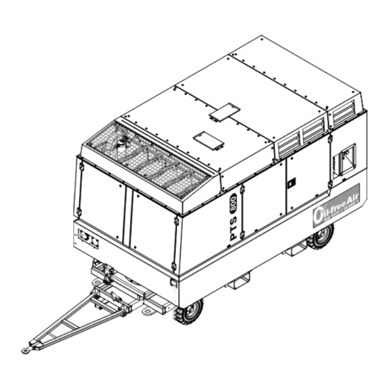
General description The PTS 800 T3 Cud is a portable, two-stage screw compressor unit, which delivers oil-free air. The PTS 800 T3 Cud is built for a nominal effective working pressure of 6.9-10.3 bar (100-150 psi). An overview of the main parts is given in the diagram below. - Page 17 Aftercooler Air intake filter (compressor) Air intake filter (engine) Battery Blow-off silencer Battery switch Cubicle (battery charger, heaters, spare I/O’s) Charge air cooler LP compressor element HP compressor element Control unit Engine Cooling fan Filler cap coolant Filler cap fuel Fuel filter engine Primary coarse fuel filter / Water separator Fuel level sensor...
-
Page 18: Markings
Markings Atlas Copco labels its products with ISO defined and other safety markings providing instructions and Rotation direction Do not stand on outlet valves information. The markings also warn of hazards. For convenience and safety, keep all markings in legible condition, replacing them when damaged or missing. - Page 19 16 A 1638 1041 00 Instruction label for remote Label sockets US+ heaters 110 VAC emergency stop 16 A Atlas Copco engine oil PAROIL 24 VDC 32 A E Mission Green 1638 1820 00 Atlas Copco engine oil PAROIL PAROIL E...
-
Page 20: Mechanical Features
The male rotors have four lobes and the female rotors Mechanical features 3.3.5 Speed regulation and unloading six flutes. Thus, the male rotors revolve at 1 1/2 times system the speed of the female rotors. The absence of contact 3.3.1 Engine The regulation of the unit is governed by the Engine between the rotors and between the rotor crests and Control Module (ECM) and the Compressor Control... -
Page 21: Bodywork
After activation of the system always contact Atlas connected to an external fuel tank. Copco immediately to investigate and repair the The PTS 800 T3 Cud provides an oil tank (20 l) for machine. automatic oil filling (1). When the oil level of the 3.3.11 Inlet shutdown valve... -
Page 22: Cold Start (Option)
3.3.14 Cold start (option) The cold start option consists of a heating kit, making sure that the engine starts at temperatures as low as -25°C (-13°F). The heating kit consists of heater sockets (see also chapter “Sockets EU” and “Sockets USA”), an oil temperature sensor and heater plugs that are mounted on the water separator, the gearbox and the engine block. -
Page 23: Hot Air Outlet
3.3.15 Hot air outlet This option gives the opportunity to obtain hot compressed air. Three different air outlet settings are possible: To obtain cold air: – open air outlet valve (1), – close flanges hot air outlet and hot air inlet (4, 3), –... - Page 24 To obtain hot air, without cold air: – close air outlet valve (1), – open hot air outlet flange (4), – keep hot air inlet flange closed (3), – open hot air outlet valve (2). Close valve Open valve Open flange Close flange - 24 -...
- Page 25 To obtain cold and hot air: – open air outlet valve (1), – close hot air outlet valve (2), – open hot air outlet flange (4), – open hot air inlet flange (3). Close valve Open valve Open flange Close flange - 25 -...
- Page 26 Components Air outlet valve (AOV) Hot air outlet valve Hot air inlet flange Hot air outlet flange - 26 -...
-
Page 27: Electrical Features
– Battery charger EEC/AUS: 240 VAC / 24 VDC - 100 VA – Battery charger USA: 120 VAC / 24 VDC - The PTS 800 T3 Cud EU variant is equipped with the 100 VA following sockets: For more detailed info on the battery charger, see also section “Maintaining the battery voltage”. -
Page 28: Sockets Usa
The PTS 800 T3 Cud is equipped with the following 3.4.5 Sockets USA 3.4.6 Fuse box circuit breakers: General circuit breaker (15A) Circuit breaker 24V outlet (30A) Circuit breaker fire extinguisher (10A) Circuit breaker ECM (30A) Circuit breaker inlet shutdown valve (4A,... -
Page 29: Heater Box
When Remote Emergency Stop is NOT required (factory setting) – Install the bridge between the terminals Install bridge The PTS 800 T3 Cud is equipped with the following circuit breakers for the heaters: Internal E-stop Circuit breaker heater EU/battery charger... - Page 30 When Remote Emergency Stop is required The emergency stop is to be used for (customer setting) stopping the machine immediately – Remove the bridge between the terminals in case of an emergency or risk of human injuries. It is NOT intended as the normal stop procedure.
-
Page 31: Operation Flows
Operation flows An air-operated balancing piston is fitted behind the 3.5.1 Air flow system male rotor rear thrust bearing of HP compressor Description element. The piston decreases the load on the male rotor front thrust bearing during loaded operation. Air drawn through the air intake filters (AF ), and During loading the HP compressor element balancing unloader (UA) into LP compressor element (CE... - Page 32 Overview Aftercooler Air intake filter (compressor) Air filter switch Air outlet valve Blow-off silencer Blow-off valve By-pass valve Chamber (unloader assembly) Chamber (unloader assembly) LP compressor element HP compressor element Check valve Diaphragm (unloader assembly) Intercooler Loading solenoid valve Membrane (unloader assembly) Pc4003 Intercooler relief valve Air outlet silencer (HP compressor element)
-
Page 33: Cooling And Lubricating Oil System
3.5.2 Cooling and lubricating oil system Description Oil from the oil sump (OS) of gear casing (GC) is Bypass valve (BV ) opens when the pressure rise circulated by an oil pump (OP), mounted on the front over the oil cooler is above normal. This will happen of the gear casing. - Page 34 Overview Bypass valve (oil cooler) Bypass valve (oil filter) LUBRICATING CIRCUIT Bypass valve (oil sump) LP compressor element HP compressor element Cooling fan (RAD, IC, AC, OC, CAC) Gear casing Oil cooler Compressor oil filter (with bypass valve) Oil pump Oil sump Pressure sensor Temperature sensor...
-
Page 35: Fuel System
3.5.3 Fuel system Description In case of internal fuel supply, fuel from the fuel tank (FT) is circulated by the engine fuel pump (FP ). The fuel is pumped through a 3-way valve (TWV) to the primary coarse fuel filter (FF The fuel then passes through the engine fuel filter ) and enters the engine (E). - Page 36 Overview Bypass valve Filler cap (fuel tank) Check valve Engine External fuel supply coupling Fuel filter engine Primary coarse fuel filter / water separator Fuel tank 3-way valve fuel selector in horizontal position (internal) fuel selector in vertical position (external) - 36 -...
-
Page 37: Coolant System
3.5.4 Coolant system Overview Engine Cooling fan (RAD, IC, AC, OC, CAC) Radiator Top tank (radiator) Engine coolant pump (radiator) Description The coolant system contains a coolant flow to cool the engine’s cylinders. The coolant is circulated by the engine coolant pump ), seated on the front of the engine (E). -
Page 38: Installation
Installation 4.1.2 Lifting The operator is expected to apply all relevant safety precautions, To lift the unit, use a lift truck or crane with sufficient including those mentioned capacity (wet weight of unit is 4960 kg (17,552 lbs)). pages 7-10 of this book. Use the lifting positions of the unit as shown in the figure below. -
Page 39: Parking
Parking – Locate the wind direction and place the rear end of – Place wheel chocks (1) in front of and behind the – Lock the towbar (3) in the raised position with the the unit upwind, away from contaminated wind wheels or apply the parking brake (2) before the catcher (4). -
Page 40: Operating Instructions
Operating instructions – Move the power switch on the control unit (CU) to Checks before starting Make sure that nobody is in the unit the ON position and read the fuel level on the and all doors are closed prior to –... -
Page 41: Operating And Setting The Pc4003™ Controller
Operating and setting the LOAD button. BACK button Pc4003™ controller Pressing this button will: Moves back one level or ignores the change. – initiate Auto Load 5.2.1 Pc4003™ button overview function, or commands the compressor to load (depending on actual status). –... -
Page 42: Pc4003™ Display Icons
5.2.2 Pc4003™ display icons Primary Main view View, Overhaul, Auto load, Preset, Active operation mode indication Active compressor status Navigation: toggle between main view and engine view Regulator overrule indication Regulator pressure value or info text Set active pressure setpoint Alarm indication and compressor info MAIN VIEW Main view indication... - Page 43 ALARM OIL FILL OVERHAUL Active and not-acknowledged Shutdown Major Overhaul required. The engine oil level as dropped under a Alarm. set level. The oil fill pump will be AUTO LOAD activated. ALARM This icon will be shown if the Auto Load Active and not-acknowledged Non- functionality is enabled, or by means of a Shutdown Alarm.
- Page 44 Secondary Main view - Engine view View, Overhaul, Auto load, Preset, Active operation mode indication Active compressor status Navigation: toggle between main view and engine view Engine info Alarm indication and compressor info MAIN VIEW ENGINE WARNING LAMP - AMBER LED steady on: low alarm LOADED LED flashing slow: medium alarm...
-
Page 45: Possible Views
5.2.3 Possible views Setup view Alarm view Main view ALARMS SETTINGS LOADED LOADED MAIN VIEW READY TO START 3450 BATTERY LOW ALARM 1000 GENERAL SETTINGS 2070 COOLANT LEVEL LOW 2000 DIGITAL INPUTS 3010 FUEL LEVEL LOW 3000 VOLTAGE INPUTS ECU DM1 LIST 4000 TEMPERATURE INPUTS ECU DM2 LIST 5000 RELAY OUTPUTS... -
Page 46: Operations Overview
Measuring view 5.2.5 Starting Except for a controller power down, nothing interrupt 1. Switch on the battery switch. MEASUREMENTS INITIALIZING SEQUENCE. 2. Switch on the machine by switching the Pc4003™ During INITIALIZING LOADED Power Switch to the ON position. SEQUENCE, all buttons / inputs / While the machine gets powered up, the controller outputs / alarms are inactive. - Page 47 The following view is shown. 3. Press the START button. MAIN VIEW The machine activates its horn and flasher light MAIN VIEW for 5 seconds, to notify that it is starting. ENGINE PREHEATING READY TO START MAIN VIEW READING ENGINE DATA 1286h --RPM 0.0 bar...
- Page 48 The engine starts cranking. The engine starts running at idle speed. MAIN VIEW MAIN VIEW MAIN VIEW ENGINE RESTING ENGINE WARMING UP ENGINE CRANKING 120s 13°C 40°C 25°C 300s 0RPM 800RPM 324RPM 1286h 324RPM 0.0 bar 1286h 1200RPM 3.3 bar 1286h 324RPM 0.0 bar...
- Page 49 If during the WARMING UP SEQUENCE, all After warming up, the machine is ready to be conditions are met to end the WARMING UP loaded and is waiting for a load command. MAIN VIEW SEQUENCE, WARMING ENGINE WARMING UP SEQUENCE blocked MAIN VIEW TEMPERATURE CONTROL function, the...
-
Page 50: Stopping
4. Press the LOAD button. 5.2.6 Stopping Active Buttons: Press the STOP button. Stop Button MAIN VIEW The engine will go into COOLDOWN SEQUENCE. (to initiate Stop command) The following view is shown. PREPARING TO LOAD Load Button (to activate Automatic Load) MAIN VIEW Measurement View Button ENGINE COOLING DOWN... - Page 51 Following condition is taken into account, before the During the COOLDOWN SEQUENCE, if the After cooling down, the engine enters the STOP COOLDOWN SEQUENCE ended: COOLDOWN ‘MODE’ is set to ‘timer based’, or if SEQUENCE. During the STOP SEQUENCE, before COOLDOWN TIMER ≥...
-
Page 52: Shutdown
When the controller is waiting for the STOP 5.2.7 Shutdown 5.2.8 Power off DETECTION ‘MINIMUM START DELAY’ to When the machine is shut down due to a critical alarm The compressor is equipped with a battery switch. elapse, an additional timer is shown on the display: or an emergency stop, the following view is shown. -
Page 53: Settings
As soon as the fuel level is higher than the warning 5.2.9 Settings 5.2.9.2 Acknowledge an Alarm level again, the alarm icon will automatically If an alarm becomes active, for example a Low Fuel For buttons to be used see section “Pc4003™ button disappear. -
Page 54: Set Language
8. Now press BACK until you are back in the Main 5.2.9.4 Set Language 5.2.9.6 Change Display Settings View (or in the menu you require). 1. Press the SETTINGS VIEW button. 1. Press the SETTINGS VIEW button. 9. To leave Diagnostics, press the STOP button. 2. - Page 55 7. Set the desired time schedule (default = 5 minutes) 5.2.9.9 Overrule ECU Alarms and press ENTER. If the Overrule ECU Alarms function is enabled, the Pc4003™ controller will temporarily ignore all 8. Now press BACK until you are back in the Main received ECU alarms.
-
Page 56: Operating The Automatic Fire Suppression System
Operating the automatic fire suppression system 5.3.1 Main components Control box Cylinder with extinguishing fluid Nitrogen cylinder Heat sensitive wire Nozzles Automatic actuator Alarm horn Flash light - 56 -... - Page 57 5.3.2 Operation 5.3.3 Daily check The fire suppression system is equipped with an The LED’s status on the control box should be automatic activation. checked daily prior to starting up the compressor. The green Power LED (1) should flash every three The automatic activation detects a fire via a heat seconds! It is not allowed to start up the compressor sensitive wire (4).
-
Page 58: Maintenance
Maintenance Maintenance schedule every every every every every every every Maintenance schedule Daily 500 hrs or 1000 hrs or 5000hrs or 50 hrs 3000hrs 6000 hrs 10000 hrs 6 months yearly 4 years Service pack 2912 4584 05 2912 4585 06 Engine Check engine oil level / Add engine oil Change engine oil (2) - Page 59 every every every every every every every Maintenance schedule Daily 500 hrs or 1000 hrs or 5000hrs or 50 hrs 3000hrs 6000 hrs 10000 hrs 6 months yearly 4 years Service pack 2912 4584 05 2912 4585 06 Check crankcase breather tube Compressor Check compressor oil level Change compressor oil...
- Page 60 every every every every every every every Maintenance schedule Daily 500 hrs or 1000 hrs or 5000hrs or 50 hrs 3000hrs 6000 hrs 10000 hrs 6 months yearly 4 years Service pack 2912 4584 05 2912 4585 06 Check fire extinguisher system (see Dafo manual) Test engine air inlet shutdown valve Clean spark arrestor...
-
Page 61: Use Of Preventive Maintenance Schedule
It guarantees that all necessary parts are replaced at lifting eye, the towbar and the axle the same time which improves the uptime of the unit. securely tightened. Atlas Copco service kits offer you all the benefits of Refer section “Technical genuine Atlas Copco parts, save on administration specifications”... -
Page 62: Engine Maintenance Procedures
– To drain oil from system, open the oil filler cap, Engine maintenance Compressor maintenance remove the drain plug, located at the right-hand procedures procedures side under the unit and open the drain cock (1). Refer to the engine’s operator manual for full –... -
Page 63: Compressor Oil And Oil Filter Change
6.3.3 Compressor element overhaul change When a compressor element is due for overhaul, it is recommended to have it done by Atlas Copco. This guarantees the use of genuine parts and correct tools with care and precision. – Remove the oil filter (2), e.g. by means of the handle of a spanner in the slot at the top. -
Page 64: Coolant Level Check
Drain – Using the Atlas Copco Instruction book, determine the amount of PARCOOL EG required and pour into the radiator top tank. – It should be clearly understood that proper cleaning reduces contamination risks. -
Page 65: Main Parts
6.4.2 Air filter 6.4.2.2 Cleaning the dust trap The Atlas Copco air filters are To remove dust from the dust trap pinch the vacuator specially designed 6.4.2.1 Main parts valve (6) several times. application. The use of non-genuine air filters may lead to severe damage 6.4.2.3 Replacing the air filter element and... -
Page 66: Cleaning The Filter Element
– Reassemble in reverse order of dismantling. 6.4.3 Fuel system – Inspect and tighten all air intake connections. 6.4.3.1 Draining fuel filters 6.4.2.4 Cleaning the filter element – Withdraw the filter element (see section 6.4.2.3). Reinstall the dust trap cover to protect the air intake system while cleaning the element. -
Page 67: Priming The System
6.4.3.2 Priming the system 6.4.3.3 Cleaning fuel tank 6.4.4 Cleaning coolers – Check to make sure the drain valve at the base of Keep all coolers clean to maintain the cooling the fuel filter is closed. efficiency. The fan side surface of the radiator, intercooler, –... -
Page 68: Poly V-Belt Tension Adjustment
Correct the V-belt tension by loosening the fixing 6.4.5 Poly V-belt tension adjustment Protect the electrical and controlling screw (1) of V-belt tensioner (2). Loosen the lock nut equipment, air filters, etc. against To check the cooler fan poly V-belt tension, measure on the adjusting screw (3). -
Page 69: Lp And Hp Safety Valve Adjustment
6.4.6 LP and HP safety valve All adjustments and repairs and adjustment following checks must be done by an authorized representative of the valve supplier. – A check of the opening of the lifting gear, once a year. – A check of the set pressure once a year according to the local regulations. -
Page 70: Electrolyte
– Rock the battery a few times so that possible air 6.4.7 Battery care 6.4.7.4 Maintaining the battery voltage bubbles can escape; wait 10 minutes and check the To maintain the battery voltage, use the unit’s Before handling batteries, read the level in each cell once more;... -
Page 71: Servicing Water Separator
Maintenance must be performed by authorized personnel only. Please contact Atlas Copco. All maintenance activities are to be recorded in a logbook. - 71 -... -
Page 72: Engine Consumable Specifications
Specifications PAROIL The viscosity grade should correspond to the ambient PAROIL has an excellent Total Base Number (TBN) PAROIL from Atlas Copco is the ONLY oil tested temperature and ISO 3448, as follows. retention and more alkalinity to control acid and approved for use in all engines built into Atlas formation. -
Page 73: Engine Coolant Specifications
Atlas Copco PAROIL E Mission Green is currently in use in Atlas Copco compressors and The system may be under pressure. -
Page 74: Checks And Trouble
PARCOOL EG Checks and trouble Battery and alternator precautions shooting Order Liter cu.ft number – Never reverse the polarity of the battery or the Problem solving chart alternator. 0.175 1604 5308 01 The chart helps to solve mechanical and electrical –... -
Page 75: Trouble Shooting
Trouble shooting Symptom Possible cause Corrective action Compressor loaded automatically Loading solenoid valve stuck in loaded position. Remove and check loading solenoid valve. to full capacity after starting Replace valve if necessary. Air intake throttle valve in open position. Check position throttle valve. Disconnect loading solenoid valve from throttle valve housing and connect independent compressed-air line to throttle valve housing. - Page 76 Replace valve, if necessary. Compressor element(s) not in order. Check interstage pressure and have compressor element(s) inspected by Atlas Copco. Air intake throttle valve remains partially closed. Disconnect loading solenoid valve from throttle valve housing and connect independent compressed-air line to throttle valve housing.
- Page 77 Move unit away from walls; when banked with other units, leave space between them. Oil cooler clogged externally. Clean oil cooler. Oil cooler clogged internally. Consult Atlas Copco. Compressor oil filter clogged. Replace oil filter. Compressor oil level too low. Before checking compressor oil level, wait approx. 10 minutes after unit has stopped.
- Page 78 If in order, check piston for free axial movement by hand. If jammed, remove throttle valve housing, dismantle and replace defective parts. Control panel ‘Load’ button inoperative. Consult Atlas Copco. Compressor oil pressure too low Compressor oil level too low. Before checking compressor oil level, wait approx. 10 minutes after unit has stopped.
- Page 79 See Engine Operation Manual. Compressor overheating. See “Compressor overheating” Engine overheating. See Engine Operation Manual. Excessive oil fumes or air flow Compressor element(s) seals defective. Have compressor element(s) inspected by Atlas Copco. coming from breather pot assembly on gear casing. - 79 -...
- Page 80 Air leak between LP and HP compressor element. Inspect pipe connections and intercooler. Replace leaking O-rings, gaskets or intercooler, if necessary. LP compressor element not in order. Have LP compressor element inspected by Atlas Copco. Intercooler clogged internally. Consult Atlas Copco. Intercooler pressure above normal Aftercooler clogged internally.
-
Page 81: Compressor Control Module Trouble Shooting
Compressor control module trouble shooting 7.4.1 Process information While the compressor is running, the operator can take a brief look at all the incoming compressor and engine data, by pressing the Measuring View Indication button. This can be very useful for trouble shooting over the phone. 7.4.2 Fault codes There are several parameters that are continuously watched. - Page 82 Alarm code Alarm text Fail class Trigger 3460 BATTERY HIGH ALARM Warning 3720 INTERSTAGE PRESSURE SENSOR CIRCUIT Warning 4000 L.P. ELEMENT TEMPERATURE HIGH Warning 4010 L.P. ELEMENT TEMP. ALARM 2 Controlled Stop 4020 L.P. ELEMENT TEMP. ALARM 3 Shutdown 4040 L.P.
- Page 83 Alarm code Alarm text Fail class Trigger 7040 ECU ENGINE AIR INLET TEMP. ALARM 1 Warning 7050 ECU OIL PRESSURE LOW Warning 7070 ECU ENGINE LOAD ALARM - 15% Shutdown 7080 ECU AMBIENT TEMPERATURE ALARM - 50°C Warning 7300 ECU OIL LEVEL 1 - 45% Shutdown 7310 ECU OIL LEVEL 2 - 1%...
-
Page 84: Shutdown Sensors
– Apparatus shutdown: Shutdown sensors Storage of the • Air discharge pressure sensor The unit comprises several shutdown sensors: compressor • LP element temperature sensor – Engine shutdowns (by ECM): Storage instructions • HP element temperature sensor • Engine Coolant Level Sensor Failure •... -
Page 85: Disposal
(for example sand, sawdust) and recyclable materials. dispose it according the applicable local disposal Your Atlas Copco compressor consists for the most regulations. Do not drain into the sewage system or part of metallic materials, that can be remelted in surface water. -
Page 86: Technical Specifications
Technical specifications 10.1 Torque values 10.1.2 For important assemblies 10.2 Settings of shutdowns and safety valves Assemblies Unit Torque 10.1.1 For general applications values Designation Value Axles to frame: The following tables list the recommended torques Engine shutdowns (see EOM) applied for general applications at assembly of the Wheel nuts + 10/- 0... -
Page 87: Compressor/Engine Specifications
10.3 Compressor/engine specifications Designation Unit Value Reference conditions Absolute inlet pressure bar(e) Relative air humidity Air inlet temperature °C Normal effective working pressure bar(e) 10.3 The inlet conditions are specified at the air inlet grating outside the canopy Limitations Minimum effective receiver pressure bar(e) Maximum effective receiver pressure, compressor unloaded bar(e) - Page 88 Design data Compressor Number of compressor stages 2 in serial Engine Make Cummins Type QSB 6.7 Coolant Liquid Number of cylinders Bore Stroke Swept volume Output according to SAEJ1995 at normal shaft speed Capacity of oil sump: Initial fill 18.5 Refill (max.) Capacity of cooling system (engine jackets) Unit...
- Page 89 Notes At reference conditions, if applicable, and in normal shaft speed, unless otherwise stated. Data Measured according to Tolerance Free air delivery ISO 1217 ed. 3 1996 annex D ± 5% 25 l/s <FAD<250 l/s ± 4% 250 l/s <FAD The international standard ISO 1217 corresponds to following national standards: British BSI 1571 part 1 German DIN 1945 part 1...
-
Page 90: Dimension Drawing
10.4 Dimension drawing ENGINE EXHAUST 2061 3240 1699 CONTROL PANEL LIFTING EYE FLASHER LIGHT Ø55 OPENING FOR HOT AIR OUTLET EMERGENCY STOP 1173.5 DATA PLATE LOCKING DEVICE COMPRESSED AIR OUTLET FOR TURNING TABLE DRAIN FRAME 1560 FIRE EXTINGUISHER (3x) CONTROLLER DISPLAY EMERGENCY STOP 2030 AND EMERGENCY STOP... -
Page 91: Conversion List Of Si Units Into
1 m³/min 35.315 cfm Speed 1 mbar 0.401 in wc 10 Engine power MADE BY ATLAS COPCO AIRPOWER n.v. WILRIJK, BELGIUM 0.225 lbf 11 Manufacturing year 1 Nm 0.738 lbf.ft 12 EC mark in accordance with Machine Directive 1615 6945 00 32 + (1.8 x t... - Page 92 - 92 -...
- Page 93 Circuit diagrams - 93 -...
- Page 94 9822 1080 03/00 Applicable for PTS 800 T3 Cud, Circuit diagram Engine (b2) 04.1,09.1,10.1 05.6 (b2) 09.6,10.6 03.3 Color codes (b3) 09.6,10.6 0 = black 5 = green 1 = brown 6 = blue 2 = red 7 = purple...
- Page 95 Circuit diagram Engine (d2) (a3) 03.10 05.3,07.3 X3-04 X3-03 X2-39 (a8) X2-46 (a7) X2-47 (a8) X2-37 ENGINE CONTROL MODULE X3-01 X3-02 - 95 -...
- Page 96 Circuit diagram Controller (a6) (a3) 06.3,07.2 07.2 (a6) 03.10 03.3 (b2) PC4003, 64 PIN (b2) 03.10 05.3 06.2,05.6,07.3 - 96 -...
- Page 97 Circuit diagram Standard features FIRE EXTINGUISHER POWER OUTLET SOCKET Customer Installation (e6) 03.10 07.7 Supplier Installation 06.8 MODBUS - 97 -...
- Page 98 Circuit diagram Remote Connection Box X14 X14 X14 X14 X14 X14 X14 X14 X14 X14 X14 X14 X14 X14 X14 X14 REMOTE CONNECTION BOX Customer Installation X14 X14 X14 X14 X14 X14 X14 X14 X14 X14 X14 X14 X14 X14 (a2) (a2) NOTE...
- Page 99 Circuit diagram Connector - 99 -...
- Page 100 Circuit diagram Option EU CUBICLE (b2) 03.10 (c1) (c0) (c0) (c1) (c0) (c0) 09.3 (c1) (c6) (c6) (c54) (b2) (a3) 05.1 09.5 (b3) (b3) 07.5 (b2) (b2) 03.6 10.4 (b3) (b2) 03.6 (b2) 03.7 (a3) (c6) H1-6 (b3) (c6) (c6) (b3) 09.5 09.4...
- Page 101 Circuit diagram Option USA (a2) 03.10 CUBICLE (c1) 10.3 (c0) (c0) (c1) (c0) (c0) (c6) (c1) (c2) (c2) (c54) (a3) (b2) 05.1 10.4 (b3) (b3) 07.5 (b2) (b2) 03.6 11.4 (b3) (b3) 03.6 (b2) 03.7 H1-5 (a3) (c6) (c6) (b3) 10.4 10.4 10.4...
- Page 102 ITEM DESCRIPTION ITEM DESCRIPTION ITEM DESCRIPTION Inline fuse, 10A Circuit breaker 24Voutlet, 30A Temperature sensor, ambient temperature Charging alternator Circuit breaker fire extinguisher, 10A Connector heater EU Battery 100Ah Circuit breaker ECM, 30A Connector to rear wiring EU Battery 100Ah Circuit breaker inlet shutdown valve (4A, Connector to main wiring EU 24V)
- Page 103 1638 2046 00/02 Applicable for PTS 800 T3 - Main wire harness FLASHER LIGHT HORN CIRCUIT CIRCUIT CIRCUIT CIRCUIT CIRCUIT label: label: BREAKER BREAKER BREAKER BREAKER BREAKER AMBIENT FLASHER HORN GENERAL 24V OUTLET FIRE EXT ASOV TEMPERATURE (30A) See note 7 See note 4 (4A) (15A)
- Page 104 WARNING COOLANT COOLANT LEVEL LEVEL SHUTDOWN label: label: COOLANT WARN COOLANT SHUT See note 1 See note 1 AIR FILTER WORKING BLOW OFF OIL LEVEL SWITCH PRESSURE VALVE label: label: label: label: OIL LEVEL AIRFILTER WORKING PRESS BLOW OFF ENGINE See note 1 See note 3 See note 1...
- Page 105 20 (x4) PAGE 1 LP ELEMENT PRESSURE label: STARTER ENGINE COMP OIL PLP P See note 1 LP ELEMENT TEMPERATURE label: HP T See note 3 108 110 COMPRESSOR OIL PRESSURE label: AUX STARTER COMP OIL P RELAY CONTACT See note 1 COMPRESSOR OIL TEMPERATURE label: Splices:...
- Page 106 TERMINAL END A TERMINAL END B WIRE TERMINAL TERMINAL MM² COLOR See Note 26 See Note 6 Orange See Note 5 See Note 6 Orange Eye M5 AMP 342145-1 Orange See Note 7 See Note 6 Orange See Note 6 See Note 14 Orange See note 25...
- Page 107 TERMINAL END A TERMINAL END B WIRE TERMINAL TERMINAL MM² COLOR See Note 4 Splice Blue See Note 7 Blue See note 17 Blue See Note 6 Blue See Note 6 Blue See Note 6 Blue See note 25 Blue Splice Blue See Note 28...
- Page 108 TERMINAL END A TERMINAL END B WIRE TERMINAL TERMINAL MM² COLOR See Note 11, See Note 31 Splice Grey See Note 2, See Note 31 Grey Splice Grey See Note 6, See Note 31 Grey Splice Grey See Note 28, See Note 31 Grey See Note 11, See Note 31 Grey...
- Page 109 TERMINAL END A TERMINAL END B WIRE TERMINAL TERMINAL MM² COLOR See Note 29 Splice 240M Purple See Note 29 240M Purple See Note 24 240M See Note 23 Spade Terminal M5 24MOUT See Note 22 See Note 19 24M-FE See Note 22 See Note 14 See note 20...
- Page 110 TERMINAL END A TERMINAL END B WIRE TERMINAL TERMINAL MM² COLOR See Note 1 See Note 6 Green See note 3 See Note 6 Green See Note 1 See Note 6 Green See Note 1 See Note 6 Green See Note 10 See Note 1 Green See Note 3...
- Page 111 TERMINAL END A TERMINAL END B WIRE TERMINAL TERMINAL MM² COLOR See note 21 See Note 20 V-IN8 Orange See note 21 See Note 20 V-IN9 Orange See note 21 See Note 20 V-IN10 Orange See note 21 See Note 20 V-IN11 Orange See note 8b, Eye M8...
- Page 112 NOTES Note 1: Connector: G&H 17984.000.002 (DIN 72585 - 4 pins) Terminals: G&H 26570.201.184 Wire Seal: G&H 14414.627.626 Strain relief: Coolant Level: G&H 14830.625.699 (90° elbow) Air Discharge: Working Pressure Others: G&H 14439.625.699 (straight) Unused cavities to be sealed with: G&H 14416.627.646 Note 2: Connector: Deutsch DRC26-50S-04...
- Page 113 Seal Grommet: Bosch 1280 703 26026 Note 4: Connector: Deutsch DTM 06-2S Terminals: Deutsch 1062-20-01221 Wedge: Deutsch WM 2S Note 5: Connector: Hirschmann GDM-2009J Seal: Hirschmann GDM3-16 Note 6: Connector: Tyco 2-1103113-3 (HN.D.64.BU.C) Terminals: Tyco 2-1105051-1 (0.5 mm²) Terminals: Tyco 3-1105051-1 (1 mm²) Terminals: Tyco 4-1105051-1 (1.5 mm²) Hood:...
- Page 114 Note 8: Shrinkable sleeve to be attached as in drawing Wall thickness: min. 1 mm Wires may be divided over two terminals if necessary 1. Braiding 2. Insulated wires 3. Terminal 4. Sleeve 5. Non-insulated wires Note 8a: The colour of the shrinkable sleeve should be red Note 8b: The colour of the shrinkable sleeve should be blue Note 9:...
- Page 115 Secondary lock: Deutsch W3S-1939 Note 11b: Connector: Deutsch DT 04-3P-P006 Wedge: Deutsch W3P-1939 Plug for Deutsch DT 06-3S Note 13: Connector: Deutsch DT04-4P Terminals: Deutsch 0460-202-16141 Secondary lock: Deutsch W4P Unused cavities to be sealed with: Deutsch 114017 Note 14: Connector: Deutsch DT06-12S Terminals:...
- Page 116 Note 17 Connector: Deutsch DT 06-6S Terminal: Deutsch 0462-201-16141 Secondary lock: Deutsch W6S Note 18 Deutsch DT 04-6P-P006 Deutsch W6P Provide plugs for all unused cavities Used as a plug for note 17 Note 19 Connector: Deutsch DT 06-4S Terminal: Deutsch 0462-201-16141 Secondary Lock : Deutsch W4S...
- Page 117 Note 22: Housing AMP 154719-0 (positive lock housing 1 pos 6.3 mm) Receptacle AMP 1-160759-1 (positive lock receptacle 6.3 mm, 20-16 awg) Note 23: Housing AMP 154719-0 (positive lock housing 1 pos 6.3 mm) Receptacle AMP 790319-3 (positive lock receptacle 6.3 mm, 12-10 awg) Note 24: Housing AMP 154719-0...
- Page 118 Note 29: Connector: Deutsch DTP06-4S Terminals (4 mm²) Deutsch 0462-203-12141 Terminals (1,5 mm²) Deutsch 0462-201-16141 Terminals (2,5 mm²) Deutsch 0462-209-16141 Unused cavities to be sealed with: Deutsch 114017 Note 30: Provide protection for all open wire ends with suitable backshells between connector and braiding And if not available Provide protection for all open wire ends with flexible shrinkable sleeves between connector and braiding Note 31:...
- Page 119 Label indicating AC part. Nr.and edition, testing and/or production date, supplier reference. Black text on white background. Note 106: Splices to be individually protected by an Atlas Copco approved sealing system For more information refer Atlas Copco document 9822 9003 00 - 119 -...
- Page 120 1638 0278 10/01 ENGINE HEATER TEMP SWITCH Applicable for PTS 800 T3 - Front heater wiring Label: ENGINE TEMP See note 5 ENGINE HEATER WATER SEPERATOR Label: NOZZLE HEATER ENGINE HEATER Label: NOZZLE HEATER See note 4 NOZZLE HEATER TEMP SWITCH Label: See note 2 NOZZLE TEMP...
- Page 121 TERMINAL END A TERMINAL END B WIRE TERMINAL TERMINAL MM² COLOR TYPE MARKING See Note 1 Splice Black H05V-K See Note 2 Black H05V-K See Note 6 Black H05V-K See Note 4 See Note 1 Black H05V-K See Note 1 See Note 2 Green/Yellow H05V-K...
- Page 122 NOTES Note 1: Connector: Deutsch DT06-6S Terminals: Deutsch 0462-209-16141 Secondary lock: Deutsch W6S Note 2: Connector: Deutsch DTM 06-3S Terminals: Deutsch 1062-20-0122 Secondary lock: Deutsch WM3S Note 3: Connector: AMP 0-963040-3 Terminals: AMP 0-929939-1 Wire seal: AMP 828904-1 Seal grommet: Bosch 1280 703 26026 Note 4: Connector with 4 feet 16-3 cord attached.
- Page 123 Note 6: Connector with 4 feet 16-3 cord attached. Delivered with KIM HOTSTART glowplugs nrs: 0W650100-000 or 0W650200-000 No KIM HOTSTART part number is available. contact MF1 department for delivery arrangements Middle wire (ground) is separately insulated. Residual insulation from wire separation on wire ends shall be removed before splicing. Power supply plug shall be removed.
- Page 124 Note 14: Splices to be individually protected by an Atlas Copco approved sealing system. For more information refer Atlas Copco document 9822 9003 00 Note 15: Provide protection for all open wire ends with suitable backshells between connector and braiding...
- Page 125 - 125 -...
- Page 126 1626 9935 01/00 Applicable for PTS 800 T3 - Preheater wiring EU MAIN WIRING CONNECTION Label: MAIN WIRING See note 2 18 19 HEATER BOX Label: HEATER BOX Splices: OPTIONAL HEATER WIRING 101 100 Label: in this area OPTIONAL HEATER WIRING See note 1 This part must be equiped with a shrinkable sleeve...
- Page 127 TERMINAL END A TERMINAL END B WIRE TERMINAL TERMINAL MM² COLOR Terminal end Terminal end Terminal end Splice blue Terminal end blue see note 1 blue see note 1 blue Terminal end see note 1 black Terminal end see note 1 black Terminal end Splice...
- Page 128 NOTES Note 1: Note 8: Connector: Deutsch DT04-6P Label indicating Atlas Copco part number and Terminals: Deutsch 0460-215-16141 edition, testing and/or production date, supplier Sec. lock: Deutsch W6P reference. Black text on white background. Counter plug: Connector: Deutsch DT06-6S Note 9: Wedge: Wire harness finishing;...
- Page 129 - 129 -...
- Page 130 1638 0500 01/00 Applicable for PTS 800 T3 - Preheater wiring USA MAIN WIRING CONNECTION Label: MAIN WIRING See note 2 21 22 HEATER BOX Label: HEATER BOX Splices: OPTIONAL HEATER WIRING 101 100 Label: in this area OPTIONAL HEATER WIRING See note 1 These parts must be equiped with a shrinkable sleeve...
- Page 131 TERMINAL END A TERMINAL END B WIRE TERMINAL TERMINAL MM² COLOR Terminal end Spade M3 Terminal end Spade M3 Terminal end Splice blue Spade M3 blue see note 1 blue Terminal end Terminal end see note 1 Terminal end see note 1 green/yellow Spade M3 Splice...
- Page 132 NOTES Note 1: Note 8: Connector: Deutsch DT04-6P Label indicating Atlas Copco part number. and Terminals: Deutsch 0460-215-16141 edition, testing and/or production date, supplier Sec. lock: Deutsch W6P reference. Black text on white background. Counter plug: Connector: Deutsch DT06-6S Note 9: Wedge: Wire harness finishing;...
Need help?
Do you have a question about the PTS 800 T3 Cud and is the answer not in the manual?
Questions and answers