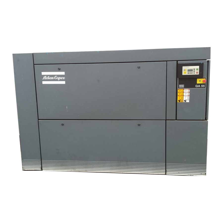
Atlas Copco GA55 User Manual
Stationary air compressors
Hide thumbs
Also See for GA55:
- Instruction book (44 pages) ,
- User manual (45 pages) ,
- Instruction book (212 pages)
Table of Contents
Advertisement
6060560
┌─Item Text
│ COMPRESSOR 460/60/3 116 CFM 150 PSI
│
│ Manufacturer: ATLAS COPCO
│ Mfr Part No : GA22FF
│ Size
│ Add'l Info
│
│
│
│
│
│
│ EACH COMPRESSOR INCLUDES: FOOD GRADE LUBRICANT (GA-FG)
│ AND GENERAL ALARM CONTACTS
└──────────────────────────────────────────────────────────────────────────────────┘
│COMPRESSOR 460/60/3 116CFM
──────────────────────────────────────────────────────────────────┐
: 116 CFM @ 150 PSI
: ROTARY SCREW, SINGLE STAGE, OIL INJECTED,
AIR COOLED, FULL FEATURE UNIT
WITH INTEGRATED REFRIGERATED DRYER,
COMPRESSOR FAILURE DRY CONTACTS.
30 HP,
460V, 3 PHASE, 60 HZ
40 IN LONG X 31 IN WIDE X 71 IN HIGH 1318 LBS.
│Cu
│
│
│
│
│
│
│
│
│
│
│
│
│
│
Advertisement
Table of Contents

Related Manuals for Atlas Copco GA55


Summary of Contents for Atlas Copco GA55
- Page 1 │COMPRESSOR 460/60/3 116CFM │Cu ┌─Item Text ──────────────────────────────────────────────────────────────────┐ │ COMPRESSOR 460/60/3 116 CFM 150 PSI │ │ │ │ Manufacturer: ATLAS COPCO │ │ Mfr Part No : GA22FF │ │ Size : 116 CFM @ 150 PSI │ │ Add'l Info : ROTARY SCREW, SINGLE STAGE, OIL INJECTED, │...
- Page 3 ® ® ® ® ® Important 1. This Manual applies exclusively to the compressors equipped with the Atlas Copco Elektronikon regulator. 2. This Manual must be used together with the relevant Instruction books for the compressors. • Copyright 1999, Atlas Copco Airpower n.v., Antwerp, Belgium.
- Page 4 User manual Page Page 1 General description ......3 10.3 Calling up running hours and service level ..14 1.1 Controlling the compressor .
-
Page 5: Controlling The Compressor
If desired, the function can be activated. Consult Atlas Copco. level. When stopping the compressor manually, the regulator will... - Page 6 User manual Ref. Designation Function Automatic Indicates that the regulator is operation LED automatically controlling the compressor: the compressor is loaded, unloaded, stopped and restarted depending on the air consumption and the limitations programmed in the regulator. Voltage on LED Indicates that the voltage is switched on.
- Page 7 (6) with the same symbol dryer) and the status of the motor can be used to see the previous item. overload protection. On GA55 up to -90C also the actual pressure difference over the oil separator,...
- Page 8 User manual Fig. 4.1. General menu flow 2920 1207 05...
- Page 9 User manual Fig. 4.2. Menu flow for regulator of GA5/45 2920 1207 05...
- Page 10 User manual Fig. 4.3. Menu flow for regulator of GA55(W)/75(W)/90C 2920 1207 05...
-
Page 11: Main Display: Compressor Status
If the function keys or arrow keys (5, 6 and 7-Fig. 2.1) are not running and loading hours, on used for 4 minutes, the regulator will automatically return to the GA55 up to GA90C also the main display. pressure difference over the oil separator. -
Page 12: Shut-Down And Motor Overload
Indicates that a sensor is out of The display indicates the name of the submenu which can be order: On GA55 up to GA90C: selected (only one name is shown, use the scroll keys (6-Fig. - Temperature sensor at the outlet 2.1) to find the other names). - Page 13 See section 7.3 to reset the shut-down message. the compressor runs unloaded or loaded. This warning indicates that: On water-cooled GA55/75 compressors, the cooling water outlet temperature exceeds the programmed warning level. 1. LED (3-Fig. 2.1) is alight and the main display screen will On Full-feature compressors (compressors with change into a screen similar to the one in Fig.
- Page 14 <<shut-downs>>, <<protections>> and <<start The status of the fan motor overload protection failures>> <<Rset>> (reset) on water-cooled GA55/75 also the actual cooling water outlet 3. Switch off the voltage and remedy the trouble. After temperature remedying and when the shut-down condition has disappeared, switch on the voltage and press the key <<Rset>>...
- Page 15 The bottom line of the screen shows the available function keys, i.e. <<Menu>> to return to submenu and <<Mod>> to modify the value of the indicated timer; if this should be required, consult Atlas Copco. Fig. 8.5. Example of a measured data display 2920 1207 05...
- Page 16 User manual Running hours 2050 Serv 2000 Rtrn ** Rset To call up and reset service messages for following monitored components: oil, oil filter, oil separator and air filter. Fig. 10.2. Example of a service display The bottom line again shows the available function keys, i.e.: <<Rtrn>>...
-
Page 17: Automatic Restart After Voltage Failure
Fig. 12.1. Example of a modifying screen (regulation settings) On water-cooled GA55/75 compressors also: Warning level for the cooling water outlet temperature The example in Fig. 12.1 indicates: Delay time for signal (i.e. - Page 18 ↓ (6-Fig. 2.1) to show the programmed delay option, i.e. dewpoint, can be selected. See section 12.4.2. for the shut-down; see Fig. 12.7. On water-cooled GA55/75 compressors, a second option, i.e. cooling water outlet temperature, can be selected. See section ↑...
- Page 19 (Fig. 12.10) appears. 8. Modifying is carried out in a similar way as described in On GA55/90C FF, a screen similar to the one shown in steps 3 and 4 of section 12.4.1. 9. Use the key <<Menu>> and the key ↑ to return to the initial (Fig.
-
Page 20: Control Panel
Footnotes chapter 12 during start; see Fig. 12.15. 1) If required, the automatic restart function after voltage failure can be activated by Atlas Copco. The power recovery time (the ↑ Cool water out period within which the voltage must be restored to have an... -
Page 21: Tabulator Key
User manual programmed start/stop commands will not be executed (but remain in the memory of the regulator). To program up to 56 start/stop commands for the compressor. 1. Press the key <<List>> on the timer screen. A typical display is shown in Fig. 13.2. ↑... - Page 22 User manual indication and the start/stop indication. See Figs. 13.6 The regulator does not accept a new compressor start/stop and 13.7. command unless it is situated between the next and previous 5. Press the key <<Prog>> (program) to program the new start/stop command timewise.
- Page 23 On the bottom line the key <<Menu>> to return to the submenu Footnotes chapter 14 2. By using the scroll key ↓ (6-Fig. 2.1) following data are 1) To be activated by Atlas Copco only 2920 1207 05...
-
Page 24: Main Display
By using the scroll key ↓ (6-Fig. 2.1), other data related to the <<Remote control>> means that these functions are shut-down can be called up. controlled remotely. Consult Atlas Copco. Line 3 indicates whether the timer which generates time- based start and stop commands is activated or not. See section 13. - Page 25 User manual To load and unload the compressor manually. Normally, the compressor is running in automatic operation, i.e. the electronic regulator loads, unloads, stops and restarts the compressor automatically. LED (1-Fig. 2.1) is then alight. If required, the compressor can be unloaded manually. In this case, the compressor is switched out of automatic operation, i.e.
- Page 26 Compressor element outlet temperature 4) ..... celsius (shut-down level) Delay at shut-down signal for GA55/90C 11) ....sec For Full-feature also 13): Dewpoint warning temperature for GA55/90C .
-
Page 27: Function
Oil separator (pressure difference) for GA55 up to -90C ..bar Oil separator (delay at signal) for GA55 up to -90C 6) ..sec... - Page 28 User manual Notes: Notes: Notes: Notes: Notes: ........................................................................................................................................................................................................................................................................................................................................................................................................................................................................................................................................................................................................................................................................................................................................................................................................................................................................................................................................................................................................................................................................................................................................................................................................................................................................................................................................................................2920 1207 05...
- Page 29 User manual Notes: Notes: Notes: Notes: Notes: ........................................................................................................................................................................................................................................................................................................................................................................................................................................................................................................................................................................................................................................................................................................................................................................................................................................................................................................................................................................................................................................................................................................................................................................................................................................................................................................................................................................2920 1207 05...
- Page 30 Instruction book Notes: Notes: Notes: Notes: Notes: ........................................................................................................................................................................................................................................................................................................................................................................................................................................................................................................................................................................................................................................................................................................................................................................................................................................................................................................................................................................................................................................................................................................................................................................................................................................................................................................................................................................2920 1207 05...
Need help?
Do you have a question about the GA55 and is the answer not in the manual?
Questions and answers
how to turn off the red light after filter change
To turn off the red light on the Atlas Copco GA55 after a filter change, follow these steps:
> (reset) key to reset the system.
1. Switch off the voltage and address any issues if needed.
2. Press the <
3. Press < to return to the main display.
4. Restart the compressor by pressing the start button (I).
This will reset any warnings or alarms, including the red light.
This answer is automatically generated
COMPRESSOR INDICATE NOT READY
what are the specs for the motor?
The specifications for the Atlas Copco GA55 motor are:
- Power Output: 55 kW (75 hp)
- Free Air Delivery (FAD): Approximately 8.1 m³/min (285 cfm) at 8 bar (116 psi)
- Pressure Range: Adjustable from 6 to 13 bar (87 to 188 psi)
- Noise Level: Approximately 68 dB(A) at 1 meter
- Weight: Approximately 600 kg (1323 lbs)
- Dimensions:
- Length: 1,700 mm (67 in)
- Width: 1,200 mm (47 in)
- Height: 1,300 mm (51 in)
- Motor Type: Oil-lubricated, no re-greasing required, IP66 certified, pressure-tight
- Drive: Vertical design direct drive, oil-cooled, no gears, belts, or shaft seal
This answer is automatically generated