Table of Contents
Advertisement
Instruction book
Atlas Copco Stationary Air Compressors
LE2, -3, -5, -7, -10, -15, -20
LT2, -3, -5, -7, -10 (50 Hz)
LT15/60, -15-30, -15, -20, -20-30
LF2, -3, -5, -7, -10
Instruction book
Copyright 2004, Atlas Copco Airpower n.v., Antwerp, Belgium.
Any unauthorized use or copying of the contents or any part thereof is prohibited.
particular to trademarks, model denominations, part numbers and drawings.
This instruction book meets the requirements for instructions specified by the machinery directive
98/37/EC and is valid for CE as well as non-CE labelled machines.
No. 2920 1585 00
Registration code: APC L / 38 / 985
2004-07
2920 1585 00
- 1 -
This applies in
Advertisement
Table of Contents

Subscribe to Our Youtube Channel
Related Manuals for Atlas Copco LE2


Summary of Contents for Atlas Copco LE2
- Page 1 Instruction book Atlas Copco Stationary Air Compressors LE2, -3, -5, -7, -10, -15, -20 LT2, -3, -5, -7, -10 (50 Hz) LT15/60, -15-30, -15, -20, -20-30 LF2, -3, -5, -7, -10 Instruction book Copyright 2004, Atlas Copco Airpower n.v., Antwerp, Belgium.
- Page 2 Follow all relevant safety precautions, including those mentioned on the cover of this book. Repairs must be carried out by trained personnel from Atlas Copco who can be contacted for any further information. In all correspondence mention the type and the serial number, shown on the data plate.
-
Page 3: Table Of Contents
Instruction book 1 Leading particulars ..........................5 1.1 General description..........................5 1.1.1 Compressor variants ........................8 1.2 Air flow ..............................9 1.2.1 LE/LF2 up to -5, LE7 and LE10 50 Hz (Fig. 1.10)................. 9 1.2.2 LE10 60 Hz, LE15, -20, LF7, -10 and LT (Fig. 1.11)..............9 1.3 Regulating system .......................... - Page 4 Instruction book 7.5.2 60 Hz ............................67 7.6 Compressor data for LT 20 bar......................68 7.6.1 50 Hz ............................68 7.6.2 60 Hz ............................68 7.7 Compressor data for LT 30 bar......................69 7.7.1 50 Hz ............................69 7.7.2 60 Hz ............................69 8 Conversion list of SI units into US/British units .................
-
Page 5: Leading Particulars
LE, LF and LT are air-cooled, single-acting piston compressors. LE and LT are lubricated compressors; LF are oil-less compressors which deliver oil-free air. LF2 up to LF5, LE2 up to LE7 and LE10 50 Hz are single-stage compressors; LE10 60 Hz, LE15, -20, LF7, -10 and LT are two-stage compressors. - Page 6 Instruction book Air filter Oil drain plug Motor Oil level sight-glass Cover Intercooler Air inlet silencer Crankcase Cooling pipe Cylinder Unloader Relief valve HP cylinder LP cylinder Fig. 1.3 Power Pack Figs. 1.1 up to 1.3 General views, Compressor Block - Power Pack Fig.1.5 Tank-mounted unit, LE10 60 Hz, LE5-20, LT15, Fig.
- Page 7 Instruction book D0656 Fig. 1.6 Tank-mounted unit, LE/LT/LF2, -3, -5, vertical Fig. 1.7 Tank-mounted unit, three-cylinder receiver (standard receiver is 250 l) 2920 1585 00 - 7 -...
-
Page 8: Compressor Variants
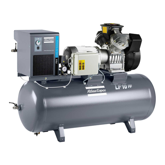
Instruction book Fig. 1.8 Base-mounted Fig. 1.9 LE/LF/LT with CD dryer Air cooler Blow-off silencer Air filter Air inlet silencer Air receiver Dewpoint indicator Air outlet valve Cooling pipe Check valve Electric cabinet Condensate drain valve Unloader Filler cap Relief valve Pictograph, switch off voltage and Air pressure gauge depressurize before maintenance or repair... -
Page 9: Air Flow
Instruction book For LE/LF/LT5 up to -10, LT15 up to -20: the Compressor Block as described above, with flanged-on electric motor (M) and solenoid valve (Y1-Fig. 1.5). The Tank-mounted unit comprises: For LE/LF/LT2 and -3: the Power Pack mounted on a horizontal (Fig. 1.4) or vertical (Fig. 1.6) air receiver (AR) with air outlet valve (AV), pressure gauge (Gp), safety valve (SV), air pressure switch with on/off switches (13) and condensate drain valve (Dm). - Page 10 Instruction book COMPRESSED AIR (1) Gp SV 50980D Compressed air Fig. 1.10 Air flow of LE and regulating system of LE/LF/LT2 up to -7 with DOL starter and separate air pressure switch COMPRESSED AIR (1) 50981D Compressed air Fig. 1.11 Air flow of LT and regulating system of LE5 up to -20, LF5 up to -10, LT5 up to -10 and LT15 up to -20 with Y/D starter and electric cabinet 2920 1585 00...
- Page 11 Instruction book COMPRESSED AIR D0338_1 Compressed air Fig. 1.12 Air flow of LE Trolley and regulating system of LE/LF/LT Trolley Air filter UV Unloading valve Air receiver Y1 Loading solenoid valve Air outlet valve Air inlet silencer AV1/2 Air outlet valves Pressure release valve Check valve Cylinder...
-
Page 12: Regulating System
Instruction book 1.3 Regulating system 1.3.1 LE/LF/LT2 up to -7 with DOL starter (Fig. 1.10) The regulating system includes: Check valve (CV) Air pressure switch (MDR) with pressure release valve (2) and on/off switches (5). Operation Air pressure switch (MDR) opens and closes its contacts at pre-set pressures. During loaded operation, the contacts are closed: the motor is running. -
Page 13: Le/Lf/Lt Trolley (Fig. 1.12)
Instruction book Fig. 1.13 Optional silencing hood Fig. 1.14 Pack compressor with optional silencing hood Air outlet valve Condensate drain valve Silencing hood (standard option) Electric cabinet On/off switch Air pressure switch with on/off switches Figs. 1.13 and 1.14 Pack - silencing hood 1.3.3 LE/LF/LT Trolley (Fig. - Page 14 Instruction book Fig. 1.15 LE/LF/LT ETROL Fig. 1.16 LE/LF/LT PETROL Air filter Unloader Air outlet valve Lifting yoke Condensate drain valve Cylinder Air pressure gauge Towing handle Electric motor Blow-off silencer Petrol engine Cover Pulsation damper Air inlet silencer Pilot valve Fuel tank Figs.
-
Page 15: Installation And Handling
Instruction book 2 Installation and handling 2.1 Dimension drawings (14) (14) 9820 2239 01/3 55749D See page 35 for the text on this figure Fig. 2.1 Dimension drawing, LE/LT2 up to -5 and LF2, -3 Power Pack 2920 1585 00 - 15 -... - Page 16 Instruction book (14) 9820 2239 02/3 55750D See page 35 for the text on this figure Fig. 2.2 Dimension drawing, LE/LT7, -10 and LF5, -7 Power Pack 2920 1585 00 - 16 -...
- Page 17 Instruction book 15-20 9820 2239 03/2 55751D See page 35 for the text on this figure Fig. 2.3 Dimension drawing, LE10 60 Hz, LE15, -20 and LF10 Power Pack 2920 1585 00 - 17 -...
- Page 18 Instruction book (14) 9821 0468 00/8 15-30 55755D 20-30 See page 35 for the text on this figure Fig. 2.4 Dimension drawing, LT15, -20 and LT15-30, LT20-30 Power Pack 2920 1585 00 - 18 -...
- Page 19 Instruction book (14) (15) Base- mounted 9820 2239 42/1 55752D See page 35 for the text on this figure Fig. 2.5 Dimension drawing, LE/LT2 up to -5 and LF2 Base-mounted 2920 1585 00 - 19 -...
- Page 20 Instruction book (14) (15) Base -mounted 9820 2239 43/1 55753D See page 35 for the text on this figure Fig. 2.6 Dimension drawing, LE/LT7 up to -10 and LF5, -7 Base-mounted 2920 1585 00 - 20 -...
- Page 21 Instruction book 15 - 20 (19) 9820 2239 44 55754D See page 35 for the text on this figure Fig. 2.7 Dimension drawing, LE10 60 Hz, LE15, -20 and LF10 Base-mounted 2920 1585 00 - 21 -...
- Page 22 Instruction book (15) 9820 8011 00/2 55756D See page 35 for the text on this figure Fig. 2.8 Dimension drawing, LT15, -20 Base-mounted 2920 1585 00 - 22 -...
- Page 23 Instruction book (10) (13) (12) 9820 2239 41/4 55757D See page 35 for the text on this figure Fig. 2.9 Dimension drawing, LE/LF/LT2 up to -7 and LE/LT10 50 Hz Pack with optional silencing hood 2920 1585 00 - 23 -...
- Page 24 Instruction book 15-20 (10) (13) (12) 9820 2239 40/3 55758D See page 35 for the text on this figure Fig. 2.10 Dimension drawing, LE10 60 Hz, LE15, -20 and LF10 Pack with optional silencing hood 2920 1585 00 - 24 -...
- Page 25 Instruction book (14) 9820 2239 21/3 55759D See page 35 for the text on this figure Fig. 2.11 Dimension drawing, Tank-mounted LE/LT2 up to -5 and LF2, -3 (horizontal 120 l receiver) 2920 1585 00 - 25 -...
- Page 26 Instruction book (14) 9820 2239 23/2 55760D See page 35 for the text on this figure Fig. 2.12 Dimension drawing, Tank-mounted LE/LT2 up to -5 (vertical 250 l receiver) 2920 1585 00 - 26 -...
- Page 27 Instruction book (14) 9820 2239 22/2 55764D See page 35 for the text on this figure Fig. 2.13 Dimension drawing, Tank-mounted LE/LT5 (horizontal 250/475 l receiver) 2920 1585 00 - 27 -...
- Page 28 Instruction book 15-20 9820 2239 27/5 55765D See page 35 for the text on this figure Fig. 2.14 Dimension drawing, Tank-mounted LE10 up to -20 and LF10 (horizontal 250/475 l receiver) 2920 1585 00 - 28 -...
- Page 29 Instruction book (14) (16) (17) (18) 15/60 15/60 9821 1041 00/8 52784D See page 35 for the text on this figure Fig. 2.15 Dimension drawing, Tank-mounted LT15, -20 (horizontal 250/475 l receiver) 2920 1585 00 - 29 -...
- Page 30 Instruction book 9820 2239 24/5 55767D See page 35 for the text on this figure Fig. 2.16 Dimension drawing, LE/LT2 up to -5 and LF2, -3 Tank-mounted with optional silencing hood 2920 1585 00 - 30 -...
- Page 31 Instruction book 9820 2239 26/5 55768D See page 35 for the text on this figure Fig. 2.17 Dimension drawing, LE/LT7, -10 and LF5, -7 Tank-mounted with optional silencing hood 2920 1585 00 - 31 -...
- Page 32 Instruction book 5-20 (14) (14) 7-10 7-10 15-20 9820 8006 00/3 55769D See page 35 for the text on this figure Fig. 2.18 Dimension drawing, LE/LT/LF with CD dryer 2920 1585 00 - 32 -...
- Page 33 Instruction book 2-10 (12) (11) (14) 9820 2239 71/3 55770D See page 35 for the text on this figure Fig. 2.19 Dimension drawing, LE/LF/LT Trolley with electrical motor 2920 1585 00 - 33 -...
- Page 34 Instruction book (14) 9820 2239 91 55771D See page 35 for the text on this figure Fig. 2.20 Dimension drawing, LE/LF/LT Trolley with petrol engine 2920 1585 00 - 34 -...
- Page 35 Instruction book Texts on figures 2.1 up to 2.20 Air inlet Hole, 15 x 25 (4x) Cooling air inlet Net mass Compressed air outlet, G 1/2 Manual condensate drain Hole, 15 x 25 (3x) Receiver Cooling air outlet (10) Motor cooling air inlet (11) Compressed air outlet (12)
-
Page 36: Installation Proposals
Instruction book 2.2 Installation proposals 9820 2332 03 52790D 9820 2332 00 52791D Fig. 2.21 Installation proposal for Tank-mounted unit Fig. 2.22 Installation proposal for Tank-mounted unit (120 l receiver) (250/475 l receiver) 2920 1585 00 - 36 -... - Page 37 Instruction book 9820 2332 04 52792D 9820 2332 02 52794D Fig. 2.23 Installation proposal for Tank-mounted Fig. 2.24 Installation proposal for Tank-mounted unit (vertical 250 l receiver) unit with optional silencing hood Cooling air outlet Compressor air and cooling air inlet 2920 1585 00 - 37 -...
-
Page 38: Le/Lf/Lt
Instruction book 9820 2332 01 52793D Cooling air outlet Compressor air and cooling air inlet Fig. 2.25 Installation proposal for Pack compressors 2.2.1 LE/LF/LT Install the compressor horizontally, in a cool but frost-free and well-ventilated room. Place the compressor as level as possible; however, LE/LT can be operated with an angular deviation below 22.5 degrees in any direction, LF can operate with any angular deviation, in any direction. -
Page 39: Le/Lf/Lt Trolley
Instruction book 2.2.2 LE/LF/LT Trolley The compressors are equipped with a lifting eye or yoke (1-Figs. 1.15 and 1.16). When running, the compressor must be installed as level as possible; however, it can be operated temporarily in an out-of-level position not exceeding 15 degrees. Keep the compressor in a frost- free and well-ventilated place. - Page 40 Instruction book 9820 2220 01 9820 2220 02 50924D 50925D Fig. 2.27 Electrical diagram of single-phase Fig. 2.28 Electrical diagram of 3-phase LE/LF/LT2 LE/LF/LT with direct-on-line starter up to -7 with direct-on-line starter 9820 8059 00/4 52787D Fig. 2.29 Electrical diagram of 3-phase LE/LT5 up to -10, LE15, -20, LF5 up to -10 and LT15/60, LT15, -20 with star-delta starter 2920 1585 00 - 40 -...
- Page 41 Instruction book This connection should be delivered in cubicle by the supplier 9820 8067 00/2 52788D This connection should be provided in cubicle by supplier Fig. 2.30 Electrical diagram of 3-phase LE/LT5 up to -10, LE15, -20, LF5 up to -10 and LT15/60, LT15, -20 with transformer and star-delta starter 2920 1585 00 - 41 -...
- Page 42 Instruction book FOR 230V A (CUBICLE COMPRESSOR) CONNECT F2 TO BE ADDED variant: MECHANICAL TIMER ELECTRONIC TIMER CD 2-3-6 CUBICLE COMPRESSOR variant: ELECTRONIC TIMER CD 7 ELECTRONIC 52789D TIMER Variant Mechanical timer Electronic timer Fig. 2.31 Electrical diagram of 3-phase LE/LT5 up to -10, LE15, -20 and LF5 up to -10 with star-delta starter and CD dryer F1/3 Fuses...
-
Page 43: Settings Of Overload Relay - Fuses - Cable Size
Instruction book 2.4 Settings of overload relay - fuses - cable size 2.4.1 Settings of overload relay - fuses of compressors with DOL starter 50 Hz Type Voltage Overload relay Fuses LE/LF/LT2 230 (1-phase) LE/LF/LT2 LE/LF/LT2 LE/LF2 LE/LF/LT3 230 (1-phase) 13.7 LE/LF/LT3 LE/LF/LT3... -
Page 44: Settings Of Overload Relay - Fuses Of Compressors With Y-D Starter
Instruction book 2.4.2 Settings of overload relay - fuses of compressors with Y-D starter 50 Hz Type Voltage Overload relay Fuses LE/LT5 LE/LT5 LE/LT5 LE/LF/LT7 12.2 LE/LF/LT7 LE/LF/LT10 14.5 LE/LF/LT10 LF10 LE15 21.5 LE15 13.1 LE15 LE20 29.4 LE20 16.9 LE20 13.7 Type... -
Page 45: Cable Size
Instruction book 60 Hz Type Voltage Overload relay Fuses 11.8 LE/LT5 LE/LT5 14.4 LF/LT7 LE/LT10 10.5 LE/LF/LT10 LE15 20.1 LE15 12.7 LE20 27.2 LE20 16.7 LE20 17.6 LE20 17.0 Type Voltage Overload relay Fuses LT15-30 LT15-30 15.7 LT15 LT15 15.7 LT20 18.1 LT20-30... -
Page 46: Pictographs
Instruction book 2.5 Pictographs Temperature Pressure Warning: voltage Switch off voltage and depressurize before maintenance or repair Read Instruction book before starting Consult Instruction book for correct direction of rotation Do not adjust switch if it is depressurized Fig. 2.32 Pictographs (typical examples) 2920 1585 00 - 46 -... -
Page 47: Operating Instructions
It is strongly recommended to install an interstage drain kit, to remove excess condensate, on LT compressors with a load factor less than 20% per hour. Consult Atlas Copco. 1. For Tank-mounted units, remove the transport brackets from underneath the compressor. -
Page 48: Stopping
Instruction book 6. Open the outlet valves (AV1/2-Figs. 1.12 and 1.16). 7. Set pilot valve (RV-Fig. 1.16) in the load position by turning the red handle 90 degrees (see section 5.6). 8. Turn the regulating knob of the pressure regulator (14-Fig. 1.12) clockwise or anti-clockwise to increase or decrease the pressure at the outlet of the pressure regulator. -
Page 49: Taking Out Of Operation At End Of Compressor Service Life
Instruction book 3.4 Taking out of operation at end of compressor service life At the end of the service life of the compressor, proceed as follows: 1. Stop the compressor and close the air outlet valve(s). 2. Switch off the voltage and disconnect the compressor from the mains. 3. -
Page 50: Maintenance
" 2000 Change blow-off silencer, if provided " 2000 On LE/LT, if mineral oil is used, change 2-yearly 3000 On LE/LT, if Atlas Copco PAO oil is used, change oil 4.4/5.1 Replace check valve or unloader ----- 3000 4000 4.4/5.2... -
Page 51: Lubrication Of Le/Lt Compressors
Instruction book 4.3 Lubrication of LE/LT compressors It is strongly recommended to use the Atlas Copco approved PAO (polyalphaolefine) compressor oil to keep the compressor in excellent operating condition. Atlas Copco PAO oil can be ordered in following quantities: PAO oil... - Page 52 Instruction book Service kit for valve discs Ordering number Ref. on Fig. 4.1 For LE2 up to -5 and LF2, -3 1503 5800 60 For LE7, LE10 50 Hz and LF5, LF7 1503 5800 61 For LT2 up to -5...
-
Page 53: Servicing And Adjustment Procedures
Dirt, condensate, coke formation and oxidation influence the proper operation of the valve. Depending on the environmental and working conditions (ambient temperature, working pressure, load cycle, oil type), the local Sales company may overrule the maintenance schedule (consult Atlas Copco). 5.2 Valves A faulty valve must be replaced immediately. - Page 54 Instruction book 52826D Fig. 5.3 High-pressure side of LE10 60 Hz, LE15, -20, LF10, LT20, LT20-30 Bolt Guide pin Joint 10 Joint O-ring 11 Cylinder Spring 12 Cylinder cover Outlet valve guard 13 Cylinder head Outlet valve disc 14 Joint Valve seat 15 Outlet cap Inlet valve disc...
-
Page 55: Replacement Of Valve Discs (Figs. 5.1 And 5.2)
Instruction book 5.2.1 Replacement of valve discs (Figs. 5.1 and 5.2) LE2, -3, -5, -7 HP cylinder HP cylinder Operation sequence LE10 50 Hz LF2, -3, -5 LE10 60 Hz LT15/60, -15 LE15, -20 LP cylinder for LT15-30 LF10 LE10 60 Hz... -
Page 56: Air Filter
Instruction book Torque value Torque value Torque value 10 Nm +/- 2 23 Nm +/- 2 M10: 46 Nm +/- 5 5.3 Air filter 1. Stop the compressor. 2. On LE/LF/LT2 up to -7, LE/LT10 50 Hz, LT15, -20 and LT15-30, LT20-30: unscrew the cap on top of cover (1-Fig. -
Page 57: Adjustment Of Mdr4S Pressure Switch (Figs. 5.4 Up To 5.6)
Instruction book 5.4 Adjustment of MDR4S pressure switch (Figs. 5.4 up to 5.6) The adjustment of the maximum or stopping pressure of the compressor is effected by means of the air pressure switch. The switch also controls the pressure difference between the maximum pressure (stopping pressure) and that at which compression is resumed (starting pressure). - Page 58 Instruction book Example: LE Stopping pressure: 7 bar(e) Starting pressure: adjustable between 3 and 5.7 bar(e) Fig. 5.6 Pressure difference diagrams, MDR4S/11 bar and MDR4S/25 bar 2920 1585 00 - 58 -...
-
Page 59: Adjustment Of Mdr3 Pressure Switch (Figs. 5.7 And 5.8)
Instruction book 5.5 Adjustment of MDR3 pressure switch (Figs. 5.7 and 5.8) The switch allows the operator to select the stopping pressure and the pressure difference between stopping and starting pressures. The stopping and starting pressures are the opening and closing pressures of the switch. -
Page 60: Adjustment Of Pilot Valve On Trolley (Fig. 5.9)
Instruction book 5.6 Adjustment of pilot valve on Trolley (Fig. 5.9) The adjustment of the maximum or unloading pressure of the compressor is effected by means of pilot valve (RV-Fig. 1.16). The valve also controls the difference between the preset maximum pressure and that at which compression is resumed. -
Page 61: Safety Valve (Sv-Figs. 1.4, 1.6 And 1.8) 1)
Instruction book 5.7 Safety valve (SV-Figs. 1.4, 1.6 and 1.8) 1) Replace the valve if it does not open at the correct pressure. No adjustments are allowed. Testing Testing as described below shall only be carried out by competent personnel. 5.7.1 Testing on LE/LF/LT 1. -
Page 62: Problem Solving
Instruction book 6 Problem solving Insufficient air pressure Air leak Check and correct as necessary Air filter choked Replace filter Air pressure switch incorrectly set Adjust switch Air consumption exceeds maximum output of compressor Check equipment connected Damaged valve Inspect valves and replace parts where necessary Unloader 1) malfunctioning Inspect and replace parts where necessary Solenoid valve 1) out of order... - Page 63 See 2d Ambient temperature too high Improve ventilation of room Motor stops and starts too frequently See 6 Overcurrent due to motor or compressor failure Consult Atlas Copco Footnote chapter 6 1) If provided. 2920 1585 00 - 63 -...
-
Page 64: Principal Data
Instruction book 7 Principal data 7.1 Reference conditions Inlet pressure (absolute) Relative air humidity Air inlet temperature °C Working pressure: - for LE 10 bar bar(e) - for LF 10 bar bar(e) - for LT 15 bar bar(e) - for LT 20 bar bar(e) - for LT 30 bar bar(e) -
Page 65: 60 Hz
Instruction book 7.3.2 60 Hz Compressor type LE10 LE15 LE20 Maximum working pressure for LE bar(e) Maximum working pressure for LE bar(e) Trolley Pre-set pressure difference for LE Trolley Temperature at outlet valve, approx. - Unsilenced compressor °C - Silenced compressor °C Power input at max. -
Page 66: Compressor Data For Lf 10 Bar
Instruction book 7.4 Compressor data for LF 10 bar 7.4.1 50 Hz Compressor type Maximum working pressure for LF bar(e) Maximum working pressure for LF bar(e) Trolley Pre-set pressure difference for LF Trolley Temperature at outlet valve, approx. - Unsilenced compressor °C - Silenced compressor °C... -
Page 67: Compressor Data For Lt 15 Bar
Instruction book 7.5 Compressor data for LT 15 bar 7.5.1 50 Hz Compressor type LT10 Maximum working pressure for LT bar(e) Maximum working pressure for LT bar(e) 13.7 13.7 13.7 13.7 13.7 Trolley Pre-set pressure difference for LT Trolley Temperature at outlet valve, °C approx. -
Page 68: Compressor Data For Lt 20 Bar
Instruction book 7.6 Compressor data for LT 20 bar 7.6.1 50 Hz Compressor type LT10 LT15/60 LT15 LT20 Maximum working pressure bar(e) Temperature at outlet valve, approx. - Unsilenced compressor °C - Silenced compressor °C Power input at max. working 2.04 2.56 4.21... -
Page 69: Compressor Data For Lt 30 Bar
Instruction book 7.7 Compressor data for LT 30 bar 7.7.1 50 Hz Compressor type LT10 LT15-30 LT20-30 Maximum working pressure bar(e) Temperature at outlet valve, approx. - Unsilenced compressor °C - Silenced compressor °C Power input at max. working 2.83 4.73 6.11 7.89... -
Page 70: Conversion List Of Si Units Into Us/British Units
Instruction book 8 Conversion list of SI units into US/British units 1 bar = 14.504 psi 1 g = 0.035 oz 1 kg = 2.205 lb 1 km/h = 0.621 mile/h 1 kW = 1.341 hp (UK and US) 1 l = 0.264 US gal 1 l = 0.220 Imp gal (UK) 1 l = 0.035 cu.ft 1 m = 3.281 ft... - Page 71 Instruction book Notes: 2920 1585 00 - 71 -...
- Page 72 Instruction book Notes: 2920 1585 00 - 72 -...
- Page 73 Atlas Copco compressor instruction book: ....Atlas Copco air dryer instruction book: ......
- Page 74 .
Need help?
Do you have a question about the LE2 and is the answer not in the manual?
Questions and answers