
Related Manuals for Gatekeeper Y35 HD v3


Summary of Contents for Gatekeeper Y35 HD v3
- Page 1 Y35 HD v3 User Manual & Install Guide Document Ref. No. : DN3342 Document Ref. No. : DN3342 Version No. : 1.0.5 Version No. : 1.0.5 Document Date : February, 2022 Document Date : February 2022...
-
Page 2: Table Of Contents
INTRODUCTION ..........................7 Y35 HD 3 ........................7 ELCOME TO ....................7 MPORTANT AFETY AND ANDLING NFORMATION YOUR Y35 HD V3 AT A GLANCE ....................9 ................................... 9 AKE A ’ ................................ 11 NCLUDED .............................. 12 YSTEM PECIFICATIONS ................................. 14 RIVE GPS .................................... - Page 3 Y35 HD v3 User Manual & Install Guide 6.3.2 Time Setup ................................. 68 6.3.3 Startup ................................. 71 6.3.4 User Setup ................................74 6.3.5 Network ................................75 6.3.6 Application ................................. 80 6.3.7 Other Setup................................ 80 .............................. 81 URVEILLANCE ETTINGS 6.4.1 Live View ................................82 6.4.2...
- Page 4 TABLE OF FIGURES Figure 2-1 Front View of the Y35 HD v3 ..........................9 Figure 2-2 Close Up View of the Y35 HD v3 Status Indicator Lights ............... 9 Figure 2-3 Rear View of the Y35 HD v3 ..........................10 Figure 3-1 Side View of the Finger Mouse ........................
-
Page 5: Glossary
Y35 HD v3 User Manual & Install Guide GLOSSARY Term/Abbreviation Description Accelerometer Controller Area Network is a vehicle bus standard designed to allow microcontrollers and devices to communicate with each other in applications without a host computer. Digital Video Recorder – a device which records audio and video input from the cameras and stores it to a hard disk drive and/or an SD card for retrieval and viewing. - Page 6 Y35 HD v3 User Manual & Install Guide MAC Address Media Access Control address – it is a unique identifier assigned to network interfaces for communications on the physical network segment. On Screen Display – an image superimposed on a screen commonly used to display information such as volume, channel, date/time, device status, etc.
-
Page 7: Introduction
15% to 20% less data which means longer recording times. The Y35 HD v3 is a 5 channel, SSD based MDVR. The MDVR supports 4 Analog High Definition (AHD) channels and 1 IP channel. Each AHD and IP channel supports up to 1080p and up to 30 FPS with selectable resolutions and 8 quality levels. - Page 8 The hard drive is specially formatted for use in your Y35 HD v3. Please do not format it ▪...
-
Page 9: Your Y35 Hd V3 At A Glance
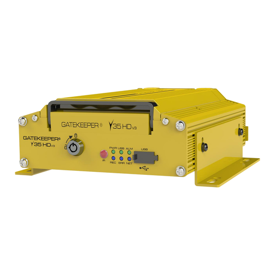
E. USB Port: external USB flash drives which can be used for saving/uploading configuration ▪ files, updating system firmware and downloading of recorded video/event files. Figure 2-2 Close Up View of the Y35 HD v3 Status Indicator Lights 9 of 156... -
Page 10: Figure 2-3 Rear View Of The Y35 Hd V3
Illuminated green indicates network connection is available. (Note: The LAN LED status light is currently not supported) This is the back panel of the Y35 HD v3 Figure 2-3 Rear View of the Y35 HD v3 A. GPS Antenna In: This is the connection point for the external GPS antenna. -
Page 11: Included
Power Cable (CAB000360) This is the vehicle power ignition cable for powering the Y35 HD v3 and its connected accessories. Sensor/Serial Cable (CAB000376) This is the sensor cable for connecting the various sensor input to the Y35 HD v3. -
Page 12: System Specifications
There are numerous customisable options and accessories which can tailor the product installation to fit your unique operating environment and requirements. Please contact Gatekeeper Systems for information on optional download kits and other accessories for use with your product. 2.3 System Specifications... - Page 13 Y35 HD v3 User Manual & Install Guide Audio Compression ADPCM, G.711A, G.711U Storage Hard Drive Support single CMR HDD or SSD up to 2TB Recording Recording Mode Boot up/Schedule/Alarm Recording Trigger Recording Trigger Schedule, alarms, sensor triggers Pre-recording Supported...
-
Page 14: Hard Disk Drive
2.4 Hard Disk Drive The Y35 HD v3 utilizes an SSD for the storage of video and has one caddy. Hard Drives are very simple to use and are very reliable. The Hard Drives supplied by Gatekeeper Systems have been extensively tested and are the only approved Hard Drives for use in the Y35 HD v3. -
Page 15: Getting Started
3.1 Learning How to Navigate Your Y35 HD v3 comes with a simple graphical user interface from which you can access all the features and functions. You can select from a choice of intuitive interface devices with which to navigate the system. Depending on your product package, your Y35 HD v3 will have come bundled with one of the following accessories for accessing the user interface. -
Page 16: Using The Ir Remote Control
Y35 HD v3 User Manual & Install Guide 3.1.1 Using the IR Remote Control The infra-red remote control, together with the accompanying LCD monitor, allows you to access the DVR functions and menu system. Front View of the IR Remote Control (Please Note: The remote you receive may appear slightly different to the one depicted here) Setup: To access the menu use the Setup button. - Page 17 Y35 HD v3 User Manual & Install Guide How to Connect the IR Remote Control and LCD Monitor Connecting the IR Remote Control and LCD Monitor 17 of 156...
-
Page 18: Using The Trackball Mouse
3.1.2 Using the Trackball Mouse. The trackball mouse, together with the accompanying LCD monitor, provides one way to access the Y35 HD v3 menu and functions using a familiar graphical user interface point-and-click system. Figure 3-1 Side View of the Finger Mouse Right Button: When viewing video streams, pressing this button will toggle between showing ▪... -
Page 19: Using The Interactive Control Display (Icd2)
Y35 HD v3 User Manual & Install Guide How to Connect the Finger Mouse and LCD Monitor Figure 3-2 Connecting the Finger Mouse and LCD Monitor 3.1.3 Using the Interactive Control Display (ICD2) The ICD2 is a full featured touch display that makes navigating the device menu system very intuitive. -
Page 20: Figure 3-3 Front View Of The Icd2
Y35 HD v3 User Manual & Install Guide Figure 3-3 Front View of the ICD2 Touch Screen: A single tap anywhere on the screen (when showing video ▪ streams) will bring up the on-screen quick menu. Another single tap anywhere on the screen will hide the quick menu again. At all times, tapping on an on-screen field, tab or button in the menu system will select it. -
Page 21: Guide To Common Navigation Actions
ICD2 connector cable (CAB000391) to CAB000390 and to the ICD2. Using the remote or mouse, log into the Y35 HD v3 and under: Setup -> Collection -> Serial Port -> RS232, set this connection to CP4 and ensure Baud is set to 57600, hit apply and then restart the unit. Note that you cannot connect a Driver Alert button and an ICD2 at the same time. - Page 22 Y35 HD v3 User Manual & Install Guide Action IR Remote Finger Mouse ICD2 Pressing an on- Move the cursor using Move the on-screen Tap the on-screen screen button. Arrow Keys until the pointer using the Track button with your finger.
- Page 23 Y35 HD v3 User Manual & Install Guide Action IR Remote Finger Mouse ICD2 Whilst still holding the Trigger Button, now simultaneously move the on-screen pointer using the Track Ball. This will drag the item in the direction which you are moving the pointer.
-
Page 24: The Y35 Hd V3 Start-Up Screen Layout
3.3 The Y35 HD v3 Start-up Screen Layout Upon start-up, the screen of the Y35 HD v3 will display the live video streams from the various cameras attached to the Y35 HD v3. Users can select and configure how many video channels to be displayed on the screen for monitoring purposes. -
Page 25: Figure 3-5 Y35 Hd V3 Startup Screen
Y35 HD v3 User Manual & Install Guide Figure 3-5 Y35 HD v3 Startup Screen Live Video From Cameras: By default, upon system start-up, the screen will display live video ▪ from the camera attached to channel one in single camera full onscreen view. Clicking anywhere... -
Page 26: Viewing Live Video
Y35 HD v3 User Manual & Install Guide 3.4 Viewing Live Video Single Camera On-screen View When the screen is in Single Camera On-screen View mode, camera from a single camera ▪ channel will be shown on the entire screen. -
Page 27: Figure 3-7 Example Of Video Loss
Y35 HD v3 User Manual & Install Guide camera. This will switch the display to Single Camera On-screen View to display the video from the selected camera. Alternatively, with the Finger Mouse or the ICD2, you could also click on any video stream on ▪... -
Page 28: Quick View Of System Status Information
▪ Device ID ▪ Serial Number ▪ MAC Address – This is the Lan MAC ▪ Address of the Y35 HD v3 Firmware Version ▪ MCU Version ▪ ICD Version – this is the ICD firmware ▪ 28 of 156... - Page 29 3. Module Status – GPS. This screen shows a summary of the GPS of the Y35 HD v3. Module status defines the physical • location of the Y35 HD v3 using GPS co- ordinates. Location source defines where the • Location is sourced.
-
Page 30: Logging Into The System
3.6 Logging into the System In order to access many of the Y35 HD v3 advanced functions, you will need to be logged in to the system. This is a security measure to ensure that access to sensitive functions and video data is restricted to authorised users. - Page 31 Y35 HD v3 User Manual & Install Guide Access to the following functions require the user to be logged in: Access from the on-screen quick menu: Playback ▪ Access to the Main Menu and the following functions: REC Search ▪...
- Page 32 If the password is correct, you will be logged-in and allowed to access the advanced ▪ functions of the Y35 HD v3 and the Main Menu. At any time, you may also cancel the log-in process by clicking the (Cancel) button.
-
Page 33: Understanding The Main Menu
Logout: Logout the current logged-in user. This will return the system to the live video view. ▪ The Record Search and Log Search functions will be explained in the chapter on Viewing Recorded Data, whilst the Setup function will be explained in the chapter on Configuring the Y35 HD v3. 33 of 156... -
Page 34: Basic System Quick Start
4.1 Step 1: Powering Up the Y35 HD v3 The Gatekeeper Project Team are able to mount and install the device into the vehicle based on your requirements and in accordance with industry best practices from years of experience. If you prefer to... -
Page 35: Step 3: Logging In And Accessing System Configuration
Y35 HD v3 User Manual & Install Guide 4.3 Step 3: Logging in and Accessing System Configuration You may now log into the system and go to the Main Menu where you can access the device Setup and configuration settings. - Page 36 ▪ Understanding the Setup Menu System for System Configuration The Y35 HD v3 comes with a comprehensive setup menu system where you will be able to tailor almost every aspect of the device operations to your unique fleet requirements. The configuration options in the menu are broken into 5 major sections: Basic Setup –...
-
Page 37: Step 4: Setting The Date And Time
Y35 HD v3 User Manual & Install Guide Alarm – where you will be able to configure recording, snapshot and other actions which the ▪ device will perform when an alarm event occurs. For a detailed explanation, please see Section 6.6. -
Page 38: Step 5: Setting The Vehicle Identity Information
Y35 HD v3 User Manual & Install Guide Time Sync Date/Time DEFAULT SETTINGS: Please verify the time and date. If the time and/or date is not correct, please change them to the correct values. Satellite DEFAULT SETTINGS: Checkbox – Selected ▪... -
Page 39: Step 6: Setting Basic Preferences
User Manual & Install Guide Device Info Device ID Leave this value as it is, unless directed to change by Gatekeeper Project Team. Vehicle Info Vehicle Plate You can use this field to key in the vehicle registration plate number. -
Page 40: Step 7: Setting Up Authorised Users
Main Menu Setup Basic Setup User Setup → → → The Y35 HD v3 comes pre-configured with the following two default user accounts: Default administrator user Username – admin ▪ Password - admin ▪ Default normal user Username – user ▪... - Page 41 User Manual & Install Guide It is highly recommended that you do not change the password on the default administrator account, as this account will be used by authorised Gatekeeper Systems engineers to troubleshoot your device during support and maintenance.
-
Page 42: Step 8: Setting Up Recording
User Manual & Install Guide 4.8 Step 8: Setting Up Recording The Y35 HD v3 is a hybrid DVR. It has the capability of having a combination of analog, analog HD, and a single IP camera connected at the same time. - Page 43 Y35 HD v3 User Manual & Install Guide connected. Please note that the system will show a video loss message on channels which are enabled, but do not have a connected camera (i.e., no incoming video stream). Likewise, for channel 5 (Digital IP Camera channel), only enable this channel if it actually has a camera connected.
-
Page 44: Step 9: Setting U Pip Cameras
Y35 HD v3 User Manual & Install Guide Enable DEFAULT SETTINGS: Checkbox - Selected ▪ Encode Standard DEFAULT SETTINGS: H264 ▪ Audio DEFAULT SETTINGS: Always Audio ▪ Resolution DEFAULT SETTINGS: ▪ Frame Rate DEFAULT SETTINGS: ▪ Quality DEFAULT SETTINGS: ▪... -
Page 45: Step 10: Finish
Section 6.4.3 to setup the IP Camera in your system. 4.10 Step 10: Finish Your new Y35 HD v3 system is now setup and ready to go! Please also review Chapter 5 to learn about viewing and clipping the recorded video. -
Page 46: Viewing Recorded Data
Y35 HD v3 User Manual & Install Guide 5 Viewing Recorded Data 5.1 Using the Playback Feature The Playback feature can be accessed from the on-screen quick menu after logging in. It functions as a shortcut which allows the user to immediately access and view recorded video from the start of the current day (beginning 00:00:00H) till the current time of the day. -
Page 47: Figure 5-2 Playback On-Screen Controls
Y35 HD v3 User Manual & Install Guide The Video Playback On-Screen Controls If you are using a Finger Mouse, you can toggle the on-screen controls by pressing the Right Button, whereas with the ICD2, you would just tap anywhere on the video. If there is no user input, then the on- screen playback controls will auto-hide after 15 seconds of inactivity. - Page 48 Y35 HD v3 User Manual & Install Guide Current Playback Time Control: This shows the current playback time. Selecting it will bring up ▪ the time control dialog which allows you to key in a specific time (in hh:mm:ss 24-hour time format) from which to begin the playback.
-
Page 49: Using Rec Search
The REC Search feature can be accessed from the Main Menu after logging in. It allows the user to search for and view any recorded video which is stored on the Y35 HD v3 storage Hard Drive. Users can also select and export video clips of specific time periods to an external storage device (such as USB flash drive) for later viewing. -
Page 50: Figure 5-4 Rec Search Camera Channel Controls
REC Search Step 2: Selecting the Camera Channels In a complex multi-camera configuration such as the Y35 HD v3 which can have up to 5 connected cameras in total, even a single day may contain a lot of recorded video data. This next step allows you to filter the data by selecting only the camera channels of interest to view. -
Page 51: Figure 5-5 Rec Search Time Controls
Y35 HD v3 User Manual & Install Guide All available video. Normal : Normal video only (without any alarm events). Alarm Only videos with alarm events. Locked Only locked videos. Select Camera Channels: Click to toggle select the camera channels to include. Selected camera ▪... - Page 52 Y35 HD v3 User Manual & Install Guide Scroll Time Scale: After zooming in, the entire days’ time scale will not be able to fit on the ▪ screen display. Click the (<) and (>) buttons to scroll the time scale to the left and right respectively.
-
Page 53: Figure 5-6 Rec Search Playback Controls
Y35 HD v3 User Manual & Install Guide If more than 1 camera channel was selected during the previous step, all selected channels will be displayed in quad screen mode (2x2 grid layout). With a Finger Mouse or ICD2, you can easily select a single channel to view in full screen by double-clicking on it. - Page 54 Y35 HD v3 User Manual & Install Guide Cycle to Next Channel: Switch playback to the next camera channel. For example, if the system ▪ is currently playing recorded video from Camera 3, then clicking this button will switch to playing recorded video from Camera 4.
- Page 55 Please Note: If you are using the Finger Mouse/LCD combination to navigate you will need to use a Gatekeeper Systems USB Hub to allow two devices to share the one USB port.
- Page 56 Click the (Export) button to proceed. ▪ You may also click the (Cancel) button in order to go back and select a different ▪ time period. Gatekeeper Systems USB hub. Note the instructions for the correct order in which to connect devices. 56 of 156...
-
Page 57: Using Log Search
(such as USB flash drive) for later viewing. Please Note: If you are using the Finger Mouse/LCD combination to navigate you will need to use a Gatekeeper Systems USB Hub to allow two devices to share the one USB port. Log Search Step 1: Selecting the Date The first step in the Log Search screen allows you to select a date to view the associated log files. -
Page 58: Figure 5-7 Log Search Date Controls
Y35 HD v3 User Manual & Install Guide Figure 5-7 Log Search Date Controls Main Menu: Click this icon to return to the Main Menu. ▪ Back to Previous Screen: Click this icon to return to the Previous Screen that you were at. -
Page 59: Figure 5-8 Log Time And Type Selection
Y35 HD v3 User Manual & Install Guide Figure 5-8 Log Time and Type Selection Main Menu: Click this icon to return to the Main Menu. ▪ Back to Previous Screen: Click this icon to return to the Previous Screen that you were at. -
Page 60: Figure 5-9 View And Export Log File
Y35 HD v3 User Manual & Install Guide All: Show all alarm events. IO Alarm: Only show IO alarm events. Driver Alert: Only show panel alarm events. Speed Alarm: Only show speed alarm events. Video Loss: Only show Video Loss events. -
Page 61: Configuring The Y35 Hd V3
6 Configuring the Y35 HD v3 6.1 Quick Reference to Configuration Menu System The following shows a high-level map to the various settings in the Y35 HD v3 configuration menu system. Please refer to the following sections for a detailed description of each section. -
Page 62: Navigating The Configuration Menus
Y35 HD v3 User Manual & Install Guide 6.2 Navigating the Configuration Menus The configuration menus are presented in a tabular format, where the main sections can be selected from the row of tabs at the top of the screen. The subsections within each main section are arrayed in columnar format, and can be selected from the column of page subsections on the left edge of the screen. - Page 63 If you navigate away from the current page/tab without saving, any changes that you have made to the settings will be discarded. Please note that your configuration settings have been set by Gatekeeper Systems engineers to meet your specific deployment requirements. Do not reset to factory defaults or change the settings unless you fully understand the changes you are making, or as directed by Gatekeeper Systems.
- Page 64 Y35 HD v3 User Manual & Install Guide Text Field This is a general field which accepts user input. Clicking the field will display an on-screen full qwerty keyboard for the user to key in the text (both alphabetical and numbers).
-
Page 65: Basic Settings
Y35 HD v3 User Manual & Install Guide Drop List This is a controlled input field which only accepts selections from a predefined list of items. This kind of field can be identified by a (v) button to the right of the field. Clicking this button will display a list of items which can be scrolled and selected. -
Page 66: Regist Info
You may input up to a maximum of: 5 digits ▪ Note: This value is only set when the device is configured as part of a Gatekeeper Wireless deployment. DEFAULT SETTINGS: Please contact Gatekeeper Project Team, in consultation with customer/school district, for the value to set. - Page 67 Y35 HD v3 User Manual & Install Guide DEFAULT SETTINGS: Gatekeeper Project Team, in consultation with customer/school district will determine the value to set. Line Number Alphanumeric text field for setting the vehicle line number. Typically, the identification code used by the fleet operator to identify a route.
-
Page 68: Time Setup
Y35 HD v3 User Manual & Install Guide 6.3.2 Time Setup Navigate to: Main Menu Setup Basic Setup Time Setup → → → The device contains a real time clock. This subsection enables you to view and set the date and time for the device, and also configure the options used for time synchronization as well as daylight savings. - Page 69 GPS satellites. Note: This is the recommended setting to use when the Y35 HD v3 is deployed in a mobile environment. To use this setting, the Y35 HD v3 must be equipped with the GPS option.
- Page 70 Y35 HD v3 User Manual & Install Guide Note: This setting requires a constant network connection either via cellular or Wi-Fi. DEFAULT SETTINGS: Checkbox – Unselected ▪ Checkbox – selecting this will enable the device Enable to calculate and adjust for daylight savings time.
-
Page 71: Startup
Y35 HD v3 User Manual & Install Guide Time field to set the start time. ▪ DEFAULT SETTINGS: MAR (month) ▪ 2ND (week) ▪ SUNDAY (day) ▪ 02:00 (time) ▪ This is a set of fields which allow you to choose the ending point of the period for which the device will adjust for daylight savings time. - Page 72 Y35 HD v3 User Manual & Install Guide Ignition or Timer – device will start ▪ either when vehicle ignition is on, or when the scheduled time starts. However, the device will only turn off when BOTH ignition is off AND scheduled time ends.
- Page 73 Y35 HD v3 User Manual & Install Guide Notes: Currently, this is the only option available. DEFAULT SETTINGS: No Consumption Standby ▪ This means that the device will not be consuming battery power when it is shut down. DVR Voltage Setup Checkbox –...
-
Page 74: User Setup
Y35 HD v3 User Manual & Install Guide DEFAULT SETTINGS: Checkbox – Unselected ▪ 6.3.4 User Setup Navigate to: Main Menu Setup Basic Setup User Setup → → → This subsection enables you to add and edit users, as well as change the passwords required to log into the system. -
Page 75: Network
These include settings for the local network, web port settings, Wi-Fi, and center server settings. NOTE: THE FOLLOWING SECTION (SERVER) IS ONLY APPLICABLE WHEN THE DEVICE IS BEING CONFIGURED AS PART OF A GATEKEEPER WIRELESS DEPLOYMENT. Server Center Server... - Page 76 Y35 HD v3 User Manual & Install Guide currently set configuration values, and allow you to modify them. These configuration values are server specific. If you have more than one center server set up, you will need to select each in turn and configure them separately.
- Page 77 Y35 HD v3 User Manual & Install Guide Local ▪ Wi-Fi ▪ Auto Adaptation ▪ DEFAULT SETTINGS: Auto Adaptation ▪ Register Server IP Numeric text field to configure the IP address of the register server demo2.g4-enterprise.com Register Server Port Numeric text field to configure the port...
- Page 78 Y35 HD v3 User Manual & Install Guide DEFAULT SETTINGS: Checkbox – Selected ▪ IP Address Numeric text field allowing you to key in the IP address for the device. DEFAULT SETTINGS: 192.168.88.2 ▪ Subnet Mask Numeric text field allowing you to key in the IP address subnet mask for the device.
- Page 79 Y35 HD v3 User Manual & Install Guide Alternate Numeric text field allowing you to key in Server the IP address of the alternate DNS server. DEFAULT SETTINGS: 192.168.88.1 ▪ Ports WEB Port Numeric text field to set the web port number.
-
Page 80: Application
This subsection enables you to view and edit the application settings of the device in regards to Download. Please note this option is currently not supported and is reserved for future development. NOTE: GATEKEEPER DOES NOT SUPPORT THIS CONFIGURATION. FTP Server... -
Page 81: Surveillance Settings
Y35 HD v3 User Manual & Install Guide Preview Volume DEFAULT SETTINGS ▪ Algorithm ADAS Camera Install DEFAULT SETTINGS Height 153 cm ▪ AI Alarm Voice Enable: DEFAULT SETTINGS: Checkbox – Selected ▪ Calibration Name DEFAULT SETTINGS: ▪ Channel name... -
Page 82: Live View
Y35 HD v3 User Manual & Install Guide Figure 6-3 Surveillance Tab in the Device Configuration Options 6.4.1 Live View Navigate to: Main Menu Setup Surveillance Live View → → → This subsection enables you to configure the settings for the live view of the video coming from the cameras. - Page 83 Y35 HD v3 User Manual & Install Guide Image Setup Menu: The entire image setup menu is floating over the video from the live ▪ camera. You may click and drag the entire image setup menu up and down in order to look at different parts of the image.
- Page 84 Y35 HD v3 User Manual & Install Guide Revert to Defaults: Click the (Default) button to revert the settings to the factory defaults. ▪ Save Settings: Click the (Save) button to save the settings to the currently selected camera ▪...
- Page 85 Y35 HD v3 User Manual & Install Guide DEFAULT SETTINGS: Quad ▪ Channel Checkboxes – allows you to select the cameras to be included as part of the live view displayed channels. Notes: You are allowed to select more display channels than there are cameras available.
- Page 86 Y35 HD v3 User Manual & Install Guide Mode: This enables you to choose the display mode, whether channels will be displayed in ▪ single, double, quad, or 9-split mode. Single : Single camera (1x1) on the screen Double : Two cameras on the screen in 2x1 (double) grid layout...
- Page 87 Y35 HD v3 User Manual & Install Guide Auto Loop Checkbox – if selected will enable the auto-loop feature. DEFAULT SETTINGS: Checkbox – Unselected ▪ Live OSD Date/Time Checkbox – if selected, the date and time will be displayed as an overlay text on top of the live video view on the LCD monitor or ICD2.
-
Page 88: Record
→ → The Y35 HD v3 is a hybrid DVR. It has the capability of having a combination of analog; analog HD and a single IP camera connected at the same time. Please Note: The IP camera is a separate device and uses its own settings. Analog HD cameras have a maximum frame rate of 30 Frames Per Second. - Page 89 Y35 HD v3 User Manual & Install Guide specify the number of days to keep video retained before overwriting. By Capacity – video will be retained as ▪ long as storage capacity is available. As device storage capacity runs out, older...
- Page 90 Y35 HD v3 User Manual & Install Guide None ▪ DEFAULT SETTINGS: None ▪ Note: If the Sub-Record, Alarm Backup, or Mirror Record options are selected, then the SD Write Resource Ratio, Record Storage, and Channel parameters become available. Storage...
- Page 91 Y35 HD v3 User Manual & Install Guide Enable Checkbox – if selected, enables this channel for inclusion into the main stream recording. DEFAULT SETTINGS: For channels 1 to 5, only enable the ▪ channels which actually have cameras connected. Please note that the system...
- Page 92 Y35 HD v3 User Manual & Install Guide Quality Drop list allowing you to select the encoding quality (on a scale of 1 to 8 – where 1 is best). DEFAULT SETTINGS: For all channels (1 to 5), set the following: 1 (Best) ▪...
- Page 93 (jaggedness and blurriness) into the encoded video as the encoder attempts to keep up with quick changing video scenes continuously adjusting the bit rate. For optimal recorded video quality, Gatekeeper Systems recommends the use of the CBR setting throughout. DEFAULT SETTINGS: 93 of 156...
- Page 94 Y35 HD v3 User Manual & Install Guide For all channels (1 to 5), set the following: ▪ Audio Coding Format DEFAULT SETTINGS: ADPCM ▪ Copy To This feature allows you to easily copy the configuration settings on this channel to another selected channel.
- Page 95 Y35 HD v3 User Manual & Install Guide the identifier data which is set in the Basic Setup Regist Info Vehicle Info → → → Vehicle Plate. DEFAULT SETTINGS: Checkbox – Unselected ▪ Channel Name Checkbox – if selected, the channel name will be displayed as an overlay text on top of the recorded video.
- Page 96 Y35 HD v3 User Manual & Install Guide Text Data Overlay: The selected data is displayed as a text overlay on top of the video. ▪ Moving the Text Data: The position of the text data can be easily customised by moving it to ▪...
-
Page 97: Ipc Setup
Camera Channels: The available camera channels are listed on the screen along with their ▪ associated settings. Please Note: On a Y35 HD v3 there is only One IP camera channel, channel 5. Scroll Page: Use the (^) and (v) buttons to scroll the list of camera channels up and down ▪... -
Page 98: Figure 6-5 4 Ip Camera Settings Configuration Screen
The available IP camera will be displayed in a list together with the default settings for IP address, port and protocol type which have be automatically configured by the Y35 HD v3. Step 1 : Click on the checkbox to select the associated camera. -
Page 99: Collection Settings
Y35 HD v3 User Manual & Install Guide Revert to Defaults: Clicking the (Default) button will revert all the settings to their defaults. Save Settings: The (Save) button allows you to save the IP camera configuration settings. 6.5 Collection Settings... - Page 100 Y35 HD v3 User Manual & Install Guide currently set configuration values, and allow you to modify them. These configuration values are specific to each sensor (as identified by sensor number). You will need to select each sensor number in turn and configure them separately.
- Page 101 Y35 HD v3 User Manual & Install Guide Sensor Number: 5 Sensor Name – LEFTTURN ▪ OSD Name – LT ▪ Sensor Number: 6 Sensor Name – RIGHTTRN ▪ OSD Name – RT ▪ Sensor Number: 7 Sensor Name – EXTRA1 ▪...
- Page 102 If the measurement unit is set to Pulse, you will also need to select the calibration mode and perform a manual calibration. Pulse mode is currently unsupported, and Gatekeeper Systems recommends the use of Satellite for this setting. 102 of 156...
-
Page 103: Advanced
Y35 HD v3 User Manual & Install Guide DEFAULT SETTINGS: Satellite ▪ Location Navigation Mode DEFAULT SETTINGS: ▪ Mileage Total Displays the total mileage which the vehicle has travelled. Base Value Sets the mileage of the vehicle on first day of service on that route. -
Page 104: Snap Setting
Y35 HD v3 User Manual & Install Guide Type DEFAULT SETTINGS: None ▪ Note: Type will show different UI styles for each device if changed from default. Subtype DEFAULT SETTINGS: Disabled/not applicable ▪ IP Address DEFAULT SETTINGS: 192.168.001.100 ▪ Port... - Page 105 Snap Enable – if the checkbox is ▪ selected, then this camera channel is included when the Y35 HD v3 performs the snap shot task. Resolution – this drop list enables you ▪ to select the resolution for the snapshots.
- Page 106 Snap Enable – if the checkbox is ▪ selected, then this camera channel is included when the Y35 HD v3 performs the snap shots. Resolution – this drop list enables you ▪ to select the resolution for the snapshots.
-
Page 107: Eco-Driving
6.5.4 ECO-Driving. Navigate to: Main Menu Setup Collection ECO-Driving → → → This menu option is currently unsupported by Gatekeeper Systems and is reserved for future development. NOTE: GATEKEEPER DOES NOT SUPPORT THIS CONFIGURATION. RESERVED FOR FUTURE IMPLEMENTATION 107 of 156... -
Page 108: Maintenance
Y35 HD v3 User Manual & Install Guide ODBII Manufacturer Model DEFAULT SETTINGS: Unknown ▪ Engine Link State DEFAULT SETTINGS: Disconnect ▪ Current Software Version DEFAULT SETTINGS: Unknown ▪ Calibration Currently Unsupported. GDS Platelet Total Mileage Base DEFAULT SETTINGS: ▪... -
Page 109: Base
Y35 HD v3 User Manual & Install Guide Figure 6-7 Alarm Tab in the Device Configuration Options 6.5.6 Base Navigate to: Main Menu Setup Alarm Base → → → This subsection enables you to set up the trigger for alarm events based on IO input, speed, driver alert, and also to define the actions that will be taken when the alarm occurs. - Page 110 Y35 HD v3 User Manual & Install Guide Event ▪ Trigger Click the (Setup) button under Trigger to display the Trigger setup screen for the associated IO input line. This will display a drop list which allows you to select the trigger for this IO input line: Low (0V) ▪...
- Page 111 Y35 HD v3 User Manual & Install Guide Output Delay Time – numeric text ▪ field to set the delay time for the IO output (in seconds). Alarm Image Upload – checkbox, if ▪ selected will enable the device to upload the alarm to the center server.
- Page 112 Y35 HD v3 User Manual & Install Guide DEFAULT SETTINGS: Checkbox – Unselected ▪ Alarm Type Drop list to select the classification level for the alarm: Event ▪ Alarm ▪ DEFAULT SETTINGS: Disabled/not applicable. Trigger Click the (Setup) button under Trigger to display the Trigger setup screen.
- Page 113 Y35 HD v3 User Manual & Install Guide The Linkage setup screen enables you to configure the following options: Channel – checkboxes which allow you ▪ to select any combination of the camera channels to be included in the display and recording.
- Page 114 Y35 HD v3 User Manual & Install Guide Alarm Snap – checkbox – if selected, ▪ when the alarm occurs, the device will take snap shots using the selected cameras. DEFAULT SETTINGS: Disabled/not applicable. Driver Alrt Panic Checkbox – if selected, enables the device to monitor for Driver Alert Button presses.
- Page 115 Y35 HD v3 User Manual & Install Guide Linkage Click the (Setup) button under Linkage to go to the Linkage setup screen. This sets up the video display, recording and snapshot options associated with this alarm. The Linkage setup screen enables you to configure the following options: Channel –...
-
Page 116: Driver Alert Button: Setup
6.5.7 Driver Alert Button: Setup A Driver Alert Panel is available as an optional accessory for the Y35 HD v3. The Driver Alert Panel must be installed using the provide Tek screws. The Driver Alert allows for the driver of the vehicle to press the button and mark the recorded video with an Alert. - Page 117 Y35 HD v3 User Manual & Install Guide Videoloss Name Set to Videoloss Enable Checkbox – if selected, enables the device to monitor for video loss events. In case of video loss detected on the specified camera channels, this alarm will be triggered.
- Page 118 Y35 HD v3 User Manual & Install Guide Quad : Display 4 cameras. If Single (1x1), Double (2x1), or Quad (2x2) display is selected, the (Setup) button allows you to select the layout of the channels to be displayed on-screen.
- Page 119 Y35 HD v3 User Manual & Install Guide Linkage Setup: When the setup button is selected a separate window will appear with options with multiple choices. Tampering Name Set to Tampering Enable DEFAULT SETTINGS: Checkbox – Unselected ▪ Alarm Type...
-
Page 120: Advanced
Y35 HD v3 User Manual & Install Guide Channel – checkboxes that allow you to select any ▪ combination of the camera channels to be included in the display and recording. Pre Recording – numeric value box which allows you to ▪... - Page 121 Y35 HD v3 User Manual & Install Guide G Sensor Enable Checkbox – if selected, enables the device to monitor for G Sensor trigger events. In case of G Sensor exceeding the threshold values, this alarm will be triggered. DEFAULT SETTINGS: Checkbox –...
- Page 122 Y35 HD v3 User Manual & Install Guide The Linkage setup screen enables you to configure the following options: Channel – checkboxes which allow you ▪ to select any combination of the camera channels to be included in the display and recording.
- Page 123 Y35 HD v3 User Manual & Install Guide Disabled. ▪ G-Sensor Upload Checkbox – if selected, enables the device to upload the G Sensor trigger events to the G4 server. DEFAULT SETTINGS: Checkbox – Unselected ▪ Geo Fence Area I/O Alarm Switch DEFAULT SETTINGS: Checkbox –...
- Page 124 Y35 HD v3 User Manual & Install Guide 10 minutes ▪ Temp. Increase Difference DEFAULT SETTINGS: 20 ° Celsius ▪ Debounce Time – multiple alarms of the same resource active within the debounce time frame are regarded as one alarm.
- Page 125 Y35 HD v3 User Manual & Install Guide If Single (1x1), Double (2x1), or Quad (2x2) display is selected, the (Setup) button allows you to select the layout of the channels to be displayed on-screen. The drop lists are shown on-screen accordingly to the grid layout mode selected.
- Page 126 Y35 HD v3 User Manual & Install Guide 0 seconds ▪ Debounce Time - Multiple alarms of the same source activated within the debounce time frame are regarded as one alarm. Numeric text field to select debounce time from 0 to 10...
- Page 127 Y35 HD v3 User Manual & Install Guide when alarm is triggered to alert the driver. Snap Click the (Setup) button under Snap to display the Snap setup screen. This sets up the snapshot options associated with this alarm. The Snap setup screen enables you to configure the following options: Snap Mode –...
- Page 128 Y35 HD v3 User Manual & Install Guide DEFAULT SETTINGS: 20~50 MPH ▪ Sensitivity DEFAULT SETTINGS: Middle ▪ Duration DEFAULT SETTINGS: 0 seconds ▪ Debounce Time - Multiple alarms of the same source activated within the debounce time frame are regarded as one alarm. Numeric text...
- Page 129 Y35 HD v3 User Manual & Install Guide Output Delay Time – numeric text ▪ field to set the delay time for the IO output (in seconds). Linkage Screen – drop list to select the ▪ options to display the video from the selected cameras on-screen when the alarm occurs.
- Page 130 Y35 HD v3 User Manual & Install Guide Enable DEFAULT SETTINGS: Checkbox - Unselected ▪ Alarm Type DEFAULT SETTINGS: Alarm ▪ Trigger Click the (Setup) button under Trigger to display the Trigger setup screen. Level Speed Range – numeric text field to enter the speed range in MPH.
- Page 131 Y35 HD v3 User Manual & Install Guide Post Recording – numeric value box ▪ which allows you to enter the duration for which video will continue to be recorded when the alarm is triggered. Lock – checkbox, if selected will mark ▪...
-
Page 132: Maintenance Settings
This subsection enables you to import and export configuration files for easy configuration of multiple Y35 HD v3. Please Note: If you are using the Finger Mouse/LCD combination to navigate you will need to use a Gatekeeper Systems USB Hub to allow two devices to share the one USB port. Config Config File Export Click the (Export) button to export the entire device configuration settings to a file. -
Page 133: Filedata
This subsection enables you to export the device data files for viewing and archival. Please Note: If you are using the Finger Mouse/LCD combination to navigate you will need to use a Gatekeeper Systems USB Hub to allow two devices to share the one USB port. Data Export... -
Page 134: Upgrade
This subsection enables you to upgrade the firmware for selected system components. Please Note: If you are using the Finger Mouse/LCD combination to navigate you will need to use a Gatekeeper Systems USB Hub to allow two devices to share the one USB port. 134 of 156... -
Page 135: Storage
Maintenance Storage → → → This subsection enables you to view and format the storage devices attached to the Y35 HD v3. Storage Storage Type This shows the various storage devices which are attached to the Y35 HD v3. Available... -
Page 136: Reset
Setup Maintenance Reset → → → This subsection enables you to reset the Y35 HD v3. Reset Factory Default Settings Click the (Reset) button in order to reset all settings on the device to their factory default values. System Reboot Click the (Reboot) button in order reboot the device. -
Page 137: Special Topics
IP Camera need to be configured in the system with the appropriate settings and IP address before it will work. In the Y35 HD v3 though, adding a new IP camera to the system can easily be done through the automated setup options available in the setup menu. -
Page 138: Configuring Sub Stream Recording Quality
Y35 HD v3 User Manual & Install Guide Click on the (Save) button to save the settings and exit from this screen. Your new IP Camera is now configured, and will stream video to the selected channel for viewing and recording. - Page 139 Y35 HD v3 User Manual & Install Guide Enable Channel – checkbox, if selected, would enable the sub stream recording on this channel. ▪ If unselected, would mean that video from this channel would not be recorded and stored as part of the sub stream.
-
Page 140: Using A New Hard Drive
7.3 Using a New Hard Drive The Y35 HD v3 uses a propriety filesystem format to store data to the Hard Drive. As such, any new Hard Drive would need to be formatted in the device itself prior to use. - Page 141 Y35 HD v3 User Manual & Install Guide 1. Go to main menu Main Menu 2. Select Setup Setup 3. Select Maintenance 141 of 156...
- Page 142 Y35 HD v3 User Manual & Install Guide 4. Select Storage 5. Click the Format button to the right of SD(External) 6. Use the drop list and select N9M 142 of 156...
-
Page 143: Upgrading Device Firmware
Please Note: If you are using the Finger Mouse/LCD combination to navigate you will need to use a Gatekeeper Systems USB Hub to allow two devices to share the one USB port. Please follow the insertion process noted on the Gatekeeper Systems USB hub. -
Page 144: Maintenance And Troubleshooting
8 Maintenance and Troubleshooting Maintenance Whilst the Y35 HD v3 is a dependable and robust piece of equipment, it is still a complex electronic device and as such, will require maintenance occasionally. To ensure optimal performance, Gatekeeper Systems strongly recommends that a proper Preventive Maintenance Schedule be set up and adhered... -
Page 145: Hardware Installation
DO NOT disassemble the device. There are no user serviceable parts inside. ▪ Configuration Guidelines The device firmware must be configured before using the Y35 HD v3. ▪ Use an ICD2, G4 Connect, Monitor/Finger Mouse combination or remote control to access the ▪... - Page 146 Please note: non-Gatekeeper branded Hard Drive may not function reliably. If used, non- Gatekeeper branded Hard Drive must be formatted in the Y35 HD v3 prior to use. Start vehicle, and wait for recorder to boot up (approximately two minutes). Confirm live camera ▪...
-
Page 147: Instructions For Mounting The System
Failure to use provided Split Loom and Grommets will void the warranty. Gatekeeper Systems provides Tek Screws with which to mount the Y35 HD v3 – these have been ▪ tested and are approved for mounting. - Page 148 Y35 HD v3 User Manual & Install Guide (A) (Black) Connect to the negative terminal of the battery, -12V. Typically, grounds are established in the fuse panel, and installers would need to connect there. IGNITION (B) (Yellow) Connect to the vehicle ignition, +12V, signal required to activate the device.
-
Page 149: Detailed Cabling Diagrams
Figure 9-1 Y35 HD v3 Fuse Connections 9.3.2 Cabling Diagrams Please refer to the following pages with detailed cabling diagrams for the different installation configurations of the Y35 HD v3. Figure 9-2: Y35 HD v3 Wiring with MWM (Mobile Wireless Module) 149 of 156... -
Page 150: Figure 9-3: Y35 Hd V3 Wiring With Wireless
Y35 HD v3 User Manual & Install Guide Figure 9-3: Y35 HD v3 Wiring with Wireless. 150 of 156... -
Page 151: Camera Mounting And Connections
The audio hole on the front of the camera can be used as an aiming guide for the direction the camera needs to be facing. All camera harnesses must be carefully routed to the Y35 HD v3 unit to avoid pinching or ▪... - Page 152 Coil and tie off excess harness in a safe place. ▪ DO NOT disassemble the Camera Ball unless directed to, and under the supervision of an authorised Gatekeeper Systems support technician. Camera Body Parts A : Rubber Gasket B : Base Plate...
- Page 153 To aim the Camera Ball (C), video from the camera can be viewed by connecting a ▪ portable LCD/Monitor with an RCA connection to the front of the Y35 HD v3, or, by use of the ICD2 accessory available from Gatekeeper Systems.
- Page 154 Y35 HD v3 User Manual & Install Guide Suggested Camera Mounting Locations Check For: Ceiling mount recommended. ▪ Do not obstruct walkways. ▪ Avoid contact with abrasive metal to ▪ prevent short circuits. Wire Routing: Camera harness to be connected ▪...
-
Page 155: Customer Limited Warranty
Gatekeeper Systems Installation and Operating of shipment. Manual. This warranty does not apply to any damage to the Gatekeeper Systems product that is the result of improper maintenance or to any This Warranty applies to all Company products manufactured by Gatekeeper Systems’... -
Page 156: Contact Information
Fax - 1 604 864 8490 Toll Free - 1 888 666 4833 SALES & TECHNICAL SUPPORT For technical support, contact Gatekeeper’s Customer Care Group at Toll Free (N.A.) 1-888-666-4833 or email customercare@gatekeeper-systems.com Gatekeeper also provides additional online training and support tools at: https://www.gatekeeper-...
Need help?
Do you have a question about the Y35 HD v3 and is the answer not in the manual?
Questions and answers