Table of Contents
Advertisement
Quick Links
Leak Path Test-Montan Telescope Cylinder
© 2015 Manitowoc
Published 8-10-2015, Control # 589-00
SERVICE MANUAL
Supplement
!
An untrained operator subjects himself and others to death or
serious injury. Do not operate this crane unless:
•
You are trained in the safe operation of this crane.
responsible for qualifying personnel.
•
You read, understand, and follow the safety and operating
recommendations contained in the crane manufacturer's manuals and
load charts, your employer's work rules, and applicable government
regulations.
•
You are sure that all safety signs, guards, and other safety features are
in place and in proper condition.
•
The Operator Manual and Load Chart are in the holder provided on
crane.
DANGER
Manitowoc is not
Advertisement
Chapters
Table of Contents
Troubleshooting

Related Manuals for Manitowoc Grove RT770E


Summary of Contents for Manitowoc Grove RT770E
- Page 1 Leak Path Test-Montan Telescope Cylinder DANGER An untrained operator subjects himself and others to death or serious injury. Do not operate this crane unless: Manitowoc is not • You are trained in the safe operation of this crane. responsible for qualifying personnel.
- Page 2 This Supplement provides information on performing a Leak Fill Tube (between fill valve and cylinder port) Path Test for A/B Mode, Discreet Stage Control Telescope Drain (between case drain and tank port on Cylinder (RT770 Montan Cylinder - p/n 80035407) cylinder) Close all valves.
- Page 3 Grove RT770E Service/Maintenance Manual...
- Page 5 An untrained operator subjects himself and others to death or serious injury. Do not operate this crane unless: • You are trained in the safe operation of this crane. Manitowoc is not responsible for qualifying personnel. • You read, understand, and follow the safety and operating recommendations contained in the crane manufacturer’s manuals and...
- Page 6 CALIFORNIA PROPOSITION 65 WARNING Diesel engine exhaust and some of its constituents are known to the State of California to cause cancer, birth defects, and other reproductive harm. CALIFORNIA PROPOSITION 65 WARNING Battery posts, terminals, and related accessories contain chemical lead and lead compounds, chemicals known to the State of California to cause cancer, birth defects or other reproductive harm.
-
Page 7: Table Of Contents
RT770E SERVICE MANUAL TABLE OF CONTENTS TABLE OF CONTENTS RT770E SERVICE MANUAL SECTION 1 ........Introduction General . - Page 8 TABLE OF CONTENTS RT770E SERVICE MANUAL Precautions and Recommendations During Inspection or Replacement ..1-20 Wire Rope Inspection (Running Ropes and Pendant Cables)....1-21 Wire Rope Inspection (Boom Extension and Retraction Cables) .
- Page 9 RT770E SERVICE MANUAL TABLE OF CONTENTS Directional Control Valves ..........2-33 Description .
- Page 10 TABLE OF CONTENTS RT770E SERVICE MANUAL Description............2-69 Maintenance .
- Page 11 RT770E SERVICE MANUAL TABLE OF CONTENTS Installation............4-32 Functional Check .
- Page 12 TABLE OF CONTENTS RT770E SERVICE MANUAL Third Wrap Indicator (Optional—Standard on CE) ......5-15 Description.
- Page 13 RT770E SERVICE MANUAL TABLE OF CONTENTS Maintenance ............7-2 Electronic Control System .
- Page 14 TABLE OF CONTENTS RT770E SERVICE MANUAL Parking Brake Actuator..........8-22 Description.
-
Page 15: Section 1
RT770E SERVICE MANUAL INTRODUCTION SECTION 1 INTRODUCTION SECTION CONTENTS General ........1-1 Pressing Parts . -
Page 16: Customer Support
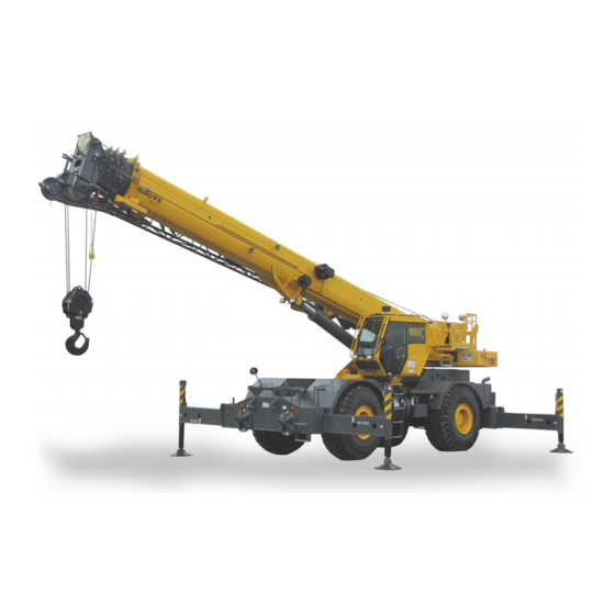
One boom is Manitowoc and our Dealer Network want to ensure your a v a i l a b l e o n t h e c r a n e ; a f i v e s e c t i o n , f u l l p o w e r, satisfaction with our products and customer support. -
Page 17: List Of Specifications
RT770E SERVICE MANUAL INTRODUCTION LIST OF SPECIFICATIONS Horse Power Rating. 179 kW (240 hp) @ 2500 rpm Oil Pan Capacity ....15.6 L (18.5 qt) Coolant System ....38 L (40 qt) General Axles Model . -
Page 18: Hoists
INTRODUCTION RT770E SERVICE MANUAL Hoists Drum Dimensions Diameter ....381 mm (15 in) Length (Standard) ..467 mm (18.38 in) Cable Diameter . - Page 19 RT770E SERVICE MANUAL INTRODUCTION Table 1-1Axle Weight Distribution Table CG From Rear Weight Front Axle Rear Axle Description Axle cm (in) kg (lb) kg (lb) kg (lb) Basic Unit Maximum Axle Loads Allowed 23360 (51500) 23360 (51500) Maximum Tire Loads Allowed 53600 (24312) 53600 (24312) Standard Carrier 4 x 4, w/O/R Beams, plus...
- Page 20 INTRODUCTION RT770E SERVICE MANUAL CG From Rear Weight Front Axle Rear Axle Description Axle cm (in) kg (lb) kg (lb) kg (lb) Substitutions, Deletions, and Removals from Basic Unit Weight Sub: Removable Ctwt System 229.13 (90.21) 375 (827) 211 (466) 164 (361) Sub: Add’l Hoist Access Platform Weight w/ -213.82 (-84.18)
-
Page 21: Crane Nomenclature
RT770E SERVICE MANUAL INTRODUCTION Crane Nomenclature 8251-1 8251-2 FIGURE 1-2 Published 11/26/2014, Control # 447-05 GROVE... - Page 22 INTRODUCTION RT770E SERVICE MANUAL Item Description Item Description Boom Nose Sheaves Fuel Tank Boom Crane Steps Work Lights Boom Pivot Pin Hydraulic Valves and Swing Motor Cover Air Conditioning Components Swingaway Extension Windshield Washer Fluid Container Auxiliary Boom Nose Hoist Access Platform (Fixed Counterweight Job Extension Units Only) Outrigger Pads...
-
Page 23: General Maintenance
RT770E SERVICE MANUAL INTRODUCTION GENERAL MAINTENANCE compressed air on bearings. Spinning bearings without lubricant will cause damage to the bearing, and could cause These general suggestions should be helpful in following the the bearing to fly apart. i ns t r u c t io n s i n th i s m a nu a l . I n a n al y z i ng a s y s te m malfunction, use a systematic approach to locate and correct the problem. -
Page 24: Pressing Parts
INTRODUCTION RT770E SERVICE MANUAL Pressing Parts Hoses and Tubes When pressing one part into another, use an anti-seize DANGER compound or a molybdenum disulfide base compound to lubricate the mating surfaces. High Pressure/Temperature Hazard! Assemble tapered parts dry. Before assembling parts with Exercise extreme care around pressurized hydraulic tapered splines, be sure the splines are clean, dry, and free hoses or tubes. -
Page 25: Bearings
RT770E SERVICE MANUAL INTRODUCTION Installation assembly to obtain accurate pre-loading. When installing a bearing, spacer, or washer against a shoulder on a shaft, be When installing a new hose, loosely connect each end sure the chamfered side is toward the shoulder. and make sure the hose takes up the designed position When pressing bearings into a retainer or bore, uniformly before tightening the connection. -
Page 26: Hydraulic Systems
If any of the above conditions exist, evaluate hose assemblies for correction or replacement. For replacement Contaminants in a hydraulic system affect operation and will of hose assemblies, refer to your Manitowoc Crane Care result in serious damage to the system components. Dirty Parts Manual. -
Page 27: Hydraulic Fittings
Flats from Finger Tight (F.F.F.T.) Method Optionally for future tightening of the same connection: Manitowoc recommends that the F.F.F.T. tightening method extend the line from the nut at its new location onto the described here be used when assembling all hydraulic hex of the static fitting or port (Figure 1-4). -
Page 28: Electrical System
INTRODUCTION RT770E SERVICE MANUAL Table 1-4: Adjustable Straight Thread O-ring Fittings Make sure both threads and sealing surfaces are free of burrs, nicks, scratches or any foreign particles. Lubricate O-ring with clean oil (Figure 1-6). Non-Adjustable Fitting to Port FIGURE 1-6 a0032 Turn fitting until finger tight. -
Page 29: Fatigue Of Welded Structures
Loctite® are specified throughout the Service • Salt water conditions after 8,000 hours of service. Manual. The following types of Loctite® brand adhesives are available from the Parts Department of the local Manitowoc Fatigue of Welded Structures distributor. -
Page 30: Fasteners And Torque Values
When using a torque wrench, any erratic or The torque tables are provided by Manitowoc for reference jerking motion can result in the application of excessive or when performing maintenance. - Page 31 RT770E SERVICE MANUAL INTRODUCTION SAE Grade 1 SAE Grade 5 SAE Grade 7 SAE Grade 8 and Grade 2 HHCS HHCS HHCS HHCS Socket Head Socket Head Serrated Capscrew Shoulder Flange Head Screw FIGURE 1-8 Table 1-6: UNC (Coarse) Thread: Torque Values for Zinc-Flake Coated and Untreated Fasteners Bolt Diameter - Inches Torque Values (Pounds-Foot, Maximum/Minimum) SAE Grade...
- Page 32 INTRODUCTION RT770E SERVICE MANUAL Table 1-8: Metric Fasteners, Coarse Thread, Zinc-Flake Coating Bolt Diameter - Metric Torque Values (Nm) Class 21.6 42.4 73.1 1195 1608 2072 10.9 12.5 31.5 62.0 1325 1800 2450 3150 12.9 15.0 36.0 75.0 1060 1550 2125 2850 3700...
-
Page 33: Weld Studs
RT770E SERVICE MANUAL INTRODUCTION Table 1-12: UNC (Coarse) Thread: Torque Values for Table 1-13: Metric Coarse Thread: Torque Values for Stainless Steel Fasteners with Oil Lubrication Stainless Steel Fasteners with Oil Lubrication Torque Value Torque Size Value Size lb-in lb-ft #5 (0.125) —... -
Page 34: Wire Rope
ANSI/ASME B30.5, federal regulations, and amount depends on the rope’s size, type, and anticipated Manitowoc. The inspection interval shall be determined by a use. This in-process treatment will provide the finished rope qualified person and shall be based on such factors as... -
Page 35: Wire Rope Inspection (Running Ropes And Pendant Cables)
When replacing fixed length cable assemblies (e.g. pendants) having permanently attached end fittings use only pre-assembled lengths of wire rope as supplied from Manitowoc. Do not build lengths from individual components. Replace an entire wire rope assembly. Do not attempt to rework damaged wire rope or wire rope ends. -
Page 36: Wire Rope Inspection (Boom Extension And Retraction Cables)
Wire Rope Inspection (Boom Extension and Standard as referenced by Federal Government Agencies Retraction Cables) and as recommended by Manitowoc. All wire rope will eventually deteriorate to a point where it is no longer usable. Periodic Inspection Wire rope shall be taken out of service when any of the... -
Page 37: Seizing Wire Rope
• Severe corrosion as evidenced by pitting. Method 2 • Manitowoc recommends that for cable extended booms, a single damaged wire rope assembly shall require replacement of the entire set of extension cables. • Manitowoc recommends for cable extended booms, that boom extension cables be replaced every seven (7) years. -
Page 38: Installing 35X7 Class Wire Rope
INTRODUCTION RT770E SERVICE MANUAL seriously damage the rope.) The tensioning load should range from 1 to 2% of the rope’s minimum breaking force. For ropes in multi-part systems: Reeve the traveling block and boom tip sheaves so the rope spacing is maximized and the traveling (hook) block hangs straight and level to help assure block stability. - Page 39 RT770E SERVICE MANUAL INTRODUCTION NOTE: The outer strands must not be able to move with respect to the inner strands. The weld must not exceed the diameter of the rope. b. If a welder is not available, the cut is to be made with an acetylene torch.
- Page 40 INTRODUCTION RT770E SERVICE MANUAL THIS PAGE BLANK 1-26 Published 11/26/2014, Control # 447-05...
-
Page 41: Section 2
RT770E HYDRAULIC SYSTEM SECTION 2 HYDRAULIC SYSTEM SECTION CONTENTS Description ....... 2-2 Procedure H - PreCharging The Accumulator . -
Page 42: Description
HYDRAULIC SYSTEM RT770E Description ......2-55 Lift Cylinder ......2-64 Description . -
Page 43: Hydraulic Symbols
RT770E HYDRAULIC SYSTEM HYDRAULIC SYMBOLS The following pages show basic hydraulic symbols as use on the schematics. Description Symbol Description Symbol Hydraulic Reservoir - Stores, cools, and Filter - Removes contamination from cleans machines hydraulic fluid supply. hydraulic fluid. Hydraulic Return Lines - Terminated at (1) Filter with Bypass Valve - Bypass valve below fluid level (2) above fluid level. - Page 44 HYDRAULIC SYSTEM RT770E Description Symbol Description Symbol Single Acting Cylinder - Extended Manually Operated - Valve shifted hydraulically and retracted with a spring. manually with check to allow flow back to tank. Double Acting Cylinder - Extended and retracted hydraulically. Double Acting Telescope Cylinder - Anchored rod pushes Pneumatic Operated - Valve shifted by barrel out when check valve is unseated.
-
Page 45: Maintenance
Use only port for the side walls to drain. Manitowoc supplied parts to repair the crane. Clean and install the reservoir plug and fill the reservoir Hydraulic System Maintenance Precautions with a 50/50 mixture of fuel oil and clean hydraulic oil. -
Page 46: Removing Air From The Hydraulic System
HYDRAULIC SYSTEM RT770E Disconnect the return line from an outrigger extension 26. Repeat Steps 24 and 25 for the auxiliary hoist as cylinder and fully extend the outrigger. necessary. Connect the outrigger return line and retract the 27. Disconnect one of the lines from the swing motor and outrigger. -
Page 47: Parts Replacement
RT770E HYDRAULIC SYSTEM Directional Control Valves Operate all hydraulic circuits several times in both directions. The control valves that control the crane functions are • This action should return any entrapped air to the installed on the right side of the turntable. reservoir where it can be removed from the hydraulic oil Inspection by the baffles. -
Page 48: Visual Inspection Of Hoses And Fittings
For replacement temperatures will negatively impact service life. Therefore it of hose assemblies, refer to your Manitowoc Crane Care is recommended for these hoses to be inspected thoroughly Parts Manual. -
Page 49: Supply Pressure And Return Circuit
RT770E HYDRAULIC SYSTEM SUPPLY PRESSURE AND RETURN CIRCUIT A filler neck and breather on the top of the reservoir are for filling the reservoir and for venting it. The filler neck includes Description a strainer for catching contaminants and gaskets to prevent leaking. -
Page 50: Pump Distribution
HYDRAULIC SYSTEM RT770E Section two of the No. 1 hydraulic pump supplies the rear Item Description axle oscillation lockout valve and the integrated outrigger/ Temperature Switch- Low Fan Speed rear steer valve. Temperature Switch-High Fan Speed Output from pump number 1, section 2 passes through a priority flow control valve for the hydraulic oil cooler motor Hydraulic Tank and the high speed boost selector valve. - Page 51 RT770E HYDRAULIC SYSTEM Symptom Probable Cause Solution Slow response. Low hydraulic oil level. Check system for leaks. Make repairs as needed. Fill reservoir. b. Hydraulic oil temperature too high b. If too low, warm up system. As (watery thin oil) or too low (thick needed, troubleshoot cooler circuit.
-
Page 52: Troubleshooting Aids
HYDRAULIC SYSTEM RT770E Troubleshooting Aids or ballooned hoses, leakage around the hydraulic components, etc. Hydraulic schematics - an exact illustration of the Second, make an analysis of symptoms. The function of arrangement of the system. The schematic shows all the each component in the system must be known before a components in relation to the system. -
Page 53: Hydraulic Oil Return Filter Assembly
RT770E HYDRAULIC SYSTEM Hydraulic Oil Return Filter Assembly Remove and discard the O-ring between the cap and the return filter head. The hydraulic oil return filter assembly (see Figure 2-1 and Remove the element from the return filter head. Figure 2-2) is located in the reservoir. It bolts to the top of the reservoir, and its bypass outlet fits into a tube welded in the Element Installation reservoir. - Page 54 HYDRAULIC SYSTEM RT770E 7834 FIGURE 2-2 Item Description Item Description Filter Head O-ring Bowl, w/Extension Capscrew Gauge Assembly Bypass Valve Assembly Square O-ring Spacer Gasket Capscrew Element Washer 2-14 Published 11/26/2014, Control # 447-05...
-
Page 55: Oil Cooler
RT770E HYDRAULIC SYSTEM OIL COOLER the oil cooler fan motor to high. The hydraulic oil high temperature indicator switch is normally closed and will open Description when the hydraulic oil temperature reaches 87.8°C (190°F), causing the CAN bus system to turn on the hydraulic oil high An air cooled hydraulic/transmission oil cooler (Figure 2-3) is temperature indicator in the gauge cluster to alert the located next to the hydraulic tank. - Page 56 HYDRAULIC SYSTEM RT770E 7839 FIGURE 2-3 Item Description Item Description Outlet Port Temperature Switch Fan Motor Transmission Oil Cooler Inlet Port Hydraulic Oil Cooler Drain Port 2-16 Published 11/26/2014, Control # 447-05...
-
Page 57: Hydraulic Pumps
RT770E HYDRAULIC SYSTEM HYDRAULIC PUMPS CAUTION Description Keep the pump as level as possible to avoid damaging The No. 1 and No. 3 hydraulic pumps Figure 2-4 are the input spline. mounted on a drive pad of the torque converter. The No. 2 hydraulic pump Figure 2-4 is mounted on a drive pad of the Remove the capscrews and washers attaching the No. - Page 58 HYDRAULIC SYSTEM RT770E and its gasket into place so they seat properly on the pump disconnect assembly. CAUTION Secure pump drive assembly and pump to torque Keep the pump as level as possible to avoid damaging converter drive pad with nuts and washers. Torque nuts; the input spline.
- Page 59 RT770E HYDRAULIC SYSTEM Install pump and gasket on engine drive pad with Install pump and gasket on torque converter drive pad capscrews and washers. Make sure the splines mesh with capscrews and washers. Make sure the splines properly. Torque capscrews; refer to Fasteners and mesh properly.
- Page 60 HYDRAULIC SYSTEM RT770E Place your hand on the pump to check for excessive If the pump seems to be running properly, increase the heat buildup caused by binding or other problems. If the RPM to 1500 to 1800 rpm for one to two minutes while pump is too hot to keep a hand on, stop the engine.
-
Page 61: Pump Disconnect Assembly
RT770E HYDRAULIC SYSTEM Remove oil seals from housing. Item Description Assembly Engine Install two oil seals into holes in housing. Transmission Pin shifter assembly in housing with shaft. Hydraulic Pump No. 3 Pin collar to shaft with roll pin. Hydraulic Pump No. 1 Install shifter lock on handle. - Page 62 HYDRAULIC SYSTEM RT770E 7530 7528 FIGURE 2-5 Item Description Item Description Pump Disconnect Assembly Shifter Assembly Housing Shifter Lock Shaft Roll Pin Oil Seal Plug Handle Pipe Plug Collar Engine 2-22 Published 11/26/2014, Control # 447-05...
-
Page 63: Pressure Setting Procedures
RT770E HYDRAULIC SYSTEM PRESSURE SETTING PROCEDURES NOTE: When checking the directional control valve relief settings, unless otherwise specified, start with the The following procedures should be used to properly check, engine at idle RPM and move the controller to its adjust and set the hydraulic system pressures. -
Page 64: Procedure A - Main Control Valve Reliefs
HYDRAULIC SYSTEM RT770E Procedure A - Main Control Valve Reliefs Install pressure check diagnostic quick disconnect with gauge onto test nipple at main directional control valve inlet gauge port Figure 2-7. Completely extend lift cylinder (or cap hose from “A” port to the lift cylinder), attempt to lift up with engine running Disconnect at full RPM. -
Page 65: Procedure B - Main Directional Control Valve Pilot Supply Pressure
RT770E HYDRAULIC SYSTEM Disconnect and cap the hose running from the main to increase or counterclockwise to decrease the directional control valve to the hoist(s) port “A” on the pressure setting. hoist motor control valve. Disconnect the hoist brake Remove pressure gauge from the pilot supply test port. release line at the hoist Figure 2-6. -
Page 66: Procedure E - Charge Air Cooler Valve Relief Pressure
HYDRAULIC SYSTEM RT770E CAC Solenoid CF1 Port Test Port CF2 Port 7798 Adjustable Inlet Adjustable Relief Valve CAC Fan Relief Valve FIGURE 2-9 Procedure E - Charge Air Cooler Valve Relief Pressure Install pressure check diagnostic quick disconnect (Parker PD240) with gauge onto Test Port, Figure 2-9. Unplug CAC Solenoid. -
Page 67: Procedure H - Precharging The Accumulator
RT770E HYDRAULIC SYSTEM Turn the gas chuck “T” handle all the way down brake pedal on the cab floor several times. Remove the (clockwise) which will depress the core in the gas valve. gas valve guard and gas valve cap on the accumulator Figure 2-11. -
Page 68: Procedure J - Front Steer Relief Valve Pressure
HYDRAULIC SYSTEM RT770E Remove pressure gauge from the pressure check port. 7531-1 FIGURE 2-12 Outrigger/rear steer adjustable relief: Loosen jam nut and turn stem in (CW) to increase or out (CCW) to decrease Item Description pressure. FIGURE 2-13 Steer Priority Swing “A”... -
Page 69: Procedure M - Counterweight Removal Valve
RT770E HYDRAULIC SYSTEM Procedure M - Counterweight Removal Valve Install pressure check diagnostic quick disconnect with gauge onto test nipple at main directional control valve 7532-3 load sense relief test port Figure 2-7. With engine at full RPM, retract counterweight cylinder and set relief valve on counterweight valve Figure 2-15 to 121 bar ±4 (1750 psi ±50);... -
Page 70: Valves
HYDRAULIC SYSTEM RT770E VALVES location, refer to Table 2-3. Refer to Figure 2-16 and Figure 2-17 for valve locations. General The description of each valve given here is for the valve itself. For information on how each valve functions in the This subsection provides descriptive information for several individual circuits, refer to the description and operation of the main hydraulic valves used on this crane. - Page 71 RT770E HYDRAULIC SYSTEM Rear Valve Installation - Carrier FIGURE 2-16 Item Description Item Description Front Outrigger Control Valve Park Brake Range Shift Valve Integrated Outrigger/Rear Steer Valve Differential Lock Valve (Optional) Fan Bypass Valve Axle Lockout Valve Priority Flow Divider Valve Rear Outrigger Control Valve Adjustable Flow Valve 2-31...
- Page 72 HYDRAULIC SYSTEM RT770E Superstructure FIGURE 2-17 Item Description Item Description Counterweight Removal Manifold Steering Priority/Swing Control Valve Directional Control Valve (Hoist/Lift/Tele) Dual Accumulator Control Valve Swing Brake and Armrest Lockout Manifold Telescope Fill Control Manifold 2-32 Published 11/26/2014, Control # 447-05...
-
Page 73: Directional Control Valves
RT770E HYDRAULIC SYSTEM DIRECTIONAL CONTROL VALVES Swing/Steer Directional Valve Installation Install the valve on the turntable upright and secure with Description the capscrews, flatwashers, lockwashers and bushings. Torque capscrews; refer to Fasteners and Torque The directional control valves direct and control hydraulic oil Values, page 1-16 for proper torque value. - Page 74 HYDRAULIC SYSTEM RT770E 3, 12 16 17 25 18 19 23 26 27 Main Hoist/Aux Hoist/Lift/Telescope Valve Assembly FIGURE 2-18 2-34 Published 11/26/2014, Control # 447-05...
- Page 75 RT770E HYDRAULIC SYSTEM Item Description Item Description Load Sense Gauge Port Port 4A - Lift Extend From Pump Port 4B - Lift Retract Gauge Port Relief Valve - Auxiliary Hoist Up Main Hoist Directional Valve Relief Valve - Telescope Extend Auxiliary Hoist Directional Valve Relief Valve - Telescope Retract Telescope Directional Valve...
- Page 76 HYDRAULIC SYSTEM RT770E 2200 2200 2500 6671-3A 6671-2 Swing/Steer Valve Assembly FIGURE 2-19 Item Description Item Description Port 1A - Load Sense Port 2B - Work Port Port 1B - Priority Flow Steer Priority Flow Divider Inlet Port Swing WP Relief Valve Outlet Port Swing WP Relief Valve Port 2A - Work Port...
- Page 77 RT770E HYDRAULIC SYSTEM 7532-1 7532-3 7532-2 Counterweight Removal Manifold FIGURE 2-20 Item Description Item Description Port P - Pressure to Directional Valve Port 1B - Solenoid Valve SV1 Port LS - Load Sense Port 2B - Solenoid Valve SV3 Port T - Tank to Swivel Port #4 Port 2A - Solenoid Valve SV4 Pressure Compensated Regulator Load Shuttle...
-
Page 78: Hydraulic Remote Control Valve
HYDRAULIC SYSTEM RT770E HYDRAULIC REMOTE CONTROL VALVE NOTE: If the crane is equipped with an optional auxiliary hoist, the auxiliary hoist function replaces the Description telescope function on the control lever of the left armrest and the telescope function is controlled by The crane has four single axis hydraulic remote control a pedal operated single function control valve valves (Figure 2-21). - Page 79 RT770E HYDRAULIC SYSTEM Telescope Pedal Control Valve Removal (With Connect the pedal linkage to the control valve with the pin and cotter pin. Auxiliary Hoist Option) Disconnect the pedal linkage from the control valve by Telescope Pedal Control Valve Functional Check removing the pin and cotter pin.
- Page 80 HYDRAULIC SYSTEM RT770E NOTE: R.H. and L.H. controllers oriented from seated operator. Ports of control lever seen facing aft looking at seat with armrest in up position. 4, 8, 12 7393-2 3, 7, 11 7393-1 5, 9 6, 10 AUX HOIST/ TELESCOPE BOOM SWING...
- Page 81 RT770E HYDRAULIC SYSTEM Dual Axis Item Description Tank Port 4, 8 5, 9 Pump Port Port B2 - Swing Left Port B1 - Swing Right Port A1 - Auxiliary Hoist Cable In Port A2 - Auxiliary Hoist Cable Out Port B2 - Boom Lift Up Port B1 - Boom Lift Down 3, 7 Port A1 - Main Hoist - Cable In...
-
Page 82: Dual Accumulator Charge Valve
HYDRAULIC SYSTEM RT770E DUAL ACCUMULATOR CHARGE VALVE Maintenance Removal Description Tag and disconnect the hydraulic hoses from the valve. The load sensing dual accumulator charging valve is located Cap or plug the lines and ports. on the inside of the left superstructure side plate. The purpose of the valve is to provide pressure regulation to the Remove the three bolts, washers, and lockwashers service brake circuit. - Page 83 RT770E HYDRAULIC SYSTEM 7752-02 7752-01 These ports plugged Item Description Load Sense Port Tank Port Pressure Port Accumulator Port 1A Accumulator Port 2A Pressure Switch 7752-03 Valve Hydraulic Schematic FIGURE 2-24 2-43 GROVE Published 11/26/2014, Control # 447-05...
-
Page 84: Swing Brake And Armrest Lockout Valve
HYDRAULIC SYSTEM RT770E SWING BRAKE AND ARMREST LOCKOUT lockwashers. Torque capscrews; refer to Fasteners and Torque Values, page 1-16 for proper torque value. VALVE MANIFOLD Connect the hydraulic lines to the manifold as tagged Description during removal. The swing brake and armrest lockout valve manifold Connect the electrical connectors to the manifold as Figure 2-25 is located on the right side of the turntable. - Page 85 RT770E HYDRAULIC SYSTEM 7540-1 7540-2 FIGURE 2-25 Item Description Item Description Port P - Inlet Port Port REG 2 - Controller Armrest Lockout Valve Port G - Gauge Port Drain Port REG 1 - Swing Brake Release 2-45 GROVE Published 11/26/2014, Control # 447-05...
-
Page 86: Holding Valve
HYDRAULIC SYSTEM RT770E HOLDING VALVE CAUTION Description Do not damage the O-rings during installation of the A bolt-on externally piloted manifold style holding valve is holding valve. If the holding valve turns freely then gets installed on the lift cylinder and a cartridge style holding valve hard to turn, then easy to turn, remove the holding valve is installed into each telescope cylinder port block. -
Page 87: Outrigger/Rear Steer Valve
RT770E HYDRAULIC SYSTEM OUTRIGGER/REAR STEER VALVE either the outriggers or the rear steer energizes the solenoid valve to close and allow oil to flow to the selected circuit. Description The rear steer section contains a three position four-way solenoid controlled directional valve. The outrigger/rear steer valve Figure 2-26 controls the outrigger circuit and the rear steer circuit. -
Page 88: Maintenance
HYDRAULIC SYSTEM RT770E Remove the capscrews, nuts, and washers securing the valve to the frame. Remove the valve as a complete Item Description assembly. Port T - Tank Installation Port P - Pressure from High Speed Boost Install the integrated outrigger/rear steer valve to the Selector Valve f r a m e . -
Page 89: Outrigger Control Manifold
RT770E HYDRAULIC SYSTEM OUTRIGGER CONTROL MANIFOLD closed two position two way solenoid valve assemblies, one for each cylinder. They are mounted inside the frame on their Description respective outrigger box. Each solenoid valve contains a manual override actuator which allows the valve to be There are two outrigger control manifolds Figure 2-27 opened if there is a loss of electrical power. -
Page 90: Maintenance
HYDRAULIC SYSTEM RT770E Maintenance Installation Position the manifold on the outrigger box and secure Removal with the washers, hex nuts, and capscrews. Torque Tag and disconnect the hydraulic lines to the solenoid capscrews; refer to Fasteners and Torque Values, page valves;... -
Page 91: Parking Brake/Range Shift Valve
RT770E HYDRAULIC SYSTEM PARKING BRAKE/RANGE SHIFT VALVE Maintenance Description Removal The parking brake/range shift valve controls the flow of oil to Tag and disconnect the electrical connectors to the the parking brake, hi-low range and axle disconnect valve. actuators by the use of two solenoid valves Figure 2-28. The Tag and disconnect the hydraulic hoses from the valve. - Page 92 HYDRAULIC SYSTEM RT770E 6697-2 Hydraulic Schematic 6697-1 FIGURE 2-28 Item Description Item Description Port P - Pressure Port PB - To Park Brake Port T - Tank Solenoid Valve - Range Shift Port A - Range Shift Actuator Solenoid Valve -Park Brake Port B - Range Shift Actuator Pressure Switch 2-52...
-
Page 93: Axle Oscillation Lockout Valve
RT770E HYDRAULIC SYSTEM AXLE OSCILLATION LOCKOUT VALVE hydraulic oil cannot leave the cylinders. Instead, the cylinders remain full of hydraulic oil and more rigid. Description When the axle oscillation solenoid valves are energized and open, hydraulic oil is allowed in and out of the cylinders, The axle oscillation lockout valve Figure 2-29 (also called the allowing them to oscillate. -
Page 94: High Speed Boost Selector Valve
HYDRAULIC SYSTEM RT770E HIGH SPEED BOOST SELECTOR VALVE Maintenance Removal Description Tag and disconnect the electrical connectors to the The high speed boost selector valve Figure 2-30 is located valve. on port #6 of the hydraulic swivel spool. Output from pump number 1, section 2 passes through the high speed boost Tag and disconnect the hydraulic hoses from the valve. -
Page 95: Telescope Stage Selector Valve Manifold
RT770E HYDRAULIC SYSTEM TELESCOPE STAGE SELECTOR VALVE controlled, four-way directional control valve (2); and two shuttle valves (3). The oil flow from the Telescope Directional MANIFOLD Control Valve is split after entering the Telescope Stage Selector Valve Manifold and goes to the two poppet valves. Description One poppet valve controls oil flow to the first stage and the The software sends output signals to the Telescope Stage... -
Page 96: Telescope Fill Tube Control Valve Manifold
HYDRAULIC SYSTEM RT770E TELESCOPE FILL TUBE CONTROL VALVE first stage is maintained at two pressure settings by a solenoid controlled relief valve (3). As the second stage MANIFOLD extends, the RCL, based on inputs from the cylinder length sensing components, will cause the relief valve to maintain a Description low pressure (<... -
Page 97: Maintenance
RT770E HYDRAULIC SYSTEM Maintenance Installation Secure the valve to the frame with the nuts, flatwashers, Removal lockwashers and capscrews. Torque capscrews; refer to Fasteners and Torque Values, page 1-16 for proper Tag and disconnect the electrical connectors to the torque value. valve. -
Page 98: Hydraulic Accumulator
HYDRAULIC SYSTEM RT770E HYDRAULIC ACCUMULATOR Remove the two nuts securing each clamp half. Remove each clamp half and accumulator from the turntable. Description Installation The hydraulic accumulators are located inside the Position the accumulator in the clamps and secure with superstructure on the left side under the main hoist. -
Page 99: Service Brake And Cac Fan Motor Priority
RT770E HYDRAULIC SYSTEM SERVICE BRAKE AND CAC FAN MOTOR Removal PRIORITY FLOW CONTROL VALVE Tag and disconnect the hydraulic lines attached to the valve. Cap or plug the lines and ports. Description Remove the capscrews, washers, flatwashers and nuts The priority flow control valve is located inside the left frame securing the valve to the valve mounting plate and rail at the center of the frame. -
Page 100: Oil Cooler Fan Motor Priority Flow Control
HYDRAULIC SYSTEM RT770E OIL COOLER FAN MOTOR PRIORITY FLOW Start the crane and energize the high speed boost and operate the crane several times. Verify the hydraulic oil CONTROL VALVE cooler fan motor works properly. Description Check for leaks. Make repairs as needed. The priority flow control valve is located inside the right frame Procedure for checking Hydraulic Oil Cooler Fan rail at the center of the frame. -
Page 101: Cylinders
Fully retract the cylinder rod (except the telescope protected using Boeshield® T-9 Premium Metal Protectant. cylinder). Remove the extend hose from the cylinder. Manitowoc Crane Care has Boeshield® T-9 Premium Metal Cap the extend hose. Protectant available in 12 oz. aerosol cans by ordering part number 9999101803. -
Page 102: Temperature Effects On Hydraulic Cylinders
HYDRAULIC SYSTEM RT770E Apply hydraulic pressure to the retract (rod) side of the boom may be undetected by the operator unless a load is cylinder and observe the open cylinder port for leakage. suspended for a long period of time. To minimize the effects of thermal contraction or “Stick-slip”... - Page 103 RT770E HYDRAULIC SYSTEM Table 2-5 Boom Drift Chart (Cylinder length change in inches) Coeff. = 0.00043 (in / °F) STROKE Temperature Change (°F) (FT.) 0.26 0.52 0.77 1.03 1.29 1.55 1.81 2.06 2.32 2.58 0.52 1.03 1.55 2.06 2.58 3.10 3.61 4.13 4.64...
-
Page 104: Lift Cylinder
HYDRAULIC SYSTEM RT770E LIFT CYLINDER CAUTION Description When removing seals and rings, avoid scratching the The lift cylinder Figure 2-34 has a bore of 12.0 in (30.5 cm). grooved and gland surfaces. The retracted length of the cylinder from the center of the barrel bushing to the center of the rod bushing is 118.75 in Remove the two hydrolock seals from the outside of the (301.6 cm). - Page 105 RT770E HYDRAULIC SYSTEM FIGURE 2-34 Item Description Item Description Barrel Holding Valve Retaining Ring Piston Seal Assembly Head Not Used 2-65 GROVE Published 11/26/2014, Control # 447-05...
- Page 106 HYDRAULIC SYSTEM RT770E Item Description T-Seal O-ring, Low Temperature Back-up Ring Wear Ring Seal Rod Seal FIGURE 2-35 Back-up Ring Wiper Ring Item Description Capscrew Buffer Seal Deep Z Rod Seal Insert Capscrew Backup RIng Flatwasher Wiper Ring O-ring Plug Install the replacement wear rings, buffer seal and deep Z rod seal in the inside of the head.
- Page 107 RT770E HYDRAULIC SYSTEM 15. Screw the head retainer ring into the barrel and align holes in retainer ring with holes in head. Secure the CAUTION head retainer ring to the head with two socket head capscrews. Torque screws to 60 to 65 Nm (44 to 48 lb- Exercise extreme care when handling the rods.
-
Page 108: Telescope Cylinder
HYDRAULIC SYSTEM RT770E TELESCOPE CYLINDER Description The boom telescope cylinder is not field serviceable and must be returned to the manufacturer for repair. The cylinder, with oil, weighs approximately 1745 kg (3847 lb), retracted. Maintenance For removal and installation instructions refer to Boom, page 4-1. -
Page 109: Axle Oscillation Lockout Cylinder
RT770E HYDRAULIC SYSTEM AXLE OSCILLATION LOCKOUT CYLINDER Turn the head counterclockwise with a fitted spanner wrench until the threads disengage. Description NOTE: Residual oil will spill over the end of the barrel. Make Provisions to contain the oil. The oscillation lockout cylinder Figure 2-37 has a 12.7 cm (5 in) diameter bore. - Page 110 HYDRAULIC SYSTEM RT770E 6731 FIGURE 2-37 Item Description Item Description Lip Seal Barrel Wiper Ring Retainer Ring Head Bleeder Plug Lip Seal Grease Fitting Wear Ring Grease Fitting O-ring Setscrew Backup Ring O-ring Wear Ring Buffer Seal 2-70 Published 11/26/2014, Control # 447-05...
- Page 111 RT770E HYDRAULIC SYSTEM Clean all oil from the threads of the head. Coat the threads with an anti-seize compound (ex: Never-Seez CAUTION paste lubricant or similar lubricant). Before installing new seals and rings, clean all surfaces Slide the head onto the rod. The head will have to be and carefully remove burrs and nicks.
-
Page 112: Steer Cylinder
HYDRAULIC SYSTEM RT770E STEER CYLINDER NOTE: Residual oil will spill over the end of the barrel. Make provisions to contain the oil. Description Using a hoist, extend the rod assembly slowly until the piston is free of the barrel. The steer cylinders Figure 2-38 are mounted on the axles, two cylinders on each axle. - Page 113 RT770E HYDRAULIC SYSTEM 7548 FIGURE 2-38 Item Description Item Description O-ring Locknut O-ring Retainer Ring Backup Ring Grease Fitting Wiper RIng Barrel Seal O-ring Piston Seal Head Wear Ring 2-73 GROVE Published 11/26/2014, Control # 447-05...
- Page 114 HYDRAULIC SYSTEM RT770E Assembly Push the head about half way down the length of the rod assembly.Install the spacer and piston onto the rod. Install the locknut on the rod. CAUTION With the hoist, raise the rod assembly back into a When installing new seals and rings, avoid stretching vertical position taking care not to damage the OD of the seals or scratching the grooved or gland surfaces.
-
Page 115: Outrigger Extension Cylinder
RT770E HYDRAULIC SYSTEM OUTRIGGER EXTENSION CYLINDER Place the rod assembly horizontally on a workbench taking care not to damage the surface of the rod. Cover Description the open end of the barrel to avoid contamination. Remove the locknut from the rod. The extension cylinder Figure 2-39 has a 63.5 mm (2.5 in) diameter bore. - Page 116 HYDRAULIC SYSTEM RT770E 6931 FIGURE 2-39 Item Description Item Description Barrel O-ring O-ring Piston Backup Ring Head Rod Seal Spacer Wiper Ring Wear Ring Piston Seal Wear Ring 2-76 Published 11/26/2014, Control # 447-05...
- Page 117 RT770E HYDRAULIC SYSTEM Stone out minor blemishes and polish with a fine crocus Slide the head onto the rod. The head will have to be cloth. tapped on with a rubber mallet to engage the seals. Push the head about half way down the length of the rod Clean with solvent and dry with compressed air any assembly.
-
Page 118: Outrigger Jack Cylinder
HYDRAULIC SYSTEM RT770E OUTRIGGER JACK CYLINDER NOTE: Do not extend the rod completely. Oil or oil/air mixture may rapidly exit out of the ports during Description extension. Shield the work area from the exiting oil. Turn the head counterclockwise with a fitted spanner The outrigger jack cylinder Figure 2-40 has a 11.4 cm (4.5 in) wrench until the threads disengage. - Page 119 RT770E HYDRAULIC SYSTEM 7, 8 6801 FIGURE 2-40 Item Description Item Description Barrel Backup Ring O-ring Head Wiper Ring Piston Rod Seal Spacer Buffer Seal Check Valve Wear RIng Setscrew O-ring Nylon Insert Backup Ring Plug Seal 2-79 GROVE Published 11/26/2014, Control # 447-05...
- Page 120 HYDRAULIC SYSTEM RT770E Assembly 11. Continue turning the head counterclockwise until the thread clicks, then reverse direction to clockwise and thread in until there is no gap between the head CAUTION shoulder and the top of the barrel. When installing new seals and rings, avoid stretching 12.
-
Page 121: Counterweight Removal Cylinder
RT770E HYDRAULIC SYSTEM COUNTERWEIGHT REMOVAL CYLINDER NOTE: Arranging discarded seals and rings in the order of disassembly will aid in installation of new seals and Description rings. Pay attention to how each seal and ring is installed to avoid installing replacement seals and The counterweight cylinder Figure 2-41 has a 8.9 cm (3.5 in) rings improperly. - Page 122 HYDRAULIC SYSTEM RT770E 7347 FIGURE 2-41 Item Description Item Description Barrel O-ring Wear Ring Head Piston Seal O-ring Piston Backup Ring Spacer Rod Seal Wiper Ring Bolt Bleeder Plug Locknut Plug Holding Valve O-ring 2-82 Published 11/26/2014, Control # 447-05...
- Page 123 RT770E HYDRAULIC SYSTEM Install the rod seal, wiper ring and O-ring in the inside of 11. Install new O-rings onto the holding valve. the head. 12. Lubricate the holding valve and O-rings with clean Install the O-ring and backup ring on the outside of the hydraulic oil.
- Page 124 HYDRAULIC SYSTEM RT770E THIS PAGE BLANK 2-84 Published 11/26/2014, Control # 447-05...
- Page 125 RT770E SERVICE MANUAL ELECTRICAL SYSTEM SECTION 3 ELECTRICAL SYSTEM SECTION CONTENTS Description ....... 3-1 Relay Panel Component Replacement .
- Page 126 ELECTRICAL SYSTEM RT770E SERVICE MANUAL FIGURE 3-1 Published 11/26/2014, Control # 447-05...
-
Page 127: Batteries
RT770E SERVICE MANUAL ELECTRICAL SYSTEM Alternator The alternator (Figure 3-2) is mounted on the engine and is belt driven. It is a 145 ampere alternator with an integral transformer - rectifier unit. When the engine is running, and the alternator is turning, the alternator’s 12-volt output terminal supplies the crane’s electrical circuits. - Page 128 ELECTRICAL SYSTEM RT770E SERVICE MANUAL 7888-3 7888 FIGURE 3-4 7888-2 Figure 3-4 Item Numbers Item Component Item Component ACC Relay, CAB and T/T Modules Power(KS1) Diode Box ACC Relay, Jib Stow, RCL Override, Jib Option Fuse Box Relay, Windshield Wiper Low Speed Panel Screw Relay, Windshield Wiper High Speed Fast Pulse Buzzer Alarm...
-
Page 129: Carrier Electrical Panel
RT770E SERVICE MANUAL ELECTRICAL SYSTEM • Fuse 9 - Cab Control Modules Power Item Component • Fuse 10 - Turntable I/O Module Seat Harness Superstructure Harness • Fuse 11 - Turntable Power Module (Horn, Fan Motor) Overhead Harness • Fuse 12 - Turntable Power Module (AC Condenser Empty Motor, Boom Lights, Counterweight Removal - Option) Cab Interior Harness... - Page 130 ELECTRICAL SYSTEM RT770E SERVICE MANUAL Ignition key switch is in the ACC and RUN positions. ACC Relay #2 is not energized while in START position. 7860 Item Description ECM, 30 Amp Fuse (F1) Cranestar, 5 Amp Fuse (F2) Carrier, Rear Module, 25 Amp Fuse (F3) Carrier, Rear Module, 30 Amp Fuse (F4) Carrier, Front Module, 30 Amp Fuse (F5) Power Control Relay, 5 Amp Fuse (F6)
-
Page 131: Maintenance
If any of these conditions exist, evaluate the harness assemblies for repair or replacement. For replacement of harness assemblies, refer to your Manitowoc Crane Care DANGER Parts Manual. At the same service interval, visually inspect all Controller... -
Page 132: General Troubleshooting
Technology training course. shrinkable tubing or other suitable material to insulate the splice. Table 3-2 AMP Extraction Tool Table Description AMP Part Number Manitowoc Part Number 14 gauge wire (connectors) 305183 9999100176 12 to 8 gauge wire (connectors) 91019-3 9999100175... -
Page 133: Alternator/Charging System Troubleshooting
RT770E SERVICE MANUAL ELECTRICAL SYSTEM Description AMP Part Number Manitowoc Part Number 4 to 9 circuit (in-line connectors) 453300-1 15 circuit (in-line connectors) 458944-1 Table 3-3 AMP Crimping Tool Table Description AMP Part Number Manitowoc Part Number Tool Tool 14 to 12 gauge wire... - Page 134 ELECTRICAL SYSTEM RT770E SERVICE MANUAL Engine Off Tests Engine On Tests Batteries Output Voltage Test Connect multimeter to negative and positive battery terminals. DANGER Connect ammeter clamp around output wire of alternator to the batteries. Do not smoke or allow sparks or open flame near Start engine and increase speed to 2000 rpm.
-
Page 135: Alternator Replacement
RT770E SERVICE MANUAL ELECTRICAL SYSTEM If any voltage drop is greater than the normal range, Close the engine compartment. troubleshoot the system and repair any problems. Reconnect the ground cables to the battery. After correcting any problems, perform the Engine On Tests 10. -
Page 136: Battery Replacement
ELECTRICAL SYSTEM RT770E SERVICE MANUAL Battery Replacement Install the ECM power fuse. Turn the battery disconnect switch to ON. Removal Verify replacement batteries work by starting crane’s engine and operating various crane components. CAUTION Relay Panel Component Replacement To avoid possible engine fault codes and undesirable operation, ensure the keyswitch has been off 2 minutes Accessory Relay before disconnecting batteries. -
Page 137: Gauge Cluster Replacement
RT770E SERVICE MANUAL ELECTRICAL SYSTEM Gauge Cluster Replacement Install the left side cover (8) on the steering column. Secure the gauge/switch cover (6) to the left and right Use the following procedures and refer to Figure 3-9 when side covers (8, 9) using six screws (14). removing/installing the gauge cluster. -
Page 138: Ignition Switch Replacement
ELECTRICAL SYSTEM RT770E SERVICE MANUAL Inspection Check Visually check the switch for evidence of cracks, Operate the switch per the Operator’s Manual. Verify damaged connections, or other damage. Replace each of its functions works. damaged switch as needed. As needed, troubleshoot further any system or circuit Check wiring for damaged insulation or damaged malfunction not corrected by repair or replacement of connectors. -
Page 139: Turn Signal Lever And Transmission Shift Lever Replacement
RT770E SERVICE MANUAL ELECTRICAL SYSTEM b. Place switch at OFF or deactivated position. b. Remove the securing nut from the steering column Ohmmeter should register infinity (no continuity). shaft and remove the steering wheel (2). Replace switch if it fails either part of the check. Remove the four screws (13) securing the left and right side covers (8, 9) together. -
Page 140: Windshield Wiper Assembly Replacement
ELECTRICAL SYSTEM RT770E SERVICE MANUAL 7794-1 FIGURE 3-9 14. Install the lever (12) and spacer that locks/unlocks the Windshield Wiper Assembly Replacement steering column tilt/telescope function. Removal 15. Pull the rubber boot (11) up and over the bottom of the left and right side covers (8, 9). - Page 141 RT770E SERVICE MANUAL ELECTRICAL SYSTEM washer, and tapered sleeve securing the wiper arm to Install the motor bracket and attached parts in the cab the pivot shaft kit. (The nut, washer, and sleeve are part interior with attaching hardware. Ensure the pivot shaft of the pivot shaft kit.) sticks through the hole in the pantograph adapter kit.
-
Page 142: Windshield Washer Assembly Replacement
ELECTRICAL SYSTEM RT770E SERVICE MANUAL Windshield Washer Assembly Replacement Skylight Wiper Assembly Replacement Removal Removal Ensure that the key switch has been in the OFF position Ensure that the key switch has been in the OFF position for 2 minutes. for 2 minutes. -
Page 143: Tools For Troubleshooting
(Part No. 80026376). viscosity of the crane’s lubricants, always follow the cold Manitowoc Crane Care requests you have, as part of your weather start-up and operating procedures described in the service tool kit inventory, the CAN-Link service tool kit for the Operator Manual. - Page 144 If the heater remains faulty even after these points have heater while the crane engine is stopped, the been checked, or another malfunction occurs in your batteries voltage will need to be recharged after heater, contact an authorized Manitowoc distributor or short periods of time. Manitowoc Crane Care. Troubleshooting...
- Page 145 RT770E SERVICE MANUAL BOOM SECTION 4 BOOM SECTION CONTENTS Description ....... 4-1 Removal And Installation .
-
Page 146: Theory Of Operation
BOOM RT770E SERVICE MANUAL THEORY OF OPERATION telescope cylinder, and are secured to the rear of tele 3 on the other end; the tele 4 extension cables (qty 4) (9, Boom extension and retraction is accomplished with one Figure 4-1) are secured to the rear of tele 2 on one end, run two-stage telescope cylinder, 10 extension cables, and 6 around the extension sheaves on the front of tele 3, and are retraction cables. - Page 147 RT770E SERVICE MANUAL BOOM FIGURE 4-1 Published 11/26/2014, Control # 447-05 GROVE...
-
Page 148: Maintenance
BOOM RT770E SERVICE MANUAL MAINTENANCE Removal WARNING Ensure the lifting device is capable of supporting the NOTE: The boom assembly must be rotated 180° (upside boom assembly. Death or serious injury may result if the d o w n ) b e f o r e p e r f o r m i n g a n y a s s e m b l y o r lifting device cannot support the load. - Page 149 RT770E SERVICE MANUAL BOOM FIGURE 4-2 Published 11/26/2014, Control # 447-05 GROVE...
- Page 150 BOOM RT770E SERVICE MANUAL FIGURE 4-2 continued Published 11/26/2014, Control # 447-05...
- Page 151 RT770E SERVICE MANUAL BOOM FIGURE 4-2 continued Published 11/26/2014, Control # 447-05 GROVE...
- Page 152 BOOM RT770E SERVICE MANUAL FIGURE 4-2 continued Published 11/26/2014, Control # 447-05...
- Page 153 RT770E SERVICE MANUAL BOOM FIGURE 4-2 continued Published 11/26/2014, Control # 447-05 GROVE...
- Page 154 BOOM RT770E SERVICE MANUAL FIGURE 4-2 continued 4-10 Published 11/26/2014, Control # 447-05...
- Page 155 RT770E SERVICE MANUAL BOOM Item Description Item Description 46 Male 90 Deg Elbow ORFS/BSPP Base Section Weld 47 Pipe Clamp - 1/2””I.D. Tele-1 Weld 48 Tube Assy Tele 2 Weld 49 Tube Assy Tele 3 Weldment 50 Pipe Clamp Tele 4 Weld 51 Male 90 Deg Elbow ORFS/BSPP Cylinder, Telescope 52 Tube Assy...
- Page 156 BOOM RT770E SERVICE MANUAL Item Description Item Description 91 Front Lower Wear Pad Tele 2 136 Tele Sheave Mgt Weld 92 Upper Wear Pad Assy Tele 2 137 F Washer 3/4”” Hard ASTM F-436- 93 HHCS M20x100 8.8 ISO 4017 138 HHCS M20x50 10.9 ISO 4014 94 Rear Upper Wear Pad 139 Sheave Assy...
-
Page 157: Disassembly
RT770E SERVICE MANUAL BOOM Disassembly 12. Remove the two bolts (20) and flat washers (16) securing the plate (12) to the inside of the base section NOTE: The boom assembly must be rotated 180° (upside (1) (left and right sides). d o w n ) b e f o r e p e r f o r m i n g a n y a s s e m b l y o r 13. - Page 158 BOOM RT770E SERVICE MANUAL 20. Remove the four nuts (75) and two flat washers (74) securing the two bolts (76), which pass through the anchor plate (73), to the rear of tele 1 (2) (see Figure 4-4). 8008-30 FIGURE 4-5 27.
- Page 159 RT770E SERVICE MANUAL BOOM 34. Remove the wear pad (94)/grease hose assembly (81, 39. Remove the two bolts (76) from the anchor plate (73) 79, 80, 77, 78) from the attaching bracket on each side (see Figure 4-9). of the rear of tele 2 (3) (see Figure 4-7). 8008-24 FIGURE 4-9 8008-28...
- Page 160 BOOM RT770E SERVICE MANUAL 8008-23 FIGURE 4-11 8008-21 FIGURE 4-13 43. Remove the trunnion plate (60) from the front square lug of the telescope cylinder (6) (left and right sides) (see 45. Coil the four tele 3 retract cables (65) and set them on Figure 4-12).
- Page 161 RT770E SERVICE MANUAL BOOM cables (65) to the rear of tele 3 (4) (left and right sides) (see Figure 4-16). 8008-18 FIGURE 4-15 49. Remove the bolts (19), flat washers (16), lock washers 8008-15 FIGURE 4-16 (17), and nuts (18) securing the left, right, and bottom 59.
- Page 162 BOOM RT770E SERVICE MANUAL 8008-12 FIGURE 4-18 63. Remove the four bolts (119) and flat washers (118) securing the sheave mount weldment (117) to the inside of tele 3 (4), then remove the sheave mount weldment/ 8008-11 FIGURE 4-20 sheave assembly (116/117) along with the three thrust washers (115) (left and right sides) (see Figure 4-19).
- Page 163 RT770E SERVICE MANUAL BOOM 108 Front 107 Rear 8008-10 FIGURE 4-21 8008-7 FIGURE 4-23 73. Extend tele 4 (5) one-quarter of the way out of tele 3 (4). 78. Remove capscrew (113) securing the rear guard 74. Remove the grease fitting (106) from each of the four weldment (111) over the tele 4 extend cable (109) (left shafts (104).
- Page 164 BOOM RT770E SERVICE MANUAL 83. Remove the wear pad (127)/grease hose assembly (135, 79, 80, 77, 78) from the attaching bracket on each side of the rear of tele 4 (5) (see Figure 4-24). 84. Remove the two capscrews (124) and lock washers (25) securing the wear pad assembly (134) to each side of the bottom rear of tele 4 (5) (see Figure 4-24).
-
Page 165: Boom Nose Sheaves
RT770E SERVICE MANUAL BOOM Boom Nose Sheaves dimension. Bend the lockwasher tabs to secure the locknut in place. Removal Install the cable retainer pins into the upper and lower Remove the clip pins from the cable retainer pins and part of the boom nose and secure in place with the clip remove the cable retainer pins from the upper and lower pins. - Page 166 BOOM RT770E SERVICE MANUAL Wrap the six tele 3 extend cables (150) around the (136) by first installing only the two upper capscrew sheave assembly (139) and bring all cable ends back to (20). Rotate the notched shaft (141) aligning it with the base of the cylinder;...
- Page 167 RT770E SERVICE MANUAL BOOM 8008-5 FIGURE 4-32 16. Mount the wear pad assembly (134) to each side of the 8008-9 FIGURE 4-30 bottom rear of tele 4 (5) using the two capscrews (124) 13. Install the four leveling bolts (93) and eight nuts (28) to and lock washers (25) (see Figure 4-33).
- Page 168 BOOM RT770E SERVICE MANUAL 21. Using a grease gun or brush, apply grease to the inside right sides) using the rear set of mounting holes (see of tele 3 (4) in the areas where the tele 4 rear wear pads Figure 4-34);...
- Page 169 RT770E SERVICE MANUAL BOOM 40. Install the keeper plate (15) to the front of tele 3 (4) using the three bolts (19), six flat washers (16), three lock washers (17), and three nuts (18) (left and right sides) (see Figure 4-37). 41.
- Page 170 BOOM RT770E SERVICE MANUAL 54. Attach the two tele 3 retract cables (65) to the rear of tele 3 (4) using the pin (120), two flat washers (121), and two cotter pins (122) (left and right sides) (see Figure 4-41). 8008-13 FIGURE 4-39 48.
- Page 171 RT770E SERVICE MANUAL BOOM wear pad/grease hose assembly into the attaching 70. Install the stop block (56) to the front of tele 2 (3) using bracket on each side of tele 3 (4). the two bolts (58), four washers (16), two lock washers (17), and two nuts (18) (left and right sides) (see NOTE: Do not allow the wear pad (94) to hang from the...
- Page 172 BOOM RT770E SERVICE MANUAL sheave guard weldment (97) and sheave assembly (96) in place using the shaft weldment (98), bolt (99), and lock washer (25) (left and right sides) (see Figure 4-46). 8008-23 FIGURE 4-48 78. Being careful not to cross the cables, install the two tele 3 extend cables (150), labeled 2 and 5, into the anchor plate (73) and secure in place using the plate cover (84), 8008-21...
- Page 173 RT770E SERVICE MANUAL BOOM 8008-26 FIGURE 4-50 81. Install the two bolts (76) into the anchor plate (73) (see 8008-27 FIGURE 4-52 Figure 4-51). 84. Apply never-seize to the threads of the four tele 4 extend cable ends (109, 110). 85.
- Page 174 BOOM RT770E SERVICE MANUAL 90. Position tele 1 (2) up side down and behind tele 2 (3); set 100.Install the anchor plate (64) onto the studs of the retract tele 1 (2) on adequate supports. anchor weldment (63) and secure with the nuts (66) (see Figure 4-54).
- Page 175 RT770E SERVICE MANUAL BOOM 2 mm (0.08 in) of the sides and the bottom of the base section. An equal number of shims should be used on each side. 115.Insert tele 1 (2) three-quarters of the way into the base section (1).
-
Page 176: Installation
BOOM RT770E SERVICE MANUAL 121.Install the left, right, and bottom keeper plates (2x-14, 126.Mount the tele stage selection manifold (37) to the 13) to the front of the base section (1) using the bolts bottom rear of the base section (1) using the four bolts (19), flat washers (16), lock washers (17), and nuts (18) (20) and flat washers (16). -
Page 177: Functional Check
RT770E SERVICE MANUAL BOOM Boom alignment is achieved as the boom sections are being assembled into one another. A check of fine adjustment is as follows. WARNING Fully extend the boom horizontally. If the hydraulic system must be activated to extend or retract the lift cylinder, ensure the rod end is properly Lubricate the boom bottom channels and top corners. -
Page 178: Adjustment
BOOM RT770E SERVICE MANUAL In running ropes, six randomly distributed broken wires Ensure Tele 3 and 4 bottom out on their respective stop in one lay or three broken wires in one strand in one lay. blocks 3mm to 4mm prior to Tele 2 bottoming out on Tele Kinking, crushing, bird caging, or any other damage resulting in distortion of the rope structure. - Page 179 RT770E SERVICE MANUAL BOOM Ensure all extend and retract cables achieve the 10. Add jam nuts and tighten. Coat threads with Never minimum torque value as specified in Table 4-1. Seize. All threaded cable ends must be equipped with retainer nuts and jam nuts. Table 4-1 Cable Tensioning Minimum Torque Values Cables (Extend/Retract) Minimum Torque Values...
- Page 180 BOOM RT770E SERVICE MANUAL FIGURE 4-59 4-36 Published 11/26/2014, Control # 447-05...
-
Page 181: Telescope Circuit
RT770E SERVICE MANUAL BOOM TELESCOPE CIRCUIT Auto A Mode In the auto A mode, the boom extends to full length by Description extending Tele 2 first then Tele 1. The crane decides how and when to stop extending Tele 2 and start extending Tele The boom telescope circuit consists of the telescope 1. - Page 182 BOOM RT770E SERVICE MANUAL Recovery Mode down from the base section), and Tele 1 is retracted to align the boom extension mounting holes. When the control The recovery mode operates similar to the manual mode, but system detects a length less than the fully retracted length requires no sensors, only inputs from the cab switches.
-
Page 183: Maintenance
RT770E SERVICE MANUAL BOOM Maintenance Troubleshooting SYMPTOM PROBABLE CAUSE SOLUTION Erratic operation Low hydraulic oil level. Check system for leaks. Make repairs as e x t e n d i n g needed. Fill reservoir. t e l e s c o p i n g b. -
Page 184: Removal And Installation
Repair or replace relief valve. Excessive load. Reduce load. d. Clogged hose and fittings. d. Replace hose or fittings. (Refer to Manitowoc Crane Care Parts Manual). Broken valve spool. Replace valve. Damaged piston seals. Replace all cylinder seals. g. Damaged piston(s). -
Page 185: Lift Circuit
RT770E SERVICE MANUAL BOOM LIFT CIRCUIT The holding valve is a balanced poppet type hydraulic valve. It is threaded into the port block which is an integral portion of Description the lift cylinder barrel. The holding valve functions when booming up (cylinder rod extended), booming down (cylinder The boom lift circuit consists of the lift hydraulic remote rod retracted), or holding (cylinder rod stationary). - Page 186 Operate unit to bring oil to operating temperature. Improper hose or fittings, installed. Replace hose or fittings. (Refer to Manitowoc Crane Care Parts Manual). Operating two functions with in the Feather controls to obtain desired same control valve bank assembly.
-
Page 187: Lift Cylinder Removal
RT770E SERVICE MANUAL BOOM Symptom Probable Cause Solution Boom will not Low hydraulic oil. Check system for leaks. Make repairs lower. as needed. Fill reservoir. b. Main relief valve or circuit relief valve b. Repair or replace relief valve. damaged. Worn or damaged hydraulic pump Repair or replace pump section. - Page 188 BOOM RT770E SERVICE MANUAL 4, 5 Detail A Detail B FIGURE 4-60 Item Description Item Description Capscrew Washer (2) Locknut Stop Plate Shaft Shaft Capscrew (2) Grease Fitting (2) 4-44 Published 11/26/2014, Control # 447-05...
-
Page 189: Bi-Fold Boom Extension
RT770E SERVICE MANUAL BOOM BI-FOLD BOOM EXTENSION • Extension of the boom in Manual Mode, with Boom Section 2-4 selected Description The Boom Extension Rigging Mode requires that the boom be extended in Auto Mode with B Mode selected, or Manual A 33 ft (10.1 m) fixed offsetable or a 10.1 to 17.1 m (33 to 56 Mode with Section 1 selected until the boom automatically ft) folding offsetable swingaway boom extension is provided... - Page 190 BOOM RT770E SERVICE MANUAL 6056 FIGURE 4-62 Item Description Item Description Base To Fly Attachment Pins Mast Assembly Boom Extension Base Section Boom Nose To Boom Extension Attachment Anchor Fittings Boom Extension Fly Section Boom Nose To Boom Extension Attachment Fly Rear Stowage Bracket Pins Stinger Section Front Stowage Bracket...
- Page 191 RT770E SERVICE MANUAL BOOM 6160 Item Description Boom Extension Base Section Adjusting Bolt Upper Hanger Main Hanger Lower Support Lock Hitch Pin DETAIL A 6058 Adapter Item Description Boom Extension Fly Section Adjusting Bolt Adjusting Bolts Front Mount Hanger DETAIL B 6058 FIGURE 4-62 continued Published 11/26/2014, Control # 447-05...
- Page 192 BOOM RT770E SERVICE MANUAL Item Description Boom Extension Base Section Boom Extension Fly Section Shock Wear Pad and Shim Ramp Wear Pad and Shim DETAIL C Item Description Boom Extension Base Section Boom Extension Fly Section Fly Attachment Pin and Hitch Pin Adjusting Bolts Pin Stowage Lug Upper Support...
- Page 193 RT770E SERVICE MANUAL BOOM Item Description Boom Extension Base Section Boom Extension Fly Section Fly Sheave Cable Retainer Pins Latch Hook Spring Latch Bar DETAIL E Item Description Boom Nose Upper Sheaves Mast Assembly Offset Links Offset Pivot Points Offset Link Pins Stowage Lugs Mast Assembly Pin Boom Nose Lower Sheaves...
- Page 194 BOOM RT770E SERVICE MANUAL Pull down on the handle to disengage the spring loaded 10. Attach a length of rope to the extension base section tip boom stop block. Place the end of the handle in the to aid in the extension of the swingaway into place retainer plate.
- Page 195 RT770E SERVICE MANUAL BOOM 20. Extend the boom extension alignment jack until the lower left side boom nose and boom extension adapter lugs are aligned; install the attachment pin into the lower left anchor and attachment fitting of the boom nose. Install retainer clip in attachment pin.
-
Page 196: Stowing The Boom Extension
BOOM RT770E SERVICE MANUAL Install the attachment pin into the anchor and Lower the boom, then extend the boom only enough to attachment fittings on the left side of the base disengage the spring loaded boom stop block. section. Pull down on the handle to disengage the spring loaded Lower the boom and remove the rope from the tip of boom extension stop block (Figure 4-66). - Page 197 RT770E SERVICE MANUAL BOOM DANGER When stowing the extension fly, ensure that all personnel and equipment are kept clear of the swing path. d. Slightly raise and/or lower the boom to help control the extension fly. Using the rope attached to the tip of the fly section, swing the fly to the side of the base section.
-
Page 198: Setting The Folding Swingaway Offset
BOOM RT770E SERVICE MANUAL Setting the Folding Swingaway Offset 22. Ensure that all of the stowage lugs on the base and fly are fully engaged with the pins on the stowage brackets. 23. Fully lower the boom. DANGER 24. Install the pin securing the extension base to the front stowage bracket Figure 4-8, (Detail A). -
Page 199: Boom Extension Alignment Device Adjustment
RT770E SERVICE MANUAL BOOM degree offset position align in the offset links. Install shim to provide a clearance of 12 mm (0.5 in) between the offset pins and clip pins. wear pad and ramp on swingaway base. Slowly elevate and telescope the boom at the same Install the shock wear pad Figure 4-62 (Detail C) on the time so that the extension does not move off of the extension base bracket. -
Page 200: Hook Block
BOOM RT770E SERVICE MANUAL HOOK BLOCK Maintenance Periodic Maintenance Description It is recommended that the hook block and/or headache ball A 60 t (65 US ton) hook block and a 7.5 t (8.3 US ton) be inspected every 50 hours. A complete disassembly overhaul top swivel ball are available for the crane. - Page 201 RT770E HOIST AND COUNTERWEIGHT SECTION 5 HOIST AND COUNTERWEIGHT SECTION CONTENTS Description ....... 5-1 Description.
-
Page 202: Maintenance
HOIST AND COUNTERWEIGHT RT770E Hoist Area Access the flow from section two of pump number one to combine with flow from section one. MAINTENANCE WARNING Warm-up Procedure Platform must not be used for hauling passengers as death or serious injury could occur. A warm-up procedure is recommended at each start-up and No storage of components are allowed on the platform. - Page 203 RT770E HOIST AND COUNTERWEIGHT Main and Auxiliary Hoist Installation 6929-1 Item Description Hoist Capscrew Shim Washer Turntable Capscrew Counterweight Plate Shim 6929-2 FIGURE 5-2 Main Hoist Only Installation GROVE Published 11/26/2014, Control # 447-05...
-
Page 204: Description
HOIST AND COUNTERWEIGHT RT770E With the hoist level, check to determine if all the hoist mounting pads are in contact with the mounting plate by Item Description rocking the hoist. Hoist Keeping the hoist level, use a feeler gauge to determine Capscrew the amount of gap existing between the pads and the Shim... - Page 205 RT770E HOIST AND COUNTERWEIGHT Table 5-1 Reading Diagnosis Action Required Fill the hoist with oil from the upper access hole until the oil level rises within the sight glass. Do not fill above The hoist is under Oil is not visible in the sight glass. 3 mm (1/8 in) from the top of the site glass.
-
Page 206: Usage And Inspection
It is extremely important to be aware of the possibility that Manitowoc Crane Care offers prepackaged kits that include deterioration of internal critical components within the hoist all the seals, bearings, fasteners, washers, brake disks, reduction unit can occur. -
Page 207: Oil Sampling
RT770E HOIST AND COUNTERWEIGHT Quarterly Inspection (every three months). Must include but is not limited to the following inspections that must be performed by a qualified crane operator or WARNING qualified crane technician. Failure to use the proper type and viscosity of planetary •... -
Page 208: Brake Test Procedure
HOIST AND COUNTERWEIGHT RT770E General Guidelines for Iron Contaminant Level 100-500 ppm CAUTION Hot oil may cause personal injury and/or burns to Normal unprotected skin. Make certain the oil has cooled to a safe 500-800 ppm temperature (typically less than 110°F or 43°C) before taking an oil sample, changing oil or servicing the hoist. -
Page 209: Hoist To Boom Alignment
RT770E HOIST AND COUNTERWEIGHT Replace any parts showing excessive wear and any spring the drum at a 90 degree angle. The boom has the ability whose length is shorter than the minimum shown in the to extend, retract, and change the angle of departure applicable hoist Service Manual. - Page 210 HOIST AND COUNTERWEIGHT RT770E Main Hoist Is Aligned To The Right Hand Sheave Locating Centerline With Square 6019 Auxiliary Hoist Is Aligned To The Center Sheave FIGURE 5-5 5-10 Published 11/26/2014, Control # 447-05...
-
Page 211: Motor And Brake
RT770E HOIST AND COUNTERWEIGHT MOTOR AND BRAKE Cover the motor opening in the brake cylinder to protect drive components inside the hoist drum. As needed, Description secure the brake clutch from inside the brake cylinder. Each hoist has a hydraulic motor, a brake valve, a brake Installation cylinder, and a brake clutch which control motion of the NOTE:... -
Page 212: Description
HOIST AND COUNTERWEIGHT RT770E IDLER DRUM AND CABLE FOLLOWER Disassemble the cable follower roller as follows. Remove the two bolts and washers securing the Description angle to the right side of the shaft. The main and auxiliary hoists (Figure 5-6) are each b. - Page 213 RT770E HOIST AND COUNTERWEIGHT 1.0 cm (0.42 inch) 7837-2 7837-1 FIGURE 5-6 Item Description Item Description Pivot Bracket Lever Drum Idler Roller Follower Roller Bracket Spring 3rd Wrap Limit Switch (Optional) Spring Adjusting Rod GROVE Published 11/26/2014, Control # 447-05 5-13...
- Page 214 HOIST AND COUNTERWEIGHT RT770E Using a grease gun, apply grease to the fittings on each Complete Assembly side plate bushing. Removal Adjust the roller as outlined in steps 9 and 10. Remove all tension from the springs on each side by With one layer of cable on the hoist drum, adjust the loosening the nuts and jam nuts.
-
Page 215: Description
RT770E HOIST AND COUNTERWEIGHT THIRD WRAP INDICATOR (OPTIONAL— illuminating when down to the third wrap, hoist down operation will be locked out. STANDARD ON CE) Maintenance Description The third wrap indicator switch mechanism must be adjusted The third wrap indicator (Figure 5-7) is installed to give the such that only when the hoist has three wraps of cable operator an indication that the wire rope is down to the last remaining on the drum, the switch is actuated. -
Page 216: Description
(9999102296). The CAN-Link HOIST DRUM ROTATION INDICATOR service software and connection cable are avail- SYSTEM able through Manitowoc Crane Care to those ser- vice technicians who have attended the Grove New Description Technology training course. The hoist drum rotation indicator system Figure 5-9 is an... - Page 217 RT770E HOIST AND COUNTERWEIGHT 7792-2 Drum Rotation Sensor 7792-3 Button Control Lever Thumb Thumper Handle Rotation Indicator Solenoid Single Axis Controller FIGURE 5-9 GROVE Published 11/26/2014, Control # 447-05 5-17...
-
Page 218: Description
HOIST AND COUNTERWEIGHT RT770E Hoist Rotation Indicator (HRI) Display To replace the display, remove the overhead panel. Disconnect the electrical connector and pry the display off of System the panel. Clean the panel where the display was affixed with The HRI Display consists of an LED display that indicates isopropyl alcohol, remove the paper from the adhesive back the direction the hoist(s) are rotating, pressure switches that of the new display and stick it into the panel. -
Page 219: Hoist Control Valves
RT770E HOIST AND COUNTERWEIGHT Hydraulic Hoist Motor Control Valve The hydraulic hoist motor control valve is mounted on the hoist and is designed to provide an even flow of oil to the hoist motor in both directions. This is a different valve than the hoist motor control valve that applies and releases the hydraulic piston and hydraulic cylinder. -
Page 220: Fixed Counterweight
HOIST AND COUNTERWEIGHT RT770E FIXED COUNTERWEIGHT turn it so its roll pin disengages from the related catch on the counterweight. Description Lower counterweight enough clear superstructure. Remove the counterweight from the The counterweight Figure 5-14 is pinned to the rear of the crane and replace the retainer pins in mounting lugs. - Page 221 RT770E HOIST AND COUNTERWEIGHT 7064-2 FIGURE 5-14 Item Description Item Description Fixed Counterweight Locknut Pin Assembly Capscrew Capscrew Flatwasher Counterweight Plate Locknut Flatwasher Turntable GROVE Published 11/26/2014, Control # 447-05 5-21...
-
Page 222: Removable Counterweight (Optional)
HOIST AND COUNTERWEIGHT RT770E REMOVABLE COUNTERWEIGHT Remove the attach pins from the counterweight lugs and cylinder ends. Raise the cylinders and stow the attach (OPTIONAL) pins in cylinder and insert retainer clip pins. DANGER DANGER Ensure that all mounting pins are properly installed and Travel is not permitted with the removable counterweight locked, during, and after operating the counterweight on the carrier deck. - Page 223 RT770E HOIST AND COUNTERWEIGHT 5 (4 places) 6670-1 FIGURE 5-16 Item Description Removal Cylinders Cylinder Attach Pins Counterweight Attach Pins 6042 kg (13,300 lb) Counterweight Leveling Bolts (4 places) Leveling Bolts Counterweight Lifting Lugs (4 places) FIGURE 5-17 Adjust four counterweight leveling bolts...
- Page 224 HOIST AND COUNTERWEIGHT RT770E This Page Blank 5-24 Published 11/26/2014, Control # 447-05...
- Page 225 RT770E SECTION 6 SWING SYSTEM SECTION CONTENTS Description ....... 6-1 Description.
-
Page 226: Description
SWING SYSTEM RT770E armrest lockout manifold. With the Swing Brake Selector sequence valve to the brake release port, overcoming the Switch positioned to ON, the Swing Brake Release Valve brake spring pressure and releasing the swing brake. blocks the regulated flow to the brake release port and spring Regulated flow from the pressure reducing/sequence valve pressure in the swing brake applies the brake. -
Page 227: Maintenance
Reduce load. Refer to load capacity chart. Restricted or partly clogged hydraulic Replace hose or fittings. Refer to the hose or fittings. Manitowoc Crane Care Parts Manual. Pump cavitation in swing section. Tighten suction hose or replace any damaged fitting. Check hydraulic tank level. - Page 228 Lubricate bearing per recommendations. Refer to Lubrication, page 9-1. Improper size hose and/or fittings Replace hose or fittings. Refer to the installed. Manitowoc Crane Care Parts Manual. Clogged or restricted hydraulic hoses Clean or replace damaged parts. or fittings. g. Worn damaged...
- Page 229 RT770E SWING SYSTEM Symptom Probable Cause Solution Swing operation Crane not level. Level crane. slow in one b. Damaged hydraulic remote control b. Replace hydraulic remote control direction only. valve. valve. Damaged swing directional control Replace the swing directional control valve.
- Page 230 SWING SYSTEM RT770E Symptom Probable Cause Solution 12. Swing motor Improper port connections. Reverse port connection. turning in wrong b. Improper wiring connection b. Inspect wiring and connections direction. 13. Swing motor noisy. Air in system. Refer to Hydraulic System, page 2-1, for removal of air from the system.
-
Page 231: Swing Motor
RT770E SWING SYSTEM SWING MOTOR Remove the two screws and separate the motor from the brake flange. Remove and discard the O-ring from Description the groove in the swing brake. Installation The Swing Motor is mounted on the swing brake housing and drives the swing gearbox through the brake assembly (Figure 6-1). -
Page 232: Swing Gearbox And Brake
SWING SYSTEM RT770E SWING GEARBOX AND BRAKE Testing With the Swing Brake switch in the ON position, position Description the swing control lever in both directions. Superstructure rotation should not occur. The Swing Gearbox and Brake (Figure 6-1), used in conjunction with the Swing Motor, rotates and stops the Position the Swing Brake switch to OFF and swing the superstructure. - Page 233 RT770E SWING SYSTEM Connect the hydraulic lines to the swing brake. NOTE: Cleaning of the gearbox with a solvent is recommended to prevent an accumulation of grit Connect the hydraulic lines to the swing motor. and grime. Avoid steam cleaning where moisture Service the gearbox as indicated under Servicing.
-
Page 234: Swing Bearing
SWING SYSTEM RT770E SWING BEARING a high strength bolt is removed, or un-torqued, the bolt must be replaced with a new bolt of the same classification. Description The swing bearing is an anti-friction roller bearing that mates the superstructure to the carrier. The bearing inner race is WARNING bolted to the superstructure and the outer race is bolted to It is mandatory that bearing attaching bolts be inspected... - Page 235 RT770E SWING SYSTEM Inner Race Outer Race FIGURE 6-2 Multiplier bar handles must be propped or supported socket, multiplier, backlash adapter, necessary within the outer 1/4 of the handle length, or serious extensions, and torque wrench. under or over tightening will occur. Return to bolt 1 and torque all bolts sequentially in a The inner race of the bearing is secured to the turntable clockwise direction to their final torque value specified.
- Page 236 Orders for special tools 1. 1½” Socket 3/4” Drive 9999100143 shall be referred to: 2. 4 to 1 Torque Multiplier (1/2” Input 3/4” Output) 9999100134 The Manitowoc Company, Inc 3. Backlash Adapter 9999100141 1565 Buchanan Trail East 4. 1/2” Drive Torque Wrench 9999100136 Shady Grove, PA 17256 5.
- Page 237 RT770E SWING SYSTEM 13. Attach a suitable lifting device to the four superstructure Installation lifting lugs (two at the boom pivot shaft bushings and two at the lower lift cylinder pivot shaft bushings). Take in cable or chain to remove slack. Do not pull up on the superstructure.
- Page 238 SWING SYSTEM RT770E Install the gearbox pinion aligning the high point 10. Install the boom and lift cylinder following the procedures (maximum eccentricity) on the turntable bearing. Using outlined in Section 4 - Boom. a 0.203 mm (0.008 in) thick shim, check the backlash NOTE: The fixed counterweight weighs approximately (Figure 6-4).
-
Page 239: Swivels
RT770E SWING SYSTEM SWIVELS stationary with the carrier as the case rotates with the superstructure. Description The spool portion of the water swivel is attached to the spool of the hydraulic swivel by four bolts. The hydraulic and water The swivel assembly consists of a 12 port hydraulic swivel swivel spools remain stationary with the carrier as the (Figure 6-5), a 2 port water swivel, and a 20 conductor slip superstructure rotates. - Page 240 SWING SYSTEM RT770E Item Description 7, 8 3, 4 20 Conductor Slip Ring Assembly Center Post Capscrew Flatwasher Swivel Assembly Retainer Plate Capscrew Flat Washer Plate 7897-3 FIGURE 6-5 Published 11/26/2014, Control # 447-05 6-16...
-
Page 241: Hydraulic Swivel
RT770E SWING SYSTEM HYDRAULIC SWIVEL Description Each of the ports on the spool and case of the swivel is stamped with the port number. The function of each port is described below. Test Pressure Port # Function kPa (psi) 25,000 (3625) Brake-Front (Primary) 25,000 (3625) Brake-Rear (Secondary) - Page 242 SWING SYSTEM RT770E NOTE: The hydraulic swivel weighs approximately 175 kg NOTE: Allow a 1/32” max gap between bolt and the (386 lb). The hydraulic, water, and electrical swivel retaining lug on the frame. Do not tighten bolt combined weigh approximately 206 kg (454 lb). against lug.
-
Page 243: Two Port Water Swivel
RT770E SWING SYSTEM TWO PORT WATER SWIVEL Cleaning And Inspection Description The 2 port water swivel allows engine coolant to flow from WARNING the carrier-mounted engine to the hot water heater in the Cleaning solvents can be toxic, flammable, an irritant to operator’s cab. -
Page 244: Electrical Swivel
SWING SYSTEM RT770E Activate all systems, cycle all functions, and observe for Tag the connectors and their receptacles with numbers. proper operation and any leakage. Disconnect the connectors from the chassis wiring receptacles. ELECTRICAL SWIVEL NOTE: The connectors are too large to go through the center of the hydraulic swivel. - Page 245 RT770E SWING SYSTEM Ensure the anti-rotation pin in the bottom of the electrical 10. Activate all systems, cycle all functions, and observe for swivel base is aligned with the mounting hole in the proper operation. Adjust the slew angle in accordance bracket on the water swivel case (Figure 6-6).
-
Page 246: Swing Lock Pin
SWING SYSTEM RT770E SWING LOCK PIN Maintenance Verify cable is routed to avoid damage from superstructure Description rotation and is undamaged. Verify swing lock assembly is T h e p u r p o s e o f t h e s w i n g l o c k p i n i s t o l o c k t h e u n d am a g e d a n d w o r k i ng p r op e r l y. - Page 247 RT770E POWER TRAIN SECTION 7 POWER TRAIN SECTION CONTENTS Engine ........7-1 Muffler .
- Page 248 POWER TRAIN RT770E energized again for a time period determined by intake air the four sets of capscrews, locknuts, and washers (two temperature. sets on each side) securing the transmission/torque converter to the frame. Maintenance 16. Using the lifting device, lift the engine and transmission/ torque converter as an assembly from the crane.
- Page 249 RT770E POWER TRAIN Attach the fuel filter and engine lubrication filter to the Engine Drive Belts frame.Connect the battery cables and engine electrical The proper operation of engine belt-driven components such harness connector in accordance with the identification as the alternator, fan, and water pump depend on the proper marks made during removal.
-
Page 250: Description
POWER TRAIN RT770E ELECTRONIC CONTROL SYSTEM Engine low idle function — With the engine running and the top of the Engine Diagnostic/Speed Control Switch pressed, Description the engine low idle is adjusted using the Increment/ Decrement Switch. The engine control system is an electronically operated fuel Engine rpm function —... - Page 251 RT770E POWER TRAIN Engine Stop Light The indicator will be lit continuously during the early stages of clogging. If the system continues to clog, the lamp will The Engine Stop Light is located in the steering column begin to flash. gauge display.
- Page 252 POWER TRAIN RT770E Diesel Particulate Filter Regeneration Switch (Tier 4 Within 5 seconds the engine should rev up to 1000 to 1400 rpm. The engine will continue to run at this speed for up to 45 Engines Only) minutes. Pressing the brake or throttle pedal during regeneration or WARNING activating the Inhibit Regen switch will interrupt the regeneration process.
-
Page 253: Fuel System
RT770E POWER TRAIN FUEL SYSTEM Maintenance NOTE: The entire fuel system must be maintained air tight Description to prevent loss of prime. The fuel system consists of the fuel tank, fuel-water Fuel Tank separator, secondary filter, lift pump, high-pressure pump, high-pressure common fuel rail (Tier 4 only) and the fuel The fuel tank should be kept filled, especially overnight, to injectors. -
Page 254: Description
POWER TRAIN RT770E FRONT 7875-1 FIGURE 7-2 Item Description Item Description Fuel Tank Fuel Supply Fuel Quantity Sender Fuel Water Separator Cooler Step Fuel Return Step Extension To Engine Filler Cap Published 11/26/2014, Control # 447-05... -
Page 255: Air Intake And Exhaust System
RT770E POWER TRAIN AIR INTAKE AND EXHAUST SYSTEM transfer tubing or just inside the intake manifold inlet. Description Inspect the air cleaner outlet tube for damage. The air intake system (Figure 7-3) controls the quality and Ensure the element sealing surface is not damaged and amount of air available for combustion. - Page 256 POWER TRAIN RT770E 7841 Air Intake Installation - Typical FIGURE 7-3 Item Description Item Description Air Cleaner Assembly Air intake Tube Mounting Bracket Adapter Clamp Bracket Service (Restriction) Indicator Air Intake Tube Reducer Elbow Clamp T-bolt clamp Muffler Clamp Adapter Mounting Bracket 7-10 Published 11/26/2014, Control # 447-05...
- Page 257 RT770E POWER TRAIN Filter Element Replacement with the fins on the element or inside the body. Repair any body dents, being careful not to damage the sealing surfaces. Be sure to clean the sealing surface of the outlet CAUTION tube and the inside of the outlet tube, taking care not to damage the sealing area on the tube.
- Page 258 POWER TRAIN RT770E Check the condition of the valve and lips frequently and keep flow. Repair the screen or replace the cap if any large them clean. The valve lips should be open only when the holes are found in the screen. engine is shut down, or running at low idle speed.
-
Page 259: Charge-Air Cooler System
RT770E POWER TRAIN Charge-Air Cooler System The CAC system consists of the ducting to and from the charge-air cooler and a hydraulically driven fan. The charge- The charge-air cooler (CAC) (Figure 7-7) is used to cool air cooler system must be air-tight in order to work efficiently. engine air after it has passed through a turbocharger, but The ducting consists of metal tubing, hose clamps and before it enters the engine. -
Page 260: Muffler
POWER TRAIN RT770E Muffler Remove clamp to free muffler from exhaust tube. Tier 4 only—tag and disconnect electrical connections. NOTE: Tier 3 muffler (Figure 7-8) and Tier 4 muffler (Figure 7-9) are similar in removal and installation Remove mounting bands to free muffler from muffler despite the differences in the two mufflers, the mounting bracket. - Page 261 RT770E POWER TRAIN 7844 Tier 3 Muffler FIGURE 7-8 Item Description Item Description Exhaust Tube Exhaust Elbow Clamp Muffler Muffler Clamp Mounting Band Elbow Exhaust Bracket Flex Tube Bracket Elbow GROVE 7-15 Published 11/26/2014, Control # 447-05...
- Page 262 POWER TRAIN RT770E 7843 Tier 4 Diesel Particulate Filter/Muffler FIGURE 7-9 Item Description Item Description Elbow Gasket Wire Tie Bar V-Band Clamp Mounting Band Clamp Bellows Diesel Particulate Filter Exhaust Tube Muffler Clamp Gasket Exhaust Tube V-Band Clamp 7-16 Published 11/26/2014, Control # 447-05...
-
Page 263: Water Cooling System
RT770E POWER TRAIN WATER COOLING SYSTEM Overheating An engine that is overheating may lead to troubles such as Description the following: The cooling system Figure 7-10 consists of a radiator, surge Burned valves. tank, engine cooling circuit, and the connecting hoses and Pinging or knocking. - Page 264 POWER TRAIN RT770E surge tank filler neck. Fill slowly. Flow exceeding 3 gpm Cleaning (11.2 L/min) can give a false reading. Wait one minute and recheck the antifreeze/coolant level. Refill as necessary repeating step 1. CAUTION Run the engine for 5 minutes and recheck the Burn Hazard! antifreeze/coolant level.
- Page 265 RT770E POWER TRAIN hose to the radiator inlet opening to carry away the raises the valve from the gasket and releases the pressure flushing stream. through the overflow pipe. In the first stage position of the cap, it should be possible to depress the cap approximately Connect the flushing gun to compressed air and water 3 mm (0.13 in).
- Page 266 POWER TRAIN RT770E Refer to Engine Drive Belts, page 7-3. 12. Remove the hose clamps and bellows connecting the radiator to the charge air cooler tubes. Thermostat 13. Remove the nuts, washers and muffler clamp securing The thermostat is of the nonadjustable type and is the radiator return tube.
-
Page 267: Radiator Fill And Servicing
RT770E POWER TRAIN Secure the radiator return tube to the top of the engine 15. Install the capscrews, nuts and washers holding the rear using nuts, washers and a muffler clamp. engine hood panel to the engine hood. Reconnect the charge air cooler (CAC) tubes to the 16. - Page 268 POWER TRAIN RT770E 7838-1 FIGURE 7-10 Item Description Item Description Fan & Fan Guard Surge Tank Shroud Upper radiator Hose Drain Valve Lower Radiator Hose Radiator 7-22 Published 11/26/2014, Control # 447-05...
-
Page 269: Drive Train
RT770E POWER TRAIN DRIVE TRAIN The cooler is located beside the hydraulic oil tank. An oil filter is located on the left side of the engine hood. Access to the Description filter is gained by opening the top left side hood door. Three drive lines are used. - Page 270 POWER TRAIN RT770E Drive Shafts Remove the bolts from the bearing cap on each end of the drive line. Note the lengths of the bolts and if they have lockwashers. Remove the drive line. CAUTION Installation Do not disassemble drive lines when removing them from For any drive shaft which has mating marks (arrows), the crane.
-
Page 271: Transmission/Torque Converter
RT770E POWER TRAIN TRANSMISSION/TORQUE CONVERTER reaction member is the means by which the hydraulic torque converter multiplies torque. Description The reaction member of the torque converter is located between and at the center of the inner diameters of the The transmission/torque converter assembly is mounted to impeller and turbine elements. -
Page 272: Maintenance
POWER TRAIN RT770E Maintenance flow, it is essential that the following preliminary checks be made. General Information Check oil level in transmission. This should be done with Always check the oil level with the engine idling, and the oil temperature at 82°C to 93°C (180°F to 200°F). Do not transmission in neutral and at normal operating attempt these checks with cold oil. - Page 273 RT770E POWER TRAIN SYMPTOM PROBABLE CAUSE REMEDY Noisy converter. Worn oil pump. Replace pump. b. Worn or damaged bearings. b. A complete disassembly will be necessary to determine what bearing is faulty. Lack of power. Low engine RPM at converter Tune engine and check stall.
- Page 274 POWER TRAIN RT770E Mount Flywheel Dial Housing Indicator Here Engine Flywheel Pilot Bore Flywheel Figure 1 Converter Housing Flywheel 10.2 cm (4 in.) Stud 6.4 cm (2-1/2 in) Aligning Studs Drive Plate Flywheel Special Stud, Washer And Housing Self-lock Nut Furnished By Engine Manufacturer Figure 2 Flywheel...
-
Page 275: Towing Or Pushing
RT770E POWER TRAIN 12. Install the engine and transmission/torque converter in minor cost compared to the cost of difficulties which can the crane as an assembly. Refer to Power Train, page 7- result from the presence of such foreign material in the system. - Page 276 POWER TRAIN RT770E THIS PAGE BLANK 7-30 Published 11/26/2014, Control # 447-05...
- Page 277 RT770E UNDERCARRIAGE SECTION 8 UNDERCARRIAGE SECTION CONTENTS Axles ........8-1 Maintenance .
- Page 278 UNDERCARRIAGE RT770E reduction, through the revolving planet gears, and into the 12. If a new axle is to be installed, remove the following from planetary spider which drives the wheel hub. the old axle and install them on the new one. As an option, the front axle and rear axle may be provided The steer cylinders.
- Page 279 RT770E UNDERCARRIAGE Wheel Alignment Check Procedure pin at the rod end and apply pressure to move the cylinder rod. The cylinder rod should travel a minimum of Check the axle for wheel alignment. The wheels are to 3.0 mm (0.12 in). be straight ahead with no toe-in or toe-out.
-
Page 280: Description
UNDERCARRIAGE RT770E Wheels And Tires Raise the crane on outriggers so the wheels are off the ground. Description NOTE: Prior to wheel installation remove any dirt or grease The standard tire size for this unit is 29.5 x 25; also available from wheel mounting surfaces. - Page 281 RT770E UNDERCARRIAGE FIGURE 8-5 FIGURE 8-3 Item Description Incorrect Camber Incorrect Toe-In Incorrect camber gives abnormal wear on one half of the tire. Incorrect Toe-Out Out-of-line Axles Steering Arm Defect Incorrect Caster and Wheel Imbalance Incorrect caster or wheel imbalance shows as spot wear that is either in the middle of the tire or extends to the shoulder.
- Page 282 UNDERCARRIAGE RT770E Cuts in the Tire Tread Feathered Edges Cuts are due to poor roads, air pressure too high or incorrect Normal occurrence on non-driving wheels on good roads tire type for the application. and high mileage. FIGURE 8-7 Item Description Cuts Flaking Cuts...
-
Page 283: Steering Systems
RT770E UNDERCARRIAGE STEERING SYSTEMS Theory Of Operation Front Steering System Description A hydraulic oil flow from pump number 2 flows through port 5 To maximize maneuverability, the crane can be steered by of the hydraulic swivel to the steer/swing directional control the front axle, the rear axle, or by the front and rear axles valve. -
Page 284: Maintenance
UNDERCARRIAGE RT770E Maintenance Front Steering System Troubleshooting Table 8-1 Symptom Probable Cause Solution Hard to steer left and Hydraulic oil low. Check system for leaks. Make right. repairs as needed. Fill reservoir. b. Clogged or loose hydraulic lines or b. Clean or tighten lines or fittings. -
Page 285: Rear Steering System
RT770E UNDERCARRIAGE system relief pressure. Adequate oil flow under all the travel limit briefly, just long enough to read the conditions can best be checked by timing the full travel pressure gauge. Never hold the system at relief of the cylinder with the steered axle unloaded and pressure for more than a few seconds at a time. -
Page 286: Hydraulic Pumps
UNDERCARRIAGE RT770E Hydraulic Pumps Start the engine and check for proper operation and any leakage. Description Integrated Outrigger/Rear Steer Control NOTE: Pump output figures are theoretical. Valve Front Steer Description The hydraulic pump is mounted on and driven by the engine. Pump number 2 provides the hydraulic flow necessary to The outrigger/rear steer valve controls the outrigger circuit power the front steer cylinders and the swing drive system. -
Page 287: Rear Axle Oscillation Lockout System
RT770E UNDERCARRIAGE Removal i s m o u n t e d o n t h e l e ft i n n e r c e n t e r f r a m e r a i l a n d hydraulically controls the oscillating abilities of the lockout Tag and disconnect the hydraulic lines from the steer cylinders. - Page 288 UNDERCARRIAGE RT770E Supply From Pump Lockout Valve Lockout Cylinder Lockout Cylinder FIGURE 8-12 Rear Axle 8-12 Published 11/26/2014, Control # 447-05...
-
Page 289: Axle Oscillation Lockout Cylinders
RT770E UNDERCARRIAGE Axle Oscillation Lockout Cylinders Function test the axle oscillation system in accordance with the Operator’s Manual to ensure proper operation. Description Axle Oscillation Lockout Valve Two 12.7 cm (5.0 in) hydraulic lockout cylinders are installed on the rear axle, one left side and one right side. The base Description end of each cylinder is attached to each side of the carrier The axle oscillation lockout valve (also called the double... - Page 290 UNDERCARRIAGE RT770E tandem brake valve with treadle pedal, the dual accumulator accumulator charge valve charges the accumulators from charge valve, two hydraulic accumulators, the brake the open center circuit upon demand and within its present assemblies, and all the associated hoses and tubing. The operating charge rate and the high limit pressure setting.
- Page 291 RT770E UNDERCARRIAGE Maintenance Troubleshooting Table 8-3 Symptom Probable Cause Solution Brakes are poor. Lining thickness less than Replace lining. 0.125 in (3 mm). b. Brake pedal operation. b. Free mechanical linkage. Restriction or leaks in lines. Check all lines for leaks and restrictions.
-
Page 292: Description
UNDERCARRIAGE RT770E SERVICE BRAKES brake valve. Bleed every bleeder screw on every caliper/ actuator on every wheel. When you complete a bleeder Description screw, go to the next closest bleeder screw on the same caliper/actuator. When you complete a wheel, go to the The brakes utilized on the later model axles are hydraulic furthest bleeder screw on the next closest wheel. - Page 293 RT770E UNDERCARRIAGE Caliper Block the wheels DANGER Disconnect the hydraulic brake line from the inlet fitting on the caliper. Cap or plug all openings. Do not place hand in front of pistons when forcing them out. Serious personal injury may occur. Remove the linings as described under linings.
- Page 294 UNDERCARRIAGE RT770E Remove the pistons from the mounting plate side of the Inspection housing. Push on the ends of the pistons to force them Periodic On-Vehicle out of the disc side of the housing. Refer to Figure 8-17. Inspect the caliper, linings, and disc for any damage. Shoes, Linings, and End Plates Wood Block Remove the shoes and linings.
- Page 295 RT770E UNDERCARRIAGE Minimum Disc Bleeder Screw Piston Fluid Thickness Fluid Leaks Leaks Maximum Disc Wear Each Side Inlet Cylinder Fitting Maximum Fluid Disc Wear Fluid Original Leaks Leaks Disc Thickness 15.875 mm (0.625 in) Typical Section Through Disc Showing Piston Fluid Recommended Maximum Wear Limits Leaks FIGURE 8-20...
-
Page 296: Corrosion Protection
UNDERCARRIAGE RT770E Measure the diameter of the housing bore. Replace the • Use soap and water to clean parts that are not made housing if the diameter is worn to more than 3.003 in of metal. (76.276 mm). Refer to Figure 8-23. •... - Page 297 RT770E UNDERCARRIAGE Install a new dust seal in the top groove of the bore. NOTE: Apply extra grease on O-ring before installing Refer to Figure 8-24. cylinder caps. this will keep O-ring from catching on threads as cylinder cap is threaded into housing. Install the cylinder caps in the caliper housing.
-
Page 298: Parking Brake Actuator
UNDERCARRIAGE RT770E Maintenance Caliper Position the caliper housing on the mounting bracket. If Removal shims where used, place them as marker during Chock the wheels to prevent crane movement. removal. Start the engine, ensure the transmission is in neutral, Secure the caliper housing with the bolts and tighten and position the Park Brake Switch to OFF. -
Page 299: Parking Brake
RT770E UNDERCARRIAGE PARKING BRAKE approximately 1.778 mm (0.07 in) more. This puts the proper amount of pre-load on the urethane springs. Description Tighten jam nut/sleeves (35) against mounting surface and torque 271.1 Nm (200 lb-ft). The parking brake is mounted on the front axle input shaft in line between the front axle and the driveline from the transmission. - Page 300 UNDERCARRIAGE RT770E FIGURE 8-28 8-24 Published 11/26/2014, Control # 447-05...
- Page 301 RT770E UNDERCARRIAGE Item Description Item Description Torque Plate Clevis Pin O-ring Seal Cotter Pin Washer Jam nut Bearing Thrust Cam Excluder Rod O-ring Seal Retainer Ring Piston Assembly Cylinder Housing Magnet Piston Ball Bearing Seal Ring Dowel Pin Capscrew Setscrew Flatwasher Spring Disc Spring...
-
Page 302: Park Brake Solenoid Valve
UNDERCARRIAGE RT770E PARK BRAKE SOLENOID VALVE and rear outrigger control manifolds, pilot operated check valves and an Outrigger Monitoring System (OMS) Description (Optional—Standard in North America). The front two extension cylinders are mounted in the front outrigger beams The park brake solenoid valve is located on the front side of and the rear two extension cylinders are mounted in the rear the carrier aft center frame cross member. -
Page 303: Maintenance
Damaged outrigger valve. m. Repair or replace valve. n. Damaged valve coil. n. Replace coil. o. Main hydraulic pump o. Replace or tighten hose or fitting. cavitation. Refer to your Manitowoc Crane Care Parts Manual. p. Partially shifted hydraulic p. Disassemble, clean,... - Page 304 UNDERCARRIAGE RT770E Symptom Probable Cause Solution Sticking spool. Dirt in the system. Change oil and flush system. b. Distortion caused by tie bolts b. Retorque tie bolts. b e i n g o v e r t o r q u e d o v e r torqued.
- Page 305 RT770E UNDERCARRIAGE Symptom Probable Cause Solution Outrigger jack cylinder Damaged piston seals. Replace all cylinder seals. retracts under load. b. Damaged holding valve seals. b. Replace seals. Damaged holding valve. Replace valve assembly. d. Scored cylinder barrel. d. Repair or replace cylinder. Cracked or damaged piston.
-
Page 306: Outrigger Beam
UNDERCARRIAGE RT770E Outrigger Beam Tag and disconnect the hydraulic lines at the cylinder barrel end of the extension cylinder. Cap all lines and Description fittings. The outrigger beam assembly consists of an outrigger beam, NOTE: Do not allow the end of the outrigger extension a jack cylinder, an extension cylinder, an Outrigger cylinder to fall when the cylinder mounting shaft is Monitoring System (OMS) (Optional—Standard in North... - Page 307 RT770E UNDERCARRIAGE Inspection Inspect the outrigger beams for bends, evidence of cracks, CAUTION or other damage. Check the outrigger beam internally for Be sure that the piston side of all outrigger cylinders are hydraulic fluid, which may indicate a leaking cylinder, loose connected to the solenoid valve bank.
- Page 308 UNDERCARRIAGE RT770E 1, 2, 3 1, 2, 3 7, 8 13, 14 13, 14 17,18,19 9, 10 7683-2 FIGURE 8-29 Item Description Item Description Extension Cylinder Retainer Pin Jack Cylinder Cotter Pin Cotter Pin Clevis Pin Extend Port Retract Port OMS Potentiometer Outrigger Box Capscrew...
- Page 309 RT770E UNDERCARRIAGE Rear Outriggers Shown FIGURE 8-30 0.06 in (1.5 mm) Gap 6065 0.06 in (1.5 mm) Gap FIGURE 8-31 Item Description Item Description Side Wear Pads and Setscrews Bottom Wear Pads and Setscrews GROVE Published 11/26/2014, Control # 447-05 8-33...
-
Page 310: Extension Cylinder
UNDERCARRIAGE RT770E Extension Cylinder Functional Check Activate the hydraulic system; extend and retract the Description outrigger. Two outrigger extension cylinders are utilized within each Observe the operation of the outrigger beam. If hydraulic outrigger box assembly. The extension cylinders provide the lines are reversed, stop immediately and connect lines force for the outrigger beam’s horizontal movement. -
Page 311: Jack Cylinder
RT770E UNDERCARRIAGE Remove OMS string potentiometer from inside outrigger Removal beam. Extend the outrigger beam slightly for improved access to the jack cylinder; shut down the engine. Tag and disconnect the hydraulic hoses from the jack cylinder. Remove the fittings from the ports. Cap or plug all openings. -
Page 312: Outrigger Control Valves
UNDERCARRIAGE RT770E Install the fittings in the cylinder ports and connect the valve, the front and rear outrigger control manifolds, and the hoses as tagged during removal. Verify the piston side of pilot operated check valves. the jack cylinder is connected to the solenoid valve bank NOTE: For a more detailed description and maintenance to prevent damage. - Page 313 NOTE: All fluids and lubricants may be purchased by Potentially harmful waste used in Manitowoc cranes includes contacting an authorized Manitowoc distributor or — but is not limited to — oil, fuel, grease, coolant, air Manitowoc Crane Care Parts Department.
- Page 314 -9 ° C ( 1 5 ° F ) . R e f e r t o TA B L E 9 - 1 f o r a l i s t o f t h e recommended standard lubricants. Standard lubricants are used on all Manitowoc cranes unless the crane is ordered with a cold weather package. These standard lubricants are effective in temperatures down to TABLE 9-1: Standard Lubricants [Down to -9°C (15°F)]...
-
Page 315: Arctic Lubricants And Conditions
Therefore, always check with an authorized -40°C (-40°F) Package Manitowoc distributor or Manitowoc Crane Care if in doubt of • Coolant heater (to circulate warm coolant through the suitability of a specific fluid or lubricant. - Page 316 LUBRICATION RT770E TABLE 9-2: Cold Weather Lubricants [Down to -29°C (-20°F)] Recommended Lubricant Lubricant/Fluid Grove Spec. Type Grade Classification Axle Gear Oil Petro-Canada Traxon E Syn- thetic CITGO, Syntetic Gear Lube Eaton, Roadranger EP 6829014058 75W-90 Mobil, Mobilube SCH Shell, Spirax S Sunoco Duragear EP Tier 3/Tier 4 Engine Oil Shell Rotella®...
- Page 317 RT770E LUBRICATION TABLE 9-3: Cold Weather Lubricants [Down to -40°C (-40°f)] Recommended Lubricant Lubricant/Fluid Grove Spec. Type Grade Classification Axle Gear Oil Petro-Canada Traxon E Syn- thetic CITGO, Syntetic Gear Lube Eaton, Roadranger EP 6829014058 75W-90 Mobil, Mobilube SCH Shell, Spirax S Sunoco Duragear EP Tier 3/Tier 4 Engine Oil Shell Rotella®...
-
Page 318: Surface Protection For Cylinder Rods
It is recommended that all exposed cylinder rods be protected using Boeshield® T-9 Premium Metal Protectant. RODS Manitowoc Crane Care has Boeshield® T-9 Premium Metal Steel cylinder rods include a thin layer of chrome plating on Protectant available in 12 oz. aerosol cans by ordering part their surfaces to protect them from corroding. -
Page 319: Lubrication Points
CraneLUBE All oil levels are to be checked with the crane parked on a Manitowoc highly recommends the use of CraneLUBE level surface in transport position, and while the oil is cold, l u b r i c a n ts t o i n c r e a s e y o u r c r a n e ’s r e l i a b i l i t y a n d unless otherwise specified. -
Page 320: Steering And Suspension
LUBRICATION RT770E Steering and Suspension Lube Point Figure Approved Lube Item Lube Interval Application Description Lubricant Capacity EP-MPG Extreme Until Steer Cylinder Pressure Figure 9-1 grease 500 hours or 3 months 8 grease fittings Pivot Pins Multipurpose extrudes Grease 6829003477 EP-MPG Extreme Until... - Page 321 RT770E LUBRICATION 7114-17 7114-20 7114-10 FIGURE 9-1 GROVE Published 11/26/2014, Control # 447-05...
- Page 322 LUBRICATION RT770E Lube Point Figure Approved Lube Item Lube Interval Application Description Lubricant Capacity Axles • Check level every GL-5 500 hours or 3 Extended Fill to bottom of hole months 22.7 L Differentials Figure 9-2 Service Interval in housing on the (48 pt) •...
- Page 323 RT770E LUBRICATION 8130-1 7114-17 7114-9 FIGURE 9-2 9-11 GROVE Published 11/26/2014, Control # 447-05...
-
Page 324: Drive Train
LUBRICATION RT770E Lube Point Figure Approved Lube Item Lube Interval Application Description Lubricant Capacity Drive Train • Check level every 10 EO-15W/40 hours or daily • Through fill cap to Engine Oil • Drain, fill and replace FULL mark on a. - Page 325 RT770E LUBRICATION 7649-27 7649-26 7114-23 Other Side Other Side 8130-1 7114-10 7649-25 7795 Fill Location FIGURE 9-3 9-13 GROVE Published 11/26/2014, Control # 447-05...
-
Page 326: Drive Train (Continued)
LUBRICATION RT770E Lube Point Figure Approved Lube Item Lube Interval Application Description Lubricant Capacity Drive Train (continued) • Replace primary filter element when indicator shows red (25 in of H Air Cleaner Replace secondary Filters filter every third time Right hand side of Figure 9-4 primary filter is engine hood. - Page 327 RT770E LUBRICATION 7649-15 7114-11 Other Side 8130-1 Other Side 7114-10 7649-28 7795 FIGURE 9-4 9-15 GROVE Published 11/26/2014, Control # 447-05...
-
Page 328: Turntable
LUBRICATION RT770E Lube Point Figure Approved Lube Item Lube Interval Application Description Lubricant Capacity Turntable • Check and fill every AGMA No. 4 50 hours Extreme Turntable Gear Fill to max level on • Drain and fill after Figure 9-5 Pressure Gear (5.25 qt) level plug. - Page 329 RT770E LUBRICATION 7114-25 7114-24 8130-2 7649-21 FIGURE 9-5 9-17 GROVE Published 11/26/2014, Control # 447-05...
-
Page 330: Outriggers
LUBRICATION RT770E Lube Point Figure Approved Lube Item Lube Interval Application Description Lubricant Capacity Outriggers EP-MPG Extreme Brush lubricant on Pressure Outrigger Beams Figure 9-6 50 hours or 1 week bottom of outrigger Multipurpose beams Grease 6829003477 Brush lubricant on EP-MPG ID of jack cylinder Extreme... - Page 331 RT770E LUBRICATION 8130-1 FIGURE 9-6 9-19 GROVE Published 11/26/2014, Control # 447-05...
- Page 332 LUBRICATION RT770E Lube Point Figure Approved Lube Item Lube Interval Application Description Lubricant Capacity Boom Until Upper Lift Figure 9-7 greases 500 hours or 3 months 2 grease fittings Cylinder Pin extrudes Until EP-MPG Lower Lift Figure 9-7 greases 500 hours or 3 months 2 grease fittings Extreme Cylinder Pin...
- Page 333 RT770E LUBRICATION 7114-25 7114-16 8130-1 7114-32 FIGURE 9-7 9-21 GROVE Published 11/26/2014, Control # 447-05...
- Page 334 LUBRICATION RT770E Boom Lube Point Figure Approved Lube Lube Operation Item Application Description Lubricant Capacity Interval Mode and Length Boom (continued) NOTE: Crane Setup: Machine Shall be set up on firm level surface with fully extended outriggers and counterweight installed. Ensure the crane is level. Boom must be directly over the front and the swing lock engaged.
-
Page 335: Boom
RT770E LUBRICATION Boom Lube Point Figure Approved Lube Lube Operation Item Application Description Lubricant Capacity Interval Mode and Length • 4points • 16 places • Extend EP-MPG Thoroughly boom, Extreme Boom Tele 1 - coat all aligning Pressure 50 hours or 1 •... - Page 336 LUBRICATION RT770E FIGURE 9-8 Published 11/26/2014, Control # 447-05 9-24...
-
Page 337: Boom (Continued)
RT770E LUBRICATION Boom Lube Point Figure Approved Lube Lube Operation Item Application Description Lubricant Capacity Interval Mode and Length Boom (continued) Boom Tele 1 Thoroughly • 8 Points Section Lower coat all • 24 places 50 hours or • [B] 18.7 m Front Upper and areas the by brush... - Page 338 LUBRICATION RT770E Boom Lube Point Figure Approved Lube Lube Operation Item Application Description Lubricant Capacity Interval Mode and Length • 2 Points • 2 grease fittings • Fully extend Tele 1, then extend Until • [B] 26.2 m Retract Cable 250 hours or Tele 2 until Figure 9-9...
- Page 339 RT770E LUBRICATION FIGURE 9-9 9-27 GROVE Published 11/26/2014, Control # 447-05...
-
Page 340: Boom (Continued)
LUBRICATION RT770E Lube Point Approved Lube Item Figure No. Lube Interval Application Description Lubricant Capacity Boom (continued) Until Boom Pivot Shaft Figure 9-10 grease 250 hours or 3 months 2 grease fittings extrudes Until Boom Extension Figure 9-10 grease 250 hours or 3 months 1 grease fitting EP-MPG Sheave... - Page 341 RT770E LUBRICATION 7114-27 7114-15 8130-2 7649-17 FIGURE 9-10 9-29 GROVE Published 11/26/2014, Control # 447-05...
-
Page 342: Boom (Continued)
LUBRICATION RT770E Lube Point Approved Lube Item Figure No. Lube Interval Application Description Lubricant Capacity Boom (continued) Until EP-MPG Mast Sheave Figure 9-11 grease 500 hours or 12 months 1 grease fitting Extreme extrudes Pressure Multipurpose Until Grease Headache Ball Figure 9-11 grease 250 hours or 3 months... - Page 343 RT770E LUBRICATION 7114-30 8130-2 7115-33 FIGURE 9-11 9-31 GROVE Published 11/26/2014, Control # 447-05...
-
Page 344: Hoist
LUBRICATION RT770E Lube Point Approved Lube Item Figure No. Lube Interval Application Description Lubricant Capacity Hoist Oil must be visible in • Check and fill every AGMA the sight glass and 50 hours or weekly Extreme 14.7 L the level no more Main Hoist Figure 9-12 Pressure Gear... - Page 345 RT770E LUBRICATION 7114-7 8130-1 FIGURE 9-12 9-33 GROVE Published 11/26/2014, Control # 447-05...
-
Page 346: Hydraulic
"milky" with only a small layer of transparent oil on top. If the "milky” appearance was due to air foaming, it will dissipate and the oil should closely match the fresh oil. Should you have any questions, please contact your local authorized Manitowoc distributor. - Page 347 RT770E LUBRICATION 8130-2 7649-22 FIGURE 9-13 9-35 GROVE Published 11/26/2014, Control # 447-05...
- Page 348 LUBRICATION RT770E 8130-2 FIGURE 9-14 Published 11/26/2014, Control # 447-05 9-36...
-
Page 349: Carwell® Rust Inhibitor
While the surfaces of the crane that are easily seen have the biggest impact on the appearance of the crane, particular Manitowoc Crane Group's cranes are manufactured to high attention should be given to the undercarriage of the crane to quality standards, including the type of paint finish minimize the harmful effects of corrosion. -
Page 350: Inspection And Repair
• and allow to dry thoroughly. Please contact Manitowoc Crane Care should you have any • Prepare the surface prior to applying the finish coat of questions. paint. - Page 351 RT770E LUBRICATION • Frame application areas are; hose ends and fittings, all • Boom applications areas are; pivot pins, hose end and unpainted fasteners and hardware, all bare metal fittings, jib pins and shafts, all bare metal surfaces, surfaces, outrigger pads, and back up alarm hardware. headache ball pins/ hook block pins and fasteners.
- Page 352 LUBRICATION RT770E THIS PAGE BLANK 7650-76 Figure 9-16 Published 11/26/2014, Control # 447-05 9-40...
- Page 353 RT770E LUBRICATION Item Description O/R Pins, Clips Item Description O/R Beam Wear Pad Adjustment Hardware Pivot Shaft Entire underside of unit Boom Extension Pins, Clips Powertrain Hardware Inside Compartment Boom Nose Pins, Clips Valve Bank Hook Block/Headache Ball Hoist Hose Connections Boom Extension Hanger Hardware Tension Spring Hose Connections inside turntable...
- Page 354 RT770E SERVICE MANUAL Alphabetical Index 360° Swing Lock Control (Positive Lock Type) (Optional) ..... . . 6-22 Air Intake and Exhaust System ..........7-9 Axle Oscillation Lockout Cylinder .
- Page 355 SERVICE MANUAL RT770E Park Brake Solenoid Valve..........8-26 Parking Brake Actuator.
Need help?
Do you have a question about the Grove RT770E and is the answer not in the manual?
Questions and answers