Advertisement
Advertisement
Table of Contents

Related Manuals for Manitowoc Grove RT890E


Summary of Contents for Manitowoc Grove RT890E
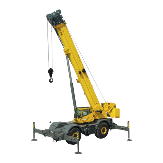
- Page 1 Grove RT Product Guide Features USt capacity ft five section, full power boom ft o settable bi fold lattice, swingaway extension ft or , m ft extension inserts Grove MEGAFORM™ boom lb counterweight hydraulically installed and removed...
- Page 2 Features Removable counterweight Counterweight and auxiliary hoist is hydraulically removed/installed for easier hauling from job to job. CraneSTAR is an exclusive and innovative crane asset management system that helps improve your profitability and reduce costs by remotely monitoring critical crane data. Visit www.cranestar.com for more information.
- Page 3 Contents Features Specifications Dimensions and weights Working range Mode A vs. Mode B Load chart Mode B Load chart fixed o settable swingaway Working range with one ft insert Working range with two ft inserts Load charts fixed o settable swingaway with inserts Load charts Mode A Lu ng extension charts...
- Page 4 Specifications Superstructure Load moment and anti two block system Boom Standard “Graphic Display” load moment and anti-two block system with audio-visual warning and control 11,4 m – 43,2 m (38 ft – 142 ft) five-section, sequenced lever lockout. These systems provide electronic display synchronized full power boom with A and B mode.
- Page 5 Specifications and service indicator. Replaceable cartridge with Superstructure continued micron filtration rating of 5/12/16. 959 L (253 gallon) hyd. reservoir. Carrier mounted oil cooler with thermostatically controlled hydraulic motor driven Hoist specifications HP fan/air to oil. System pressure test ports. main and auxiliary hoist Planetary reduction with automatic spring applied Outrigger controls...
- Page 6 Specifications Maximum speed Carrier continued 35 km/h (22 mph) Drive Gradeability theoretical 4 x 4. Steering (Based on 52 607 kg [115,976 lb] GVW, 29.5 x 25 tires, 43,2 m [142 ft] boom, plus 17,0 m [56 ft] Fully independent power steering: swingaway, 22,000 lb counterweight, 80 t [90 USt] Front: Full hydraulic steering wheel controlled.
- Page 7 Dimensions and weights Tires wheel steer wheel steer Outside turn radius Outside curb ° ° Tail Swing clearance Inside Inside turn Curb radius Radius C L Rotation Carrier bearing plate ° ° Ground line Dimensions are in mm (inches) Weights G.V.W.
- Page 8 Working range . ft main boom ft fixed offset swingaway H ft OFFSET OFFSET ' EXT. OFFSET ' EXT. Max. boom angle Axis of Rotation Operating radius in feet from axis of rotation Dimensions are for largest Grove furnished hook block and headache ball, with anti two block activated.
- Page 9 Mode A vs. Mode B Mode A – inner-mid retracted Main boom length in feet Boom sections: Percent extension Inner mid Center mid Outer mid Mode B – normal mode Main boom length in feet Boom sections: Percent extension Inner mid Center mid Outer mid THIS CHART IS ONLY A GUIDE AND SHOULD NOT BE USED TO OPERATE THE CRANE.
- Page 10 Load charts Mode B ˚ . ft . ft ft spread Pounds Main boom length in feet Feet Minimum boom angle deg for indicated length no load Maximum boom length ft at deg boom angle no load LMI operating code. Refer to LMI manual for instructions. *This capacity is based upon maximum obtainable boom angle.
- Page 11 Load charts Bi fold swingaway fixed offsettable angles ˚ . ft . ft ft spread Pounds ft LENGTH ft LENGTH OFFSET OFFSET OFFSET OFFSET OFFSET OFFSET Feet NOTES: . All capacities above the bold line are based on structural strength of boom extension and do not exceed % of tipping loads, in accordance with SAE J .
- Page 12 Working range . ft main boom and one ft insert H ft OFFSET ' EXT. OFFSET OFFSET Max. boom angle Axis of rotation Operating radius in feet from axis of rotation Dimensions are for largest Grove furnished hook block and headache ball, with anti two block activated. ' .
- Page 13 Working range . ft main boom and two ft inserts H ft OFFSET ' EXT. OFFSET OFFSET Max. boom angle Axis of rotation Operating radius in feet from axis of rotation Dimensions are for largest Grove furnished hook block and headache ball, with anti two block activated. ' .
- Page 14 Load charts Bi fold swingaway with inserts fixed angles . ft . ft ˚ inserts ft spread Pounds ft LENGTH + INSERT ft LENGTH + INSERTS ° ° ° ° ° ° OFFSET OFFSET OFFSET OFFSET OFFSET OFFSET Feet NOTES: .
- Page 15 Load charts Mode A . ft . ft ˚ ft spread Pounds Feet Minimum boom angle deg for indicated length no load Maximum boom length ft at deg boom angle no load LMI operating code. Refer to LMI manual for instructions. *This capacity is based upon maximum obtainable boom angle.
- Page 16 Load charts Mode A . ft . ft Stationary ˚ . ft . ft Pick and carry Boom centered up to . mph over front Pounds Pounds Main boom Main boom Main boom length in feet Main boom length in feet Feet Feet Minimum boom angle °...
- Page 17 ft luffing bi fold boom extension Mode B fixed offsettable angles . ft . ft ˚ ft spread Pounds ft LENGTH ft LENGTH ° ° ° ° ° ° OFFSET OFFSET OFFSET OFFSET OFFSET OFFSET Feet NOTES: . All capacities above the bold line are based on structural strength of boom extension and do not exceed % of tipping loads, in accordance...
- Page 18 ft luffing bi fold boom extension Mode B intermediate offsettable angles . ft . ft ˚ ft spread Pounds ft LENGTH ft LENGTH ° ° ° ° ° ° ° ° OFFSET OFFSET OFFSET OFFSET Feet NOTES: . All capacities above the bold line are based on structural strength of boom extension and do not exceed % of...
- Page 19 ft luffing bifold boom extension with inserts Mode B intermediate offsettable angles . ft . ft ˚ ft inserts ft spread Pounds ft LENGTH + INSERT ft LENGTH + INSERTS ° ° ° ° ° ° OFFSET OFFSET OFFSET OFFSET OFFSET OFFSET Feet NOTES: .
- Page 20 ft luffing bi fold boom extension with inserts Mode B intermediate offsettable angles . ft . ft ˚ ft inserts ft spread Pounds ft LENGTH ft + INSERT ft LENGTH ft + INSERTS ° ° ° ° ° ° ° °...
- Page 21 Load handling Weight reductions for load handling devices Folding boom extension ft extension erected ft extension erected insert erected inserts erected *Reduction of main boom capacities no deduct required for stowed boom extension Auxiliary boom nose Hookblocks and headache balls: USt, sheave lb + USt, sheave...
- Page 22 Notes...
- Page 23 Notes Grove RT...
- Page 24 Manitowoc Cranes Regional headquarters Americas Europe, Middle East, Africa China Greater Asia-Pacific Manitowoc, Wisconsin, USA Ecully, France Shanghai, China Singapore Tel: + Tel: + Tel: + Tel: + Fax: + Fax: + Fax: + Fax: + Shady Grove, Pennsylvania, USA...
Need help?
Do you have a question about the Grove RT890E and is the answer not in the manual?
Questions and answers
Where do you attach rigging to pick up a Grov RT890E to load on a ship?