Table of Contents
Advertisement
Quick Links
PZ103E
P-73x Nanopositioners
User Manual
Version: 1.0.0
Date: 10.12.2012
This document describes the following
products:
P-733, P-734
Piezo XY stage
P-733.2CD/.2CL
P-733.2DD direct drive
P-734.2CD/.2CL ultra-straight motion
P-733
Piezo XYZ stage
P-733.3CD/.3CL
P-733.3DD direct drive
P-733
Precision Z stage
P-733.ZCD/.ZCL
.2CD/.3CD/.ZCD/.2DD/.3DD with Sub-D
connector
.2CL/.3CL/.ZCL with LEMO connector
Physik Instrumente (PI) GmbH & Co. KG · Auf der Römerstr. 1 76228 Karlsruhe, Germany
Phone +49 721 4846-0 · Fax +49 721 4846-1019 · E-mail info@pi.ws
Advertisement
Table of Contents

Related Manuals for PI P-73 Series


Summary of Contents for PI P-73 Series
- Page 1 P-733 Precision Z stage P-733.ZCD/.ZCL .2CD/.3CD/.ZCD/.2DD/.3DD with Sub-D connector .2CL/.3CL/.ZCL with LEMO connector Physik Instrumente (PI) GmbH & Co. KG · Auf der Römerstr. 1 76228 Karlsruhe, Germany Phone +49 721 4846-0 · Fax +49 721 4846-1019 · E-mail info@pi.ws...
- Page 2 With regard thereto, Physik Instrumente (PI) GmbH & Co. KG retains all the rights. Use of said text, photographs and drawings is permitted only in part and only upon citation of the source.
-
Page 3: Table Of Contents
Contents About this Document Goal and Target Audience of this User Manual ........... 1 Symbols and Typographic Conventions ............... 1 Other Applicable Documents ................2 Downloading Manuals ..................3 Safety Intended Use ......................5 General Safety Instructions .................. 6 Organizational Measures ..................7 Product Description Features and Applications .................. - Page 4 Maintenance General Notes on Maintenance ................31 Cleaning the P-73x .....................31 Troubleshooting Customer Service Technical Data 10.1 Specifications......................37 10.1.1 Data Table ..................37 10.1.2 Maximum Ratings ................39 10.1.3 Ambient Conditions and Classifications ...........40 10.2 Dimensions ......................41 10.3 Torque for Stainless Steel Screws (A2-70) ............46 10.4 Pin Assignment ....................47 10.5...
-
Page 5: About This Document
1 About this Document About this Document In this Chapter Goal and Target Audience of this User Manual ............1 Symbols and Typographic Conventions ................ 1 Other Applicable Documents ..................2 Downloading Manuals ....................3 1.1 Goal and Target Audience of this User Manual This user manual contains the necessary information for the intended use of the P-73x (x stands for the different models (p. -
Page 6: Other Applicable Documents
1 About this Document INFORMATION Information for easier handling, tricks, tips, etc. Symbol/ Meaning Label Action consisting of several steps whose sequential order must be observed Action consisting of one or several steps whose sequential order is irrelevant List item p. -
Page 7: Downloading Manuals
P-5xx / P-6xx / P-7xx Piezo Positioning Systems PZ240EK Short Instructions 1.4 Downloading Manuals 1. Open the PI website http://www.pi-portal.ws. 2. Click Downloads. 3. Click the corresponding category (e. g. P Piezo Actuators, Nanopositioning & Scanning Systems). 4. Click the corresponding product code (e. g. P-733). -
Page 9: Safety
The intended use of the P-73x is only possible in combination with suitable drive and control electronics (p. 50) available from PI. The electronics is not included in the scope of delivery of the P-73x. The electronics must provide the required operating voltages. To ensure proper performance of the servo-control system, the electronics must be able to read out and process the signals from the capacitive sensors. -
Page 10: General Safety Instructions
2 Safety 2.2 General Safety Instructions The P-73x is built according to state-of-the-art technology and recognized safety standards. Improper use can result in personal injury and/or damage to the P-73x. Only use the P-73x for its intended purpose, and only use it if it is in a good working order. -
Page 11: Organizational Measures
2 Safety 2.3 Organizational Measures User manual Always keep this user manual available by the P-73x. The latest versions of the user manuals are available for download (p. 3) on our website. Add all information given by the manufacturer to the user manual, for example supplements or Technical Notes. -
Page 13: Product Description
3 Product Description Product Description In this Chapter Features and Applications ..................... 9 Model Overview ......................10 Product View ....................... 11 Scope of Delivery ......................12 Technical Features ...................... 12 3.1 Features and Applications P-73x stages are piezo-actuator-driven precision positioning systems with up to three motion axes. -
Page 14: Model Overview
3 Product Description 3.2 Model Overview The following standard versions of the P-733 and P-734 are available: 3.2.1 Piezo XY Stage Model Description P-733.2CD High-Precision XY Nanopositioning System, 100 µm × 100 µm, Capacitive Sensors, Parallel Metrology, Sub-D Connector P-733.2CL High-Precision XY Nanopositioning System, 100 µm ×... -
Page 15: Precision Z Stage
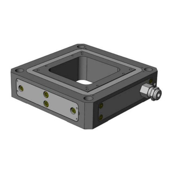
3 Product Description 3.2.3 Precision Z Stage Model Description P-733.ZCD Compact Precision Nanopositioning Vertical Stage, 100 µm, Capacitive Sensor, Sub-D Connector P-733.ZCL Compact Precision Nanopositioning Vertical Stage, 100 µm, Capacitive Sensor, LEMO Connector 3.3 Product View The illustration serves as an example and can differ from your stage model. Figure 1: Example of product view Moving platform Base body... -
Page 16: Scope Of Delivery
3 Product Description 3.4 Scope of Delivery Order Number Items P-73x Stage according to order (p. 10) 000036450 M4 screw set for protective earth, consisting of: 1 M4x8 flat-head screw with cross recess, ISO 7045 2 safety washers ... -
Page 17: Capacitive Sensors
3 Product Description 3.5.3 Capacitive Sensors The capacitive sensors of the P-73x measure the position directly at the moving platform (direct metrology) and work without contact. Neither friction nor hysteresis interferes with the measurement, which allows excellent linearity values to be achieved in combination with the high position resolution. -
Page 19: Unpacking
2. Compare the contents against the items covered by the contract and against the packing list. 3. Inspect the contents for signs of damage. If parts are missing or you notice signs of damage, contact PI immediately. 4. Keep all packaging materials in case the product needs to be returned. P-73x Nanopositioners PZ103E Version: 1.0.0... -
Page 21: Installation
Do not open the P-73x. Discharge the piezo actuators of the stage before installation: Connect the stage to the switched-off PI controller, which is equipped with an internal discharge resistor. Do not pull out the connector from the electronics during operation. - Page 22 NOTICE Unsuitable cables! Unsuitable cables can damage the electronics. Only use cables from PI for connecting the P-73x to the electronics. NOTICE Damage from incorrect mounting! Incorrect mounting of the P-73x or incorrectly mounted parts can damage the P-73x.
-
Page 23: Connecting The P-73X To A Protective Earth Conductor
5 Installation 5.2 Connecting the P-73x to a Protective Earth Conductor INFORMATION In the case of P-73x stages with Sub-D connectors, ground loops can occur when the stage is grounded via its protective earth connector as well as by the shield of the connection cable for the electronics. - Page 24 5 Installation Figure 2: Mounting of the protective earth conductor (profile view) Base body of the P-73x Flat washer Safety washer Screw Cable lug Protective earth conductor 1. If necessary, fasten a suitable cable lug to the protective earth conductor. 2.
-
Page 25: Mounting The P-73X
5 Installation 5.3 Mounting the P-73x NOTICE Warping of the P-73x due to mounting on uneven surfaces! Mounting the P-73x on an uneven surface can warp the P-73x. Warping reduces the accuracy. Mount the P-73x on an even surface. The recommended evenness of the surface is ≤20 µm. - Page 26 5 Installation Figure 3: Mounting holes in the base body Prerequisite You have read and understood the General Notes on Installation (p. 17). Tools and accessories: Screws of appropriate size and length (see "Dimensions" (p. 41)) Suitable tools Mounting the stage on a surface 1.
-
Page 27: Affixing The Load
5 Installation 5.4 Affixing the Load NOTICE Mechanical overload due to high torques! When affixing the load, high torques can damage the piezo actuators, sensors and piezo levers of the P-73x and can cause losses in accuracy. Observe the torque range (p. 46) given for the used screws when affixing the load. - Page 28 5 Installation INFORMATION The arrows in the figures (see "Dimensions" (p. 41)) show the positive direction of motion. Center of load at the optimum position: Figure 4: Example of an optimally affixed load Center of load at an unsuitable position: Figure 5: High set-up and center of load far above the moving platform Figure 6: Long lever and center of load on the side of the moving platform Version: 1.0.0...
- Page 29 5 Installation Prerequisite You have read and understood the General Notes on Installation (p. 17). Tools and accessories: Screws of appropriate size and length (see "Dimensions" (p. 41)) Suitable tools Affixing the Load Only affix loads to the threaded holes intended for this purpose (see "Dimensions"...
-
Page 31: Start-Up And Operation
6 Start-up and Operation Start-up and Operation In this Chapter General Notes on Start-Up and Operation ..............27 Operating the P-73x ....................30 Discharging the P-73x ....................30 6.1 General Notes on Start-Up and Operation CAUTION Risk of electric shock if the protective earth conductor is not connected! If a protective earth conductor is not or not properly connected, dangerous touch voltages can occur and there is a risk of electric shock. - Page 32 Operating voltages that are too high or incorrectly connected can cause damage to the P-73x. Only operate the P-73x with controllers/drivers and original accessories from PI. Do not exceed the operating voltage range (p. 39) for which the P-73x is specified.
- Page 33 6 Start-up and Operation INFORMATION Systems are calibrated at the factory to achieve optimum performance. Replacing the system components will cause a loss in performance when stages are used, whose ID chip (p. 13) does not contain any calibration data, or when analog controllers are used.
-
Page 34: Operating The P-73X
2. Set the piezo voltage to 0 V on the controller. In open-loop operation: Set the piezo voltage to 0 V on the controller. Discharging a P-73x that is not connected to the controller Connect the stage to the switched-off controller from PI. Version: 1.0.0 PZ103E P-73x Nanopositioners... -
Page 35: Maintenance
7 Maintenance Maintenance In this Chapter General Notes on Maintenance ................... 31 Cleaning the P-73x ...................... 31 7.1 General Notes on Maintenance NOTICE Misalignment from loosening screws! The P-73x is maintenance-free and achieves its positioning accuracy as a result of the optimum alignment of mechanical components and piezo actuators. -
Page 37: Troubleshooting
8 Troubleshooting Troubleshooting Problem Possible Causes Solution Check the cable connections. No or limited motion The cable is not connected correctly Do not exceed the permissible Excessive load compressive/tensile stress capacity according to the specifications (p. 37). After changing the load to be moved, The load was changed perform a zero-point adjustment... - Page 38 8 Troubleshooting Problem Possible Causes Solution P-73x or controller When stages, whose ID chip (p. 13) has been replaced does not contain any calibration data, or analog controllers are used, the axis displacement has to be recalibrated after the P-73x or the controller has been replaced.
-
Page 39: Customer Service
9 Customer Service Customer Service For inquiries and orders, contact your PI sales engineer or send us an e-mail (info@pi.ws). If you have questions concerning your system, have the following information ready: Product codes and serial numbers of all products in the system ... -
Page 41: Technical Data
10 Technical Data 10 Technical Data In this Chapter Specifications ......................37 Dimensions ........................41 Torque for Stainless Steel Screws (A2-70) ..............46 Pin Assignment ......................47 Suitable Piezo Controllers ................... 50 10.1 Specifications 10.1.1 Data Table Unit P-733.2CD P-733.3CD P-733.2DD P-733.3DD P-734.2CD... - Page 42 10 Technical Data Unit P-733.2CD P-733.3CD P-733.2DD P-733.3DD P-734.2CD P-733.ZCD P-733.2CL P-733.3CL P-734.2CL P-733.ZCL Repeat- – < 1 – <1 – <2 ability in Z Pitch in X, Y µrad <5 <5 <5 <5 <3 – Tilt around X, Y (with µrad –...
-
Page 43: Maximum Ratings
10 Technical Data Unit P-733.2CD P-733.3CD P-733.2DD P-733.3DD P-734.2CD P-733.ZCD P-733.2CL P-733.3CL P-734.2CL P-733.ZCL Material Aluminum Aluminum Aluminum Aluminum Aluminum Aluminum Dimensions 100 mm × 100 mm × 100 mm × 100 mm × 130 mm × 100 mm × 100 mm ×... -
Page 44: Ambient Conditions And Classifications
10 Technical Data Stage Maximum Maximum Operating Maximum Power Operating Voltage Frequency (Unloaded) Consumption P-733.3CD –20 to +120 V 153 Hz (in X and Y) 18 W (in X and Y) P-733.3CL 467 Hz (in Z) 24 W (in Z) P-733.3DD –20 to +120 V 400 Hz (in X and Y) -
Page 45: Dimensions
10 Technical Data 10.2 Dimensions Dimensions in mm. Note that the decimal places are separated by a comma in the drawings. Standard tolerance according to DIN ISO 2768 - f - H Roughness Ra 1.6 Figure 7: P-733.2Cx P-73x Nanopositioners PZ103E Version: 1.0.0... - Page 46 10 Technical Data Figure 8: P-733.2DD Version: 1.0.0 PZ103E P-73x Nanopositioners...
- Page 47 10 Technical Data Figure 9: P-733.3Cx P-73x Nanopositioners PZ103E Version: 1.0.0...
- Page 48 10 Technical Data Figure 10: P-733.3DD Version: 1.0.0 PZ103E P-73x Nanopositioners...
- Page 49 10 Technical Data Figure 11: P-733.ZCx P-73x Nanopositioners PZ103E Version: 1.0.0...
-
Page 50: Torque For Stainless Steel Screws (A2-70)
10 Technical Data Figure 12: P-734.2Cx 10.3 Torque for Stainless Steel Screws (A2-70) Screw Size Minimum Torque Maximum Torque 1.5 Nm 2.5 Nm 0.8 Nm 1.1 Nm M2.5 0.3 Nm 0.4 Nm 0.15 Nm 0.2 Nm M1.6 0.06 Nm 0.12 Nm Version: 1.0.0 PZ103E P-73x Nanopositioners... -
Page 51: Pin Assignment
10 Technical Data 10.4 Pin Assignment Sub-D mix connector 7W2 Only for P-733.ZCD: Figure 13: Sub-D mix connector 7W2: Front side with connections Signal Function A1 inner Input Piezo voltage + conductor A2 inner Output Probe sensor signal conductor (nonmoving part of the capacitive sensor) A2 outer Shield conductor... - Page 52 10 Technical Data Sub-D mix connector 25W3 Only for P-73x.2CD/.2DD/.3CD/.3DD: Figure 14: Sub-D mix connector 25W3: Front side with connections Signal Function A1 inner Output Probe sensor signal, channel 2 conductor (nonmoving part of the capacitive sensor) A1 outer Shield of Probe sensor signal, channel 2 conductor A2 inner Output...
- Page 53 10 Technical Data Signal Function Input Piezo voltage +, channel 1 Input Target sensor signal, channel 1 (movable part of the capacitive sensor) Shield of Target sensor signal, channel 2 Shield of Target sensor signal, channel 3 Free – Free –...
-
Page 54: Suitable Piezo Controllers
10 Technical Data LEMO coaxial connector Only for P-73x.2CL/.3CL/.ZCL (one PZT, P and T connector each per axis): Figure 15: LEMO coaxial connectors Connector Signal Function Connector Shell Output Probe sensor signal (nonmoving part Cable shield of the capacitive sensor) Input Target sensor signal (movable part of Cable shield... - Page 55 10 Technical Data Controller E-500 modular piezo controller with – – – – – E-509.C1A control module for capacitive sensors and E-505 1-channel amplifier Optional: E-517 interface and display module E-500 modular piezo controller with – – – – E-509.C3A control module for capacitive sensors and E-503 3-channel amplifier Optional: E-517 interface and display...
-
Page 57: Old Equipment Disposal
Instrumente (PI) GmbH & Co. KG ensures environmentally correct disposal of old PI equipment that was first put into circulation after 13 August 2005, free of charge. If you have old PI equipment, you can send it postage-free to the following address: Physik Instrumente (PI) GmbH & Co. KG Auf der Römerstr. - Page 59 12 EC Declaration of Conformity 12 EC Declaration of Conformity P-73x Nanopositioners PZ103E Version: 1.0.0...
Need help?
Do you have a question about the P-73 Series and is the answer not in the manual?
Questions and answers