Table of Contents
Advertisement
Quick Links
PZ258E
P763 Nanopositioner
User Manual
Version: 1.1.0
Physik Instrumente (PI) GmbH & Co. KG, Auf der Roemerstrasse 1, 76228 Karlsruhe, Germany
Phone +49 721 4846-0, Fax +49 721 4846-1019, Email info@pi.ws, www.pi.ws
Date: 17.06.2020
This document describes the following product:
P763.22C
Compact XY nanopositioner with clear
aperture, 200 µm × 200 µm, direct position
measuring, capacitive sensors
Advertisement
Table of Contents

Related Manuals for PI P-763 Series


Summary of Contents for PI P-763 Series
- Page 1 Compact XY nanopositioner with clear aperture, 200 µm × 200 µm, direct position measuring, capacitive sensors Physik Instrumente (PI) GmbH & Co. KG, Auf der Roemerstrasse 1, 76228 Karlsruhe, Germany Phone +49 721 4846-0, Fax +49 721 4846-1019, Email info@pi.ws, www.pi.ws...
- Page 2 The patents held by PI are found in our patent list: https://www.physikinstrumente.com/en/about-pi/patents © 2020 Physik Instrumente (PI) GmbH & Co. KG, Karlsruhe, Germany. The text, photographs and drawings in this manual are protected by copyright. With regard thereto, Physik Instrumente (PI) GmbH & Co. KG retains all the rights.
-
Page 3: Table Of Contents
Contents About this Document Objective and Target Audience of this User Manual ..........1 Symbols and Typographic Conventions ..............1 Figures ........................2 Other Applicable Documents ..................2 Downloading Manuals ....................3 Safety Intended Use ......................5 General Safety Instructions ..................5 Organizational Measures .................... - Page 4 Maintenance General Notes on Maintenance ................27 Cleaning the P-763 ....................27 Troubleshooting Customer Service Technical Data 10.1 Specifications ......................33 10.1.1 Data Table ....................33 10.1.2 Maximum Ratings ..................34 10.2 Ambient Conditions and Classifications ..............34 10.3 Dimensions ....................... 35 10.4 Torque for Stainless Steel Screws (A2-70) ..............
-
Page 5: About This Document
1 About this Document About this Document In this Chapter Objective and Target Audience of this User Manual ..............1 Symbols and Typographic Conventions ..................1 Figures ............................2 Other Applicable Documents ......................2 Downloading Manuals ........................3 Objective and Target Audience of this User Manual This manual contains the information required for using the P-763 as intended. -
Page 6: Figures
Other Applicable Documents The devices and software tools from PI mentioned in this documentation are described in separate manuals. The latest versions of the user manuals are available for download (p. 3) on our website. -
Page 7: Downloading Manuals
If a manual is missing or problems occur with downloading: Contact our customer service department (p. 31). Downloading manuals 1. Open the website www.pi.ws. 2. Search the website for the product number (e.g., P-763) or the product family (e.g., Nanopositioner). -
Page 9: Safety
The P-763 can only be used as intended in conjunction with suitable electronics (p. 11) available from PI. The electronics are not included in the P-763's scope of delivery. The electronics must provide the required operating voltages. To ensure proper performance of the servo control system, the electronics must also be able to read out and process the signals from the position sensors. - Page 10 Do not open the P-763. Discharge the P-763's piezo actuators before installing: Connect the P-763 to the switched-off electronics from PI equipped with an internal discharge resistor. Do not pull the connectors out of the electronics during operation.
-
Page 11: Organizational Measures
2 Safety Organizational Measures User manual Always keep this user manual together with the P-763. The latest versions of the user manuals are available for download (p. 3) on our website. Add all information from the manufacturer to the user manual, for example supplements or technical notes. -
Page 13: Product Description
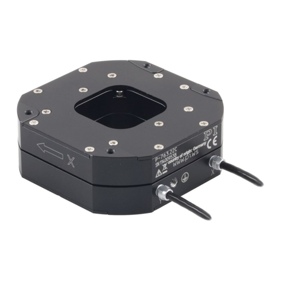
3 Product Description Product Description In this Chapter Product View ..........................9 Product Labeling .......................... 10 Scope of Delivery ......................... 11 Suitable Electronics ........................11 Required Accessories ........................11 Technical Features ........................12 Product View The figure serves as an example and can differ from your positioner model. Figure 1: Exemplary product view of the P-763 Base body... -
Page 14: Product Labeling
Warning sign "Pay attention to the manual!" Old equipment disposal (p. 39) Country of origin: Germany Country of origin WWW.PI.WS Manufacturer's address (website) CE conformity mark Symbol for the protective earth conductor, marks the protective earth connection of the P-763 (p. 16) -
Page 15: Scope Of Delivery
3 Product Description Scope of Delivery Product number Description P-763.22C Compact XY nanopositioner with clear aperture, 200 µm × 200 µm, direct position measuring, capacitive sensors 000036450 M4 screw set for protective earth, consisting of: One flat-head screw with cross recess, M4x8, ISO 7045 ... -
Page 16: Technical Features
3 Product Description Technical Features 3.6.1 PICMA® Piezo Actuators P-763 positioners are driven by PICMA® piezo actuators. PICMA® actuators have all-ceramic insulation and their performance and lifetime are therefore far superior to conventional actuators. The ceramic insulation layer protects the monolithic piezoceramic block against humidity and failure due to increased leakage current. -
Page 17: Unpacking
4 Unpacking Unpacking NOTICE Mechanical overload due to incorrect handling! An impermissible mechanical load on the platform of the P-763 can cause damage to the piezo actuators, sensors, and flexures of the P-763 as well as loss of accuracy. Do not touch any sensitive parts (e.g., platform) when handling the P-763. 1. -
Page 19: Installation
Do not open the P-763. Discharge the P-763's piezo actuators before installing: Connect the P-763 to the switched-off electronics from PI equipped with an internal discharge resistor. Do not pull the connectors out of the electronics during operation. -
Page 20: Connecting The P-763 To The Protective Earth Conductor
NOTICE Damage due to unsuitable cables! Unsuitable cables can damage the P-763 and the electronics. Use cables provided by PI only to connect the P-763 to the electronics. NOTICE Damage due to improper mounting! Improper mounting of the P-763 or incorrectly mounted parts can damage the P-763. - Page 21 5 Installation The P-763 has an M4 hole for attaching the protective earth conductor. This hole is marked with the symbol for the protective earth conductor . Refer to "Dimensions" (p. 35) for the exact position of the hole. Requirements ...
-
Page 22: Mounting The P-763
5 Installation Mounting the P763 NOTICE Warping of the P763 when mounted on uneven surfaces! The P-763 could warp if mounted on an uneven surface. Warping reduces the accuracy. Mount the P-763 onto an even surface. The recommended flatness of the surface is ≤20 µm. -
Page 23: Fixing The Load
5 Installation Tools and accessories You have provided a suitable surface (for the required position and depth of the holes for accommodating the screws, refer to "Dimensions" (p. 35)): Four through-holes for M3 screws are provided. − − The surface flatness is ≤20 µm. −... - Page 24 5 Installation NOTICE Warping of the P763 when fixing loads with an uneven contact surface! Fixing loads with an uneven contact surface could warp the P-763. Warping reduces the accuracy. Only fix loads on the P-763 whose contact surface with the platform of the P-763 has a flatness of at least 20 μm.
- Page 25 5 Installation Center of load at an unsuitable position: Figure 6: Tall load and center of load too far above the platform Figure 7: Unwanted lever effect and center of load on the side of the platform Requirements You have read and understood the general notes on installation (p. 15). ...
-
Page 27: Startup And Operation
6 Startup and Operation Startup and Operation In this Chapter General Notes on Startup and Operation ..................23 Operating the P-763 ........................24 Discharging the P-763 ........................25 General Notes on Startup and Operation CAUTION Risk of electric shock if the protective earth conductor is not connected! If a protective earth conductor is not or not properly connected, dangerous touch voltages can occur on the P-763 in the case of malfunction or failure of the system. -
Page 28: Operating The P-763
Operating voltages that are too high or incorrectly connected can cause damage to the P-763. Operate the P-763 only with controllers/drivers and original accessories from PI. Do not exceed the operating voltage range (p. 34) for which the P-763 is specified. -
Page 29: Discharging The P-763
Before demounting (e.g., before cleaning and transporting the P-763 and for modifications) The P-763 is discharged via the discharge resistor inside the electronics from PI. Discharging a positioner connected to the electronics In closed-loop operation: 1. Switch off the servo mode on the controller. -
Page 31: Maintenance
7 Maintenance Maintenance In this Chapter General Notes on Maintenance ....................27 Cleaning the P-763 ........................27 General Notes on Maintenance NOTICE Misalignment due to loosening screws! The P-763 is maintenance-free and achieves its positioning accuracy as a result of the optimal alignment of mechanical components and piezo actuators. -
Page 33: Troubleshooting
8 Troubleshooting Troubleshooting Problem Possible causes Solution No or limited Cable not connected Check the cable connections. motion correctly Excessive load Do not exceed the maximum permissible stress and load capacities according to the specifications (p. 33). Zero shift of the sensor for ... - Page 34 8 Troubleshooting Problem Possible causes Solution The positioner Servo control parameters 1. Switch off the servo mode of the starts oscillating incorrectly set because for corresponding motion axes immediately. or positions example, the load was 2. Check the settings of the servo control inaccurately changed parameters on the controller.
-
Page 35: Customer Service
9 Customer Service Customer Service For inquiries and orders, contact your PI sales engineer or send us an email (service@pi.de). If you have any questions concerning your system, provide the following information: − Product and serial numbers of all products in the system Firmware version of the controller (if applicable) −... -
Page 37: Technical Data
10 Technical Data Technical Data In this Chapter Specifications ..........................33 Ambient Conditions and Classifications ..................34 Dimensions ..........................35 Torque for Stainless Steel Screws (A2-70) ................... 36 Pin Assignment ..........................36 10.1 Specifications 10.1.1 Data Table P763.22C Unit Tolerance Active axes X, Y Motion and positioning... -
Page 38: Maximum Ratings
10 Technical Data 10.1.2 Maximum Ratings P-763 positioners are designed for the following operating data in continuous operation: Maximum operating voltage Maximum operating Maximum power frequency (without load) consumption -20 to +120 V 100 Hz (in X) 37.6 W (18.8 W per axis) 83 Hz (in Y) To ensure stable operation, the maximum operating frequency has been defined as around one third of the mechanical resonant frequency. -
Page 39: Dimensions
10 Technical Data 10.3 Dimensions Dimensions in mm. Figure 8: P-763.22C P763 Nanopositioner PZ258E Version: 1.1.0... -
Page 40: Torque For Stainless Steel Screws (A2-70)
10 Technical Data 10.4 Torque for Stainless Steel Screws (A270) Screw size Minimum torque Maximum torque 4 Nm 6 Nm 2.5 Nm 3.5 Nm 1.5 Nm 2.5 Nm 0.8 Nm 1.1 Nm M2.5 0.3 Nm 0.4 Nm 0.15 Nm 0.2 Nm M1.6 0.06 Nm 0.12 Nm... - Page 41 10 Technical Data Signal Function Piezo voltage Probe Probe sensor signal (immovable part of the capacitive sensor) Data ID chip Data line for ID chip GND Target and ID chip Target and ID chip ground GND PZT Piezo voltage ground (not connected) Target sensor signal (movable part of the Target...
-
Page 43: Old Equipment Disposal
Dispose of your old equipment according to international, national, and local rules and regulations. In order to fulfil its responsibility as the product manufacturer, Physik Instrumente (PI) GmbH & Co. KG undertakes environmentally correct disposal of all old PI equipment made available on the market after 13 August 2005 without charge. - Page 45 12 EU Declaration of Conformity EU Declaration of Conformity For the P-763, an EU Declaration of Conformity has been issued in accordance with the following European directives: Low Voltage Directive EMC Directive RoHS Directive The applied standards certifying the conformity are listed below. Safety (Low Voltage Directive): EN 61010-1 EMC: EN 61326-1 RoHS: EN 50581 or EN IEC 63000...
Need help?
Do you have a question about the P-763 Series and is the answer not in the manual?
Questions and answers