Table of Contents
Advertisement
Quick Links
PZ251E
P-587 Positioner
User Manual
Version: 1.1.0
Physik Instrumente (PI) GmbH & Co. KG, Auf der Roemerstrasse 1, 76228 Karlsruhe, Germany
Phone +49 721 4846-0, Fax +49 721 4846-1019, Email info@pi.ws, www.pi.ws
Date: 22.04.2022
This document describes the following product:
P-587.6CD
6-axis nanopositioner with long travel range,
800 µm × 800 µm × 200 µm, ±0.5 mrad, parallel
metrology, capacitive sensors, D-sub 25W3
panel plugs
Advertisement
Table of Contents

Related Manuals for PI P-587.6CD


Summary of Contents for PI P-587.6CD
- Page 1 800 µm × 800 µm × 200 µm, ±0.5 mrad, parallel metrology, capacitive sensors, D-sub 25W3 panel plugs Physik Instrumente (PI) GmbH & Co. KG, Auf der Roemerstrasse 1, 76228 Karlsruhe, Germany Phone +49 721 4846-0, Fax +49 721 4846-1019, Email info@pi.ws, www.pi.ws...
- Page 2 The patents held by PI are found in our patent list: https://www.physikinstrumente.com/en/about-pi/patents © 2022 Physik Instrumente (PI) GmbH & Co. KG, Karlsruhe, Germany. The text, photographs and drawings in this manual are protected by copyright. With regard thereto, Physik Instrumente (PI) GmbH & Co. KG retains all the rights.
-
Page 3: Table Of Contents
Contents About this Document Objective and Target Audience of this User Manual..........1 Symbols and Typographic Conventions..............1 Figures ........................2 Other Applicable Documents ..................2 Downloading Manuals ....................3 Safety Intended Use ......................5 General Safety Instructions ..................5 Organizational Measures .................... - Page 4 Maintenance General Notes on Maintenance ................27 Cleaning the P-587 ....................27 Troubleshooting Customer Service Technical Data 10.1 Specifications ......................33 10.1.1 Data Table ....................33 10.1.2 Maximum Ratings ..................35 10.2 Ambient Conditions and Classifications ..............35 10.3 Dimensions ....................... 36 10.4 Torque for Stainless Steel Screws (A2-70) ..............
-
Page 5: About This Document
1 About this Document About this Document In this Chapter Objective and Target Audience of this User Manual ..............1 Symbols and Typographic Conventions ..................1 Figures ............................2 Other Applicable Documents ......................2 Downloading Manuals ........................3 Objective and Target Audience of this User Manual This manual contains the information required for using the P-587 as intended. -
Page 6: Figures
Other Applicable Documents The devices and software tools from PI mentioned in this documentation are described in separate manuals. The latest versions of the user manuals are available for download (p. 3) on our website. -
Page 7: Downloading Manuals
If a manual is missing or problems occur with downloading: Contact our customer service department (p. 31). Downloading Manuals 1. Open the website www.pi.ws. 2. Search the website for the product number (e.g., P-587) or the product family (e.g., nanopositioner). -
Page 9: Safety
The P-587 can only be used as intended in conjunction with suitable electronics (p. 11) available from PI. The electronics are not included in the scope of delivery of the P-587. The electronics must provide the required operating voltages. To ensure proper performance of the servo control system, the electronics must be able to read out and process the signals from the capacitive sensors. - Page 10 Do not open the P-587. Discharge the positioner's piezo actuators before installing: Connect the positioner to the switched-off PI electronics equipped with an internal discharge resistor. Do not pull out the connecting cables while the positioner or the electronics are in operation.
-
Page 11: Organizational Measures
2 Safety Organizational Measures User manual Always keep this user manual together with the P-587. The latest versions of the user manuals are available for download (p. 3) on our website. Add all information from the manufacturer to the user manual, for example supplements or technical notes. -
Page 13: Product Description
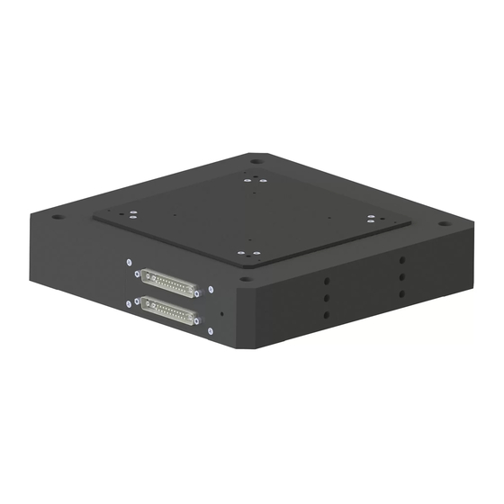
3 Product Description Product Description In this Chapter Product View ..........................9 Product Labeling .......................... 10 Scope of Delivery ......................... 10 Suitable Electronics ........................11 Technical Features ........................11 Product View The figure serves as an example and can differ from your positioner model. Figure 1: Example of product view Motion platform... -
Page 14: Product Labeling
3 Product Description Product Labeling The P-587 is labeled on the side with the connectors as follows: Labeling Description P-587.6CD Product name (example), the characters following the period refer to the model 123456789 Serial number (example), individual for each P-587... -
Page 15: Suitable Electronics
3 Product Description Suitable Electronics Product number Description E-712.6CD Modular digital piezo controller, 6 axes, capacitive sensors, TCP/IP, USB, RS-232, SPI interfaces for communication. consisting of: 1 × E-712.M1 Digital processor and interface module, TCP/IP, USB, RS-232, SPI 2 × E-711.SC3H Module for capacitive sensors, 3 channels 2 ×... -
Page 16: Id Chip
3 Product Description 3.5.4 ID Chip An ID chip is in the D-sub connector of the P-587. When the P-587 is calibrated at the factory with digital electronics, the calibration data is saved on the ID chip together with specific product information. -
Page 17: Unpacking
4 Unpacking Unpacking NOTICE Mechanical overload due to incorrect handling! An impermissible mechanical load on the motion platform of the P-587 can cause damage to the piezo actuators, sensors, and flexures of the P-587 as well as loss of accuracy. ... -
Page 19: Installation
Do not open the P-587. Discharge the positioner's piezo actuators before installing: Connect the positioner to the switched-off PI electronics equipped with an internal discharge resistor. Do not pull out the connecting cables while the positioner or the electronics are in operation. -
Page 20: Connecting The P-587 To The Protective Earth Conductor
NOTICE Damage due to unsuitable cables! Unsuitable cables can damage the P-587 and the electronics. Use cables provided by PI only to connect the P-587 to the electronics. NOTICE Damage due to improper mounting! Improper mounting of the P-587 or incorrectly mounted parts can damage the P-587. - Page 21 5 Installation INFORMATION In the case of P-587 positioners with D-sub connectors, ground loops can occur when the positioner is grounded via its protective earth connector as well as via the connecting cable's shielding for the electronics. If a ground loop occurs, contact our customer service department (p. 31). The P-587 has an M4 hole for connecting the protective earth conductor.
-
Page 22: Mounting The P-587
5 Installation Mounting the P-587 NOTICE Warping the P-587 when mounting onto uneven surfaces! The P-587 could warp if mounted on an uneven surface. Warping reduces the accuracy. Mount the P-587 onto a flat surface. The recommended flatness of the surface is ≤20 µm. ... -
Page 23: Fixing The Load
5 Installation Tools and accessories Four screws of suitable size and length (p. 36) Suitable screwdriver Mounting the P-587 1. Align the P-587 on the surface so that the corresponding holes in the P-587 and surface are in line. 2. - Page 24 5 Installation NOTICE Center of load at unsuitable position! If the center of load is located too far away from the center of the motion platform (e.g., tall load and unwanted lever effect), the P-587 can be damaged, especially in dynamic operation, by high strain on the flexure guides, high torques, and oscillations.
- Page 25 5 Installation Figure 6: Unwanted lever effect and center of load on the side of the platform Figure 7: Mounting holes in the motion platform Requirements You have read and understood the general notes on installing (p. 15). The P-587 is not connected to the electronics. Tools and accessories Screws of suitable size and length (p.
-
Page 26: Connecting The P-587 To The Electronics
5 Installation Connecting the P-587 to the Electronics INFORMATION When connecting, pay attention to the assignment specified on the labeling of the sockets, plug connectors, and cables. Requirements You have read and understood the general notes on installing (p. 15). ... -
Page 27: Starting And Operating
6 Starting and Operating Starting and Operating In this Chapter General Notes on Starting and Operating ................... 23 Operating the P-587 ........................25 Discharging the P-587 ........................25 General Notes on Starting and Operating CAUTION Risk of electric shock if the protective earth conductor is not connected! If a protective earth conductor is not or not properly connected, dangerous touch voltages can occur on the P-587 in the case of malfunction or failure of the system. - Page 28 Operating voltages that are too high or incorrectly connected can cause damage to the P-587. Operate the P-587 only with controllers/drivers and original accessories from PI. Do not exceed the operating voltage range (p. 35) specified for the P-587.
-
Page 29: Operating The P-587
Before demounting (e.g., before cleaning and transporting the P-587 and for modifications) The P-587 is discharged via the discharge resistor inside the electronics from PI. Discharging a positioner connected to the electronics In closed-loop operation: 1. Switch off the servo mode on the controller. -
Page 31: Maintenance
7 Maintenance Maintenance In this Chapter General Notes on Maintenance ....................27 Cleaning the P-587 ........................27 General Notes on Maintenance NOTICE Misalignment due to loosening screws! The P-587 is maintenance-free and achieves its positioning accuracy as a result of the optimal alignment of mechanical components and piezo actuators. - Page 32 7 Maintenance Requirements You have discharged the piezo actuators of the P-587 (p. 25). You have disconnected the P-587 from the electronics. Cleaning the P-587 Clean the surfaces of the P-587 with a cloth dampened with a mild cleanser or disinfectant (e.g., isopropyl alcohol).
-
Page 33: Troubleshooting
8 Troubleshooting Troubleshooting Problem Possible causes Solution No or limited Cable not connected Check the cable connections. motion correctly Excessive load Do not exceed the maximum permissible stress and load capacities according to the specifications (p. 33). Zero shift of the sensor for ... -
Page 35: Customer Service
9 Customer Service Customer Service For inquiries and orders, contact your PI sales engineer or send us an email (service@pi.de). If you have any questions concerning your system, provide the following information: − Product and serial numbers of all products in the system −... -
Page 37: Technical Data
10 Technical Data Technical Data Subject to change. You can find the latest product specifications on the product web page at www.pi.ws (https://www.pi.ws). In this Chapter Specifications ..........................33 Ambient Conditions and Classifications ..................35 Dimensions ..........................36 Torque for Stainless Steel Screws (A2-70) ................... 36 Pin Assignment .......................... - Page 38 The resolution of the system is limited only by the noise of the amplifier and the measuring technology because PI piezo nanopositioning systems are free of friction. All specifications based on room temperature (22 °C ±3 °C).
-
Page 39: Maximum Ratings
10 Technical Data 10.1.2 Maximum Ratings The P-587 is designed for the following operating data: Maximum operating voltage Maximum operating Maximum power frequency (unloaded) consumption -20 to +120 V X axis: 23 Hz X1, X2, Y1, Y2: Y axis: 23 Hz 40 W each Z axis: 44 Hz Z1, Z2, Z3, Z4:... -
Page 40: Dimensions
10 Technical Data 10.3 Dimensions Figure 8: P-587.6CD, dimensions in mm. Note that the decimal points are separated by a comma in the drawings. 1: Rotation center, depending on Z 10.4 Torque for Stainless Steel Screws (A2-70) Screw size Minimum torque... -
Page 41: Pin Assignment
10 Technical Data 10.5 Pin Assignment D-sub 25W3 panel plug: XY ROT Figure 9: D-sub 25W3 connector (m): Front with connections Signal Function A1 inner conductor Output Probe sensor signal, Y1 (immovable part of the capacitive sensor) A1 outer conductor Shielding for Probe sensor signal, Y1 A2 inner conductor Output... - Page 42 10 Technical Data Signal Function Free Input Piezo voltage -, Y1 and Y2 Free Input Piezo voltage -, X1 and X2 Shielding for Target sensor signal, X D-sub 25W3 panel plug: Z TIP TILT Figure 10: D-sub 25W3 connector (m): Front with connections Signal Function Probe sensor signal, Z2...
- Page 43 10 Technical Data Signal Function Target sensor signal, Z1 Input (movable part of the capacitive sensor) Shielding for Target sensor signal, Z2 Shielding for Target sensor signal, Z3 Free Free Free Free Free Input Piezo voltage -, Z3 and Z4 Free Input Piezo voltage -, Z1 and Z2...
-
Page 45: Old Equipment Disposal
Dispose of your old equipment according to international, national, and local rules and regulations. In order to fulfill its responsibility as the product manufacturer, Physik Instrumente (PI) GmbH & Co. KG undertakes environmentally correct disposal of all old PI equipment made available on the market after 13 August 2005 without charge. - Page 47 12 European Declarations of Conformity European Declarations of Conformity For the P-587, declarations of conformity were issued according to the following European statutory requirements: Low Voltage Directive EMC Directive RoHS Directive The standards applied for certifying conformity are listed below. Safety (Low Voltage Directive): EN 61010-1 EMC: EN 61326-1 RoHS: EN IEC 63000...
Need help?
Do you have a question about the P-587.6CD and is the answer not in the manual?
Questions and answers