Table of Contents
Advertisement
Quick Links
PZ234E
P-62x Positioning Systems
User Manual
Version: 1.1.0
Physik Instrumente (PI) GmbH & Co. KG, Auf der Roemerstrasse 1, 76228 Karlsruhe, Germany
Phone +49 721 4846-0, Fax +49 721 4846-1019, Email info@pi.ws, www.pi.ws
Date: 27.08.2018
This document describes the following products:
P-620, P-621, P-622, P-625, P-628, P-629
PIHera piezo linear stage
P-620.1CD/.1CL/.10L
P-621.1CD/.1CL/.10L/.1U
P-622.1CD/.1CL/.10L/.1U
P-625.1CD/.1CL/.10L
P-628.1CD/.1CL/.10L
P-629.1CD/.1CL/.10L
P-620, P-621, P-622, P-625, P-628, P-629
PIHera piezo XY stage
P-620.2CD/.2CL/.20L
P-621.2CD/.2CL/.20L/.2U
P-622.2CD/.2CL/.20L/.2U
P-625.2CD/.2CL/.20L
P-628.2CD/.2CL/.20L
P-629.2CD/.2CL/.20L
P-620, P-621, P-622
PIHera precision Z stage
P-620.ZCD/.ZCL/.Z0L
P-621.ZCD/.ZCL/.Z0L
P-622.ZCD/.ZCL/.Z0L
.1CD/.2CD/.ZCD
= with Sub-D connector 7W2
.1U/.2U
= with Sub-D connector 5W1 (f)
.1CL/.2CL/.ZCL/.10L/.20L/.Z0L
= with LEMO connector
Advertisement
Table of Contents

Related Manuals for PI P-62 Series


Summary of Contents for PI P-62 Series
- Page 1 = with Sub-D connector 7W2 .1U/.2U = with Sub-D connector 5W1 (f) .1CL/.2CL/.ZCL/.10L/.20L/.Z0L = with LEMO connector Physik Instrumente (PI) GmbH & Co. KG, Auf der Roemerstrasse 1, 76228 Karlsruhe, Germany Phone +49 721 4846-0, Fax +49 721 4846-1019, Email info@pi.ws, www.pi.ws...
- Page 2 The patents held by PI are found in our patent list: http://www.physikinstrumente.com/en/about-pi/patents © 2018 Physik Instrumente (PI) GmbH & Co. KG, Karlsruhe, Germany. The text, photographs and drawings in this manual are protected by copyright. With regard thereto, Physik Instrumente (PI) GmbH & Co. KG retains all the rights.
-
Page 3: Table Of Contents
Contents About this Document Objective and Target Audience of this User Manual..........1 Symbols and Typographic Conventions..............1 Definition of Terms ..................... 2 Figures ........................2 Other Applicable Documents ..................3 Downloading Manuals ....................3 Safety Intended Use ......................5 General Safety Instructions .................. - Page 4 Maintenance General Notes on Maintenance ................35 Cleaning the P-62x ....................35 Troubleshooting Customer Service Technical Data 10.1 Specifications ......................41 10.1.1 Data Table ....................41 10.1.2 Materials Used for Vacuum-Compatible Models ........45 10.1.3 Maximum Ratings ..................45 10.1.4 Ambient Conditions and Classifications ............46 10.2 Dimensions .......................
-
Page 5: About This Document
1 About this Document About this Document In this Chapter Objective and Target Audience of this User Manual ..............1 Symbols and Typographic Conventions ..................1 Definition of Terms ........................2 Figures ............................2 Other Applicable Documents ......................3 Downloading Manuals ........................3 Objective and Target Audience of this User Manual This user manual contains the necessary information for the intended use of the P-62x (x stands for the different models (p. -
Page 6: Definition Of Terms
1 About this Document Symbol/Label Meaning Action consisting of several steps whose sequential order must be observed Action consisting of one or several steps whose sequential order is irrelevant List item p. 5 Cross-reference to page 5 RS-232 Labeling of an operating element on the product (example: socket of the RS-232 interface) Warning signs affixed to the product that refer to detailed... -
Page 7: Other Applicable Documents
1 About this Document Other Applicable Documents The devices and software tools from PI mentioned in this documentation are described in their own manuals. Product Document E-503 piezo amplifier module PZ62E user manual E-505 piezo amplifier module E-610 piezo amplifier / servo controller (OEM... - Page 8 Click the links in the browser window to change to the content for your product and log in using the access data that you received. General procedure: 1. Open the website www.pi.ws. 2. If access to the manuals is protected by a password: a) Click Login.
-
Page 9: Safety
The intended use of the P-62x is only possible in combination with suitable electronics (p. 15) that is available from PI. The electronics is not included in the scope of delivery of the P-62x. The electronics must provide the required operating voltages. To ensure proper performance of the servo control system, the electronics must be able to read out and process the signals from the capacitive sensors. - Page 10 Do not open the P-62x. Discharge the positioner's piezo actuators before installation: Connect the positioner to the switched-off PI controller, which is equipped with an internal discharge resistor. Do not pull the plug connector out of the electronics during operation.
-
Page 11: Organizational Measures
2 Safety Organizational Measures User manual Always keep this user manual available with the P-62x. The latest versions of the user manuals are available for download (p. 3) on our website. Add all information from the manufacturer to the user manual, for example supplements or technical notes. -
Page 13: Product Description
3 Product Description Product Description In this Chapter Model Overview ..........................9 Product View ..........................12 Product Labeling .......................... 13 Scope of Delivery ......................... 14 Suitable Electronics ........................15 Accessories ........................... 15 Technical Features ........................16 Model Overview The P-62x is available in the following versions: PIHera piezo linear stage Model Description... - Page 14 3 Product Description Model Description P-625.10L PIHera precision linear nanopositioning system, 600 µm, without sensor, LEMO connector(s) P-628.1CD PIHera precision linear nanopositioning system, 800 µm, direct position measuring, capacitive sensor, Sub-D connector P-628.1CL PIHera precision linear nanopositioning system, 800 µm, direct position measuring, capacitive sensor, LEMO connector(s) P-628.10L PIHera precision linear nanopositioning system, 950 µm, without sensor,...
- Page 15 3 Product Description Model Description P-622.2CL Precise PIHera XY nanopositioning system, 250 µm × 250 µm, direct position measuring, capacitive sensors, LEMO connector(s) P-622.20L Precise PIHera XY nanopositioning system, 300 µm × 300 µm, without sensors, LEMO connector(s) P-625.2CD Precise PIHera XY nanopositioning system, 500 µm × 500 µm, direct position measuring, capacitive sensors, Sub-D connector P-625.2CL Precise PIHera XY nanopositioning system, 500 µm ×...
-
Page 16: Product View
3 Product Description Model Description P-621.ZCD Precise PIHera vertical nanopositioning stage, 100 µm, direct position measuring, capacitive sensor, Sub-D connector P-621.ZCL Precise PIHera vertical nanopositioning stage, 100 µm, direct position measuring, capacitive sensor, LEMO connector(s) P-621.Z0L Precise PIHera vertical nanopositioning stage, 140 µm, without sensor, LEMO connector(s) P-622.ZCD Precise PIHera vertical nanopositioning stage, 250 µm, direct position... -
Page 17: Product Labeling
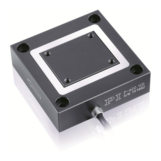
PIHera Brand name Warning sign "Observe manual!" Old equipment disposal (p. 53) Country of origin: Germany Country of origin WWW.PI.WS Manufacturer's address (website) CE conformity mark Manufacturer's logo Symbol for the protective earth conductor (p. 25) P-62x Positioning Systems PZ234E... -
Page 18: Scope Of Delivery
3 Product Description If applicable: The arrows indicate the positive direction of motion. The letter X, Y, and Z indicate the axis. Figure 2: "Residual Voltage" warning sign on the connector of the P-62x "Residual Voltage" warning: Risk of electric shock (p. 5) for models with Sub-D plug connector Scope of Delivery Product number Components... -
Page 19: Suitable Electronics
3 Product Description Suitable Electronics To operate a P-62x, you need suitable electronics. Selection of the device depends on the application and the connections available. Electronics Connector* Channels** E-505 piezo amplifier module LEMO E-610 piezo amplifier / servo controller (OEM module) LEMO E-503 piezo amplifier module LEMO... -
Page 20: Technical Features
3 Product Description Adapter cable for models with LEMO plug connectors Product number Description P-895.1LDC Adapter cable LEMO to Sub-D 7W2 (m) for piezo actuator nanopositioning systems with capacitive sensors, 1 channel, length: 0.3 m. P-895.3LDC Adapter cable LEMO to Sub-D 25W3 (m) for piezo actuator nanopositioning systems with capacitive sensors, 3 channels, length: 0.3 m. -
Page 21: Capacitive Sensors
3 Product Description 3.7.3 Capacitive Sensors Except for the models P-62x.x0L, all P-62x are equipped with capacitive sensors. Capacitive sensors measure the position directly on the motion platform (direct metrology) and work without contact. Neither friction nor hysteresis interferes with the motion, which allows excellent linearity values to be achieved together with the high position resolution. -
Page 23: Unpacking
When handling the vacuum version of the positioner, attention must be paid to appropriate cleanliness. At PI, all parts are cleaned before assembly. Powder-free gloves are worn during assembly and measuring. In addition, the positioner is wipe cleaned afterwards and then shrink-wrapped twice in vacuum-compatible film. -
Page 25: Installation
Do not open the P-62x. Discharge the positioner's piezo actuators before installation: Connect the positioner to the switched-off PI controller, which is equipped with an internal discharge resistor. Do not pull the plug connector out of the electronics during operation. -
Page 26: Mounting The Positioner And Affixing The Load
NOTICE Damage due to unsuitable cables! Unsuitable cables can damage the P-62x and the electronics. Only use cables provided by PI for connecting the P-62x to the electronics. NOTICE Damage due to incorrectly tightened screws! Incorrectly tightened screws can cause damage. - Page 27 5 Installation NOTICE Warping of the P-62x due to mounting on uneven surfaces! Mounting the P-62x onto an uneven surface can warp the P-62x. Warping reduces the accuracy. Mount the P-62x onto an even surface. The recommended evenness of the surface is ≤20 µm.
- Page 28 5 Installation Center of load at an unsuitable position: Figure 4: Tall load and center of load too far above the motion platform Figure 5: Unwanted lever effect and center of load on the side of the motion platform Requirements ...
-
Page 29: Connecting The P-62X To The Protective Earth Conductor
5 Installation Mounting the P-62x and affixing the load 1. Alignment (optional): − Align the positioner using the locating holes (p. 47) in the base body and suitable dowel pins. − Align the load using the locating holes (p. 47) in the motion platform of the P-62x and suitable dowel pins. - Page 30 5 Installation Separate protective earth connection available If a separate protective earth connection is available, it must be used. Figure 6: Protective earth connection No separate protective earth connection If a separate protective earth connection is not available, all mounting holes marked with the protective earth conductor symbol must be used to ensure proper connection of the protective earth conductor.
- Page 31 5 Installation Connecting the protective earth conductor to the separate protective earth connection (all models except P-620 and P-621.2xx/.2U) Figure 8: Connecting the protective earth conductor (profile view) Base body of the P-62x Flat washer Safety washer Screw Cable lug Protective earth conductor 1.
- Page 32 5 Installation Connecting the protective earth conductor via the mounting holes (P-620 and P-621.2xx/.2U only) Figure 9: Positioner on a surface that must be connected to a protective earth conductor; for mounting holes, see arrows. 1. Optional: Align the positioner using the locating holes (p. 47) in the base body and the dowel pins supplied.
-
Page 33: Connecting The Vacuum Version To The Electronics
5 Installation Connecting the Vacuum Version to the Electronics INFORMATION This section describes connection of the vacuum version of the P-62x to electronics with Sub-D 7W2 socket. For connecting electronics with Sub-D 25W3, you also need a suitable P-895 adapter cable (p. 15) that is connected to the Sub-D 25W3 socket of the electronics. Requirements ... - Page 34 5 Installation Figure 10: Connection of the .1U vacuum version to the electronics with P-890.1CV vacuum feedthrough Figure 11: Connection of the .2U vacuum version to the electronics with P-890.2CV vacuum feedthrough Version: 1.1.0 PZ234E P-62x Positioning Systems...
-
Page 35: Startup And Operation
6 Startup and Operation Startup and Operation In this Chapter General Notes on Startup and Operation ..................31 Operating the P-62x ........................33 Discharging the P-62x ........................33 General Notes on Startup and Operation CAUTION Risk of electric shock if the protective earth conductor is not connected! If a protective earth conductor is not or not properly connected, dangerous touch voltages can occur on the P-62x in the case of malfunction or failure of the system. - Page 36 6 Startup and Operation NOTICE Reduced lifetime of the piezo actuator due to permanently high voltage! The permanent application of a high static voltage to piezo actuators leads to a considerable reduction in the lifetime of the piezo ceramic. When the P-62x is not used but the electronics remain switched on to ensure temperature stability, discharge the P-62x (p.
-
Page 37: Operating The P-62X
Before demounting (e.g., before cleaning and transporting the P-62x and for modifications) The P-62x is discharged via the internal discharge resistor of the controller from PI. Discharging an P-62x that is connected to the controller In closed-loop operation: 1. Switch off the servo mode on the controller. -
Page 39: Maintenance
7 Maintenance Maintenance In this Chapter General Notes on Maintenance ....................35 Cleaning the P-62x ........................35 General Notes on Maintenance NOTICE Misalignment from loosening screws! The P-62x is maintenance-free and achieves its positioning accuracy as a result of the optimum alignment of mechanical components and piezo actuators. -
Page 41: Troubleshooting
8 Troubleshooting Troubleshooting Problem Possible causes Solution No or limited Cable not connected Check the cable connections. motion correctly Excessive load Do not exceed the maximum permissible stress and load capacities according to the specifications (p. 41). Zero shift of the sensor for ... - Page 42 8 Troubleshooting Problem Possible causes Solution P-62x or controller has been When using positioners, whose ID chip does replaced not contain any calibration data, or LEMO plug connectors, axis displacement has to be recalibrated after the P-62x or the controller has been replaced.
-
Page 43: Customer Service
9 Customer Service Customer Service For inquiries and orders, contact your PI sales engineer or send us an email (service@pi.de). If you have questions concerning your system, have the following information ready: − Product and serial numbers of all products in the system −... -
Page 45: Technical Data
10 Technical Data Technical Data In this Chapter Specifications ..........................41 Dimensions ..........................47 Torque for Stainless Steel Screws (A2-70) ................... 50 Pin Assignment ..........................50 10.1 Specifications 10.1.1 Data Table P-620.1CD P-621.1CD P-622.1CD P-625.1CD P-628.1CD P-629.1CD Unit Tole- rance P-620.1CL P-621.1CL P-622.1CL... - Page 46 * With digital controller. With analog controllers 0.05 %. ** With digital controller. With analog controllers 0.07 %. The resolution of the system is limited only by the noise of the amplifier and the measuring technology because PI piezo nanopositioning systems are free of friction.
- Page 47 * With digital controller. With analog controllers 0.05 %. ** With digital controller. With analog controllers 0.07 %. The resolution of the system is limited only by the noise of the amplifier and the measuring technology because PI piezo nanopositioning systems are free of friction.
- Page 48 10 Technical Data P-620.ZCD / P-621.ZCD / P-622.ZCD / Unit Tolerance P-620.ZCL P-621.ZCL P-622.ZCL Active axes Motion and positioning Integrated sensor Capacitive Capacitive Capacitive Travel range at -20 to 120 V, open loop 65 µm +20 % / -0 % Travel range, closed loop µm Resolution, open loop...
-
Page 49: Materials Used For Vacuum-Compatible Models
10 Technical Data 10.1.2 Materials Used for Vacuum-Compatible Models The following vacuum-compatible materials were used for the .1U and .2U vacuum versions of the P-62x: Stainless steel, aluminum, AI , titanium, piezoceramic, FEP, PEEK Bakeout temperature: 130 °C For more information, contact our customer service department (p. 39). 10.1.3 Maximum Ratings P-62x positioners are designed for the following operating data:... -
Page 50: Ambient Conditions And Classifications
10 Technical Data 10.1.4 Ambient Conditions and Classifications The following ambient conditions and classifications for the P-62x must be observed: Area of application For indoor use only Maximum altitude 2000 m Air pressure All models except vacuum- Vacuum-compatible models: compatible models: 1100 hPa to 10 1100 hPa to 0.1 hPa Relative humidity... -
Page 51: Dimensions
10 Technical Data 10.2 Dimensions Dimensions in mm. Note that the decimal places are separated by a comma in the drawings. Figure 12: P-62x.1CD / .1CL / .10L / .1U The P-620 does not have a separate protective earth connection. P-620.1xx P-621.1x(x) P-622.1x(x) - Page 52 10 Technical Data Figure 13: P-62x.2CD / .2CL / .20L / .2U The P-620 and the P-621.2xx/.2U do not have a separate protective earth connection. Ø F P-620.2xx 21.5 1.01 1.5 M2 3.5 5.1 2.2 9 P-621.2x(x) 1.51 2.5 M3 5 6.25 3.2 10 P-622.2x(x)
- Page 53 10 Technical Data Figure 14: P-62x.ZCD / .ZCL / .Z0L The P-620 does not have a separate protective earth connection. Ø F P-620.Zxx 1.01 M2 28 P-621.Zxx 17.5 1.51 M3 36.5 P-622.Zxx 17.5 1.51 M3 46.5 P-62x Positioning Systems PZ234E Version: 1.1.0...
-
Page 54: Torque For Stainless Steel Screws (A2-70)
10 Technical Data 10.3 Torque for Stainless Steel Screws (A2-70) Screw size Minimum torque Maximum torque 4 Nm 6 Nm 2.5 Nm 3.5 Nm 1.5 Nm 2.5 Nm 0.8 Nm 1.1 Nm M2.5 0.3 Nm 0.4 Nm 0.15 Nm 0.2 Nm M1.6 0.06 Nm 0.12 Nm... - Page 55 10 Technical Data Signal Function Piezo voltage Probe Probe sensor signal (nonmoving part of the capacitive sensor) Data ID chip Data line for ID chip GND target and ID chip Ground of target and ID chip GND PZT Piezo voltage ground (Not connected) Target Target sensor signal (movable part of the...
- Page 56 10 Technical Data LEMO coaxial connectors Figure 18: LEMO connectors: PZT, P and T Connector Signal Function Connector shell Probe Probe sensor signal (nonmoving Cable shield part of the capacitive sensor) Target Target sensor signal (movable part Cable shield of the capacitive sensor) Piezo voltage Piezo voltage ground on cable shield...
-
Page 57: Old Equipment Disposal
Dispose of your old equipment according to international, national, and local rules and regulations. In order to fulfil its responsibility as the product manufacturer, Physik Instrumente (PI) GmbH & Co. KG undertakes environmentally correct disposal of all old PI equipment made available on the market after 13 August 2005 without charge. - Page 59 12 EU Declaration of Conformity EU Declaration of Conformity For the P-62x, an EU Declaration of Conformity has been issued in accordance with the following European directives: Low Voltage Directive EMC Directive RoHS Directive The applied standards certifying the conformity are listed below. Safety (Low Voltage Directive): EN 61010-1 EMC: EN 61326-1 RoHS: EN 50581...
Need help?
Do you have a question about the P-62 Series and is the answer not in the manual?
Questions and answers