Table of Contents
Advertisement
Quick Links
PZ248E
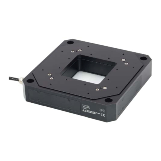
P-56x Nanopositioners
User Manual
Version: 1.0.0
Date: 22.11.2013
This document describes the following
products:
P-561
PIMars XYZ Nanopositioning System
P-561.3CD/.3CL, 100 µm × 100 µm × 100 µm
P-561.3DD, 45 µm × 45 µm × 15 µm, Direct
Drive
P-562
PIMars XYZ Nanopositioning System
P-562.3CD/.3CL, 200 µm × 200 µm × 200 µm
P-563
PIMars XYZ Nanopositioning System
P-563.3CD/.3CL, 300 µm × 300 µm × 300 µm
.3CD/.3DD with Sub-D connector
.3CL with LEMO connectors
Physik Instrumente (PI) GmbH & Co. KG · Auf der Römerstr. 1 76228 Karlsruhe, Germany
Phone +49 721 4846-0 · Fax +49 721 4846-1019 · E-mail info@pi.ws
Advertisement
Table of Contents


Need help?
Do you have a question about the P-56 Series and is the answer not in the manual?
Questions and answers