Table of Contents
Advertisement
Quick Links
PZ253E
P611 Positioners
User Manual
Version: 1.2.0
Physik Instrumente (PI) GmbH & Co. KG, Auf der Roemerstrasse 1, 76228 Karlsruhe, Germany
Phone +49 721 4846-0, Fax +49 721 4846-1019, Email info@pi.ws, www.pi.ws
Date: 13.04.2021
This document describes the following products:
P611.1
Linear nanopositioner
P-611.1S/.10
P611.XZ / P611.2
XZ and XYZ nanopositioner
P-611.2S/.20/.XZS/.XZ0
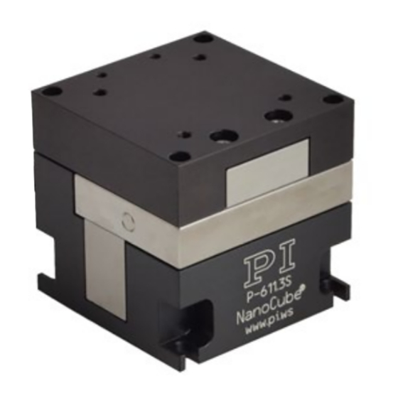
P611.3
NanoCube® XYZ nanopositioner
P-611.3S/.3SF/.3O/.3OF
P611.Z
Vertical nanopositioning stage
P-611.ZS/.Z0
.1S/.10/.2S/.20/.XZS/.XZ0/.ZS/.Z0
= with LEMO connector(s)
.3S/.3SF/.3O/.3OF
= with D-sub connector
Advertisement
Table of Contents

Related Manuals for PI P611


Summary of Contents for PI P611
- Page 1 Vertical nanopositioning stage P-611.ZS/.Z0 .1S/.10/.2S/.20/.XZS/.XZ0/.ZS/.Z0 = with LEMO connector(s) .3S/.3SF/.3O/.3OF = with D-sub connector Physik Instrumente (PI) GmbH & Co. KG, Auf der Roemerstrasse 1, 76228 Karlsruhe, Germany Phone +49 721 4846-0, Fax +49 721 4846-1019, Email info@pi.ws, www.pi.ws...
- Page 2 The patents held by PI are found in our patent list: https://www.physikinstrumente.com/en/about-pi/patents © 2021 Physik Instrumente (PI) GmbH & Co. KG, Karlsruhe, Germany. The text, photographs and drawings in this manual are protected by copyright. With regard thereto, Physik Instrumente (PI) GmbH & Co. KG retains all the rights.
-
Page 3: Table Of Contents
Contents About this Document Objective and Target Group of this User Manual ............1 Symbols and Typographic Conventions..............1 Definition of Terms ..................... 2 Figures ........................2 Other Applicable Documents ..................3 Downloading Manuals ....................3 Safety Intended Use ......................5 General Safety Instructions .................. - Page 4 Maintenance General Notes on Maintenance ................29 Cleaning the P-611 ....................29 Troubleshooting Customer Service Technical Data 10.1 Specifications ......................35 10.1.1 Data Table ....................35 10.1.2 Maximum Ratings ..................40 10.1.3 Ambient Conditions and Classifications ............41 10.2 Dimensions ....................... 42 10.3 Torque for Stainless Steel Screws (A2-70) ..............
-
Page 5: About This Document
1 About this Document About this Document In this Chapter Objective and Target Group of this User Manual ................1 Symbols and Typographic Conventions ..................1 Definition of Terms ........................2 Figures ............................2 Other Applicable Documents ......................3 Downloading Manuals ........................3 Objective and Target Group of this User Manual This user manual contains the information required for using the P-611 as intended ("x"... -
Page 6: Definition Of Terms
1 About this Document Symbol/Label Meaning Action consisting of several steps with strict sequential order Action consisting of one or more steps without relevant sequential order. Bullet p. 5 Cross-reference to page 5 RS232 Label on the product indicating an operating element (example: RS-232 interface socket) Warning signs attached to the product that refer to detailed information in this manual. -
Page 7: Other Applicable Documents
1 About this Document Other Applicable Documents The devices and software tools from PI mentioned in this documentation are described in separate manuals. Product Document E-503 Piezo Amplifier Module PZ62E User Manual E-505 Piezo Amplifier Module E-610 Piezo Amplifier/Servo Controller (OEM Module) -
Page 9: Safety
It is only possible to use the P-611 as intended in conjunction with suitable electronics (p. 13) from PI. The electronics are not included in the scope of delivery of the P-611. The electronics must provide the required operating voltages. To ensure proper performance of the servo control system, the electronics must also be able to read out and process the signals from the position sensors. -
Page 10: General Safety Instructions
Do not open the P-611. Discharge the positioner's piezo actuators before installing: Connect the positioner to the switched-off PI electronics equipped with an internal discharge resistor. Do not pull the plug connector out of the electronics during operation. -
Page 11: Organizational Measures
2 Safety Mechanical forces can damage or misalign the P-611. Avoid impacts that affect the P-611. Do not drop the P-611. Do not exceed the maximum permissible stress and load capacities according to the specifications (p. 35). ... -
Page 13: Product Description
3 Product Description Product Description In this Chapter Model Overview ..........................9 Product View ..........................10 Product Labeling .......................... 12 Scope of Delivery ......................... 12 Suitable Electronics ........................13 Accessories ........................... 13 Technical Features ........................14 Model Overview The following standard versions of the P-611 are available: P611.1: Linear nanopositioner Model Description... -
Page 14: Product View
3 Product Description P611.Z: Vertical nanopositioning stage Model Description P-611.ZS Vertical nanopositioning stage, 100 µm, strain gauge sensor P-611.Z0 Vertical nanopositioning stage, 120 µm, without sensor Product View The figures serve as examples and can differ from your positioner model. Figure 1: Example of product view Motion platform... - Page 15 3 Product Description Direction of motion of the P611 The arrows indicate the positive direction of motion in each case. P-611.1x P-611.Zx P-611.2x P-611.XZx P-611.3x / P-611.3xF P611 Positioners PZ253E Version: 1.2.0...
-
Page 16: Product Labeling
Brand name (.3x and .3xF models only) Country of origin: Germany Country of origin Warning sign "Pay attention to the manual!" Old equipment disposal (p. 53) WWW.PI.WS Manufacturer's address (website) Manufacturer's logo CE conformity mark Symbol for the protective earth conductor, marks the protective earth connector of the P-611 (p. -
Page 17: Suitable Electronics
3 Product Description Suitable Electronics You need suitable electronics to operate a P-611. Selecting the device depends on the application and the connectors available. Electronics Connector* Channels** E-505 Piezo Amplifier Module LEMO E-610 Piezo Amplifier / Servo Controller (OEM module) LEMO E-836 Piezo Amplifier LEMO E-503 Piezo Amplifier Module... -
Page 18: Technical Features
3 Product Description Technical Features 3.7.1 PICMA® Piezo Actuators P-611 positioners are driven by PICMA® piezo actuators. PICMA® actuators have all-ceramic insulation and their performance and lifetime are therefore far superior to conventional actuators. The ceramic insulation layer protects the monolithic piezoceramic block against humidity and failure due to increased leakage current. -
Page 19: Unpacking
2. Compare the contents of the shipment with the items listed in the contract and the delivery note. 3. Inspect the contents for signs of damage. If there is any sign of damage or missing parts, contact PI immediately. 4. Keep all packaging materials in case the product needs to be returned. P611 Positioners PZ253E Version: 1.2.0... -
Page 21: Installation
Do not open the P-611. Discharge the positioner's piezo actuators before installing: Connect the positioner to the switched-off PI electronics equipped with an internal discharge resistor. Do not pull the plug connector out of the electronics during operation. -
Page 22: Connecting The P-611 To The Protective Earth Conductor
NOTICE Damage due to unsuitable cables! Unsuitable cables can damage the P-611 and the electronics. Use cables provided by PI only to connect the P-611 to the electronics. NOTICE Damage due to improper mounting! Improper mounting of the P-611 or incorrectly mounted parts can damage the P-611. - Page 23 5 Installation The P-611 has an M4 hole for attaching the protective earth conductor . This hole is marked with the symbol for the protective earth conductor . For the exact position of the hole, see "Dimensions" (p. 42). Requirements ...
-
Page 24: Mounting The P-611
5 Installation Mounting the P611 NOTICE Warping the P611 when mounting onto uneven surfaces! The P-611 could warp if mounted on an uneven surface. Warping reduces the accuracy. Mount the P-611 onto a flat surface. The recommended flatness of the surface is ≤20 µm. ... - Page 25 5 Installation Figure 6: P-611.XZx, .3x, .3xF, and .Zx: One of four recesses in the base body for mounting the positioner onto an underlying surface Requirements You have read and understood the general notes on installation (p. 17). The P-611 is not connected to the electronics. Tools and accessories When mounting a P-611.2x: ...
-
Page 26: Fixing The Load
5 Installation Fixing the Load NOTICE Mechanical overload of the platform! High torques during fastening of the load as well as high loads can overload the platform of the P-611. Mechanical overload can cause damage to the piezo actuators, sensors, and flexures of the P-611 and lead to loss of accuracy. - Page 27 5 Installation INFORMATION Positive direction of axis motion is specified in the product view (p. 10). Center of load at the optimal position: Figure 7: Example of an optimally placed load Center of load at an unsuitable position: Figure 8: Tall load and center of load too far above the platform Figure 9: Unwanted lever effect and center of load on the side of the platform...
- Page 28 5 Installation Tools and accessories Screws of suitable size and length (p. 42) Suitable screwdriver Fixing the load 1. Align the load on the P-611 so that the mounting holes in the load and the holes in the platform are in line.
-
Page 29: Starting And Operating
6 Starting and Operating Starting and Operating In this Chapter General Notes on Starting ......................25 Operating the P-611 ........................26 Discharging the P-611 ........................27 General Notes on Starting CAUTION Risk of electric shock if the protective earth conductor is not connected! If a protective earth conductor is not or not properly connected, dangerous touch voltages can occur on the P-611 in the case of malfunction or failure of the system. -
Page 30: Operating The P-611
Operating voltages that are too high or incorrectly connected can cause damage to the P-611. Operate the P-611 only with controllers/drivers and original accessories from PI. Do not exceed the operating voltage range (p. 40) for which the P-611 is specified. -
Page 31: Discharging The P-611
Before demounting (e.g., before cleaning and transporting the P-611 and for modifications) The P-611 is discharged via the discharge resistor inside the electronics from PI. Discharging a Positioner Connected to the Electronics In closed-loop operation: 1. Switch off the servo mode on the controller. -
Page 33: Maintenance
7 Maintenance Maintenance In this Chapter General Notes on Maintenance ....................29 Cleaning the P-611 ........................29 General Notes on Maintenance NOTICE Misalignment due to loosening screws! The P-611 is maintenance-free and achieves its positioning accuracy as a result of the optimal alignment of mechanical components and piezo actuators. -
Page 35: Troubleshooting
8 Troubleshooting Troubleshooting Problem Possible causes Solution No or limited Cable not connected Check the cable connections. motion correctly Excessive load Do not exceed the maximum permissible stress and load capacities according to the specifications (p. 35). Zero shift of the sensor for ... - Page 36 8 Troubleshooting Problem Possible causes Solution Axes were mixed up during Pay attention to the assignment of the connection (only with LEMO axes when connecting the positioner to connectors) the controller. This assignment is indicated by labels on the devices. The positioner is not ...
-
Page 37: Customer Service
9 Customer Service Customer Service For inquiries and orders, contact your PI sales engineer or send us an email (service@pi.de). If you have any questions concerning your system, provide the following information: − Product and serial numbers of all products in the system −... -
Page 39: Technical Data
10 Technical Data Technical Data In this Chapter Specifications ..........................35 Dimensions ..........................42 Torque for Stainless Steel Screws (A2-70) ................... 49 Pin Assignment ..........................49 10.1 Specifications 10.1.1 Data Table P611.1S P611.10 Unit Tolerance Active axes Motion and positioning Integrated sensor Travel range at -20 to +20 % /... - Page 40 E-625, E-665, E-625, E-665, E-836 E-836 The resolution of the system is limited only by the noise of the amplifier and the measuring technology because PI piezo nanopositioning systems are free of friction. P611.2S P611.20 P611.XZS P611.XZ0 Unit Tolerance Active axes...
- Page 41 E-664, E-664, E-664, E-664, E-727 E-727 E-727 E-727 The resolution of the system is limited only by the noise of the amplifier and the measuring technology because PI piezo nanopositioning systems are free of friction. P611 Positioners PZ253E Version: 1.2.0...
- Page 42 10 Technical Data P611.3S P611.3O Unit Tolerance P611.3SF P611.3OF Active axes X, Y, Z X, Y, Z Motion and positioning Integrated sensor Travel range at -20 to 120 V, 120 / axis 120 / axis µm +20 % / open loop -0 % Travel range, closed loop 100 / axis...
- Page 43 E-664, E-727 The resolution of the system is limited only by the noise of the amplifier and the measuring technology because PI piezo nanopositioning systems are free of friction. Adapter cables with LEMO connectors for sensor and operating voltage available.
-
Page 44: Maximum Ratings
E-665, E-836 The resolution of the system is limited only by the noise of the amplifier and the measuring technology because PI piezo nanopositioning systems are free of friction. System properties: System configuration: P-611.ZS and E-665.SR controller with 30 g load... -
Page 45: Ambient Conditions And Classifications
10 Technical Data 10.1.3 Ambient Conditions and Classifications Pay attention to the following ambient conditions and classifications for the P-611: Area of application For indoor use only Maximum altitude 2000 m Air pressure 1100 hPa to 0.1 hPa Relative humidity Highest relative humidity 80 % for temperatures up to 31 °C Decreasing linearly to 50 % relative humidity at 40 °C Operating temperature... -
Page 46: Dimensions
10 Technical Data 10.2 Dimensions Dimensions in mm. Note that a comma is used in the drawings instead of a decimal point. Figure 10: P-611.1S Version: 1.2.0 PZ253E P611 Positioners... - Page 47 10 Technical Data Figure 11: P-611.10 P611 Positioners PZ253E Version: 1.2.0...
- Page 48 10 Technical Data Figure 12: P-611.2S and P-611.20 Version: 1.2.0 PZ253E P611 Positioners...
- Page 49 10 Technical Data Figure 13: P-611.XZS and P-611.XZ0 P611 Positioners PZ253E Version: 1.2.0...
- Page 50 10 Technical Data Figure 14: P-611.3O, P-611.3S, P-611.3OF and P-611.3SF P-611.3O 38.2 37.8 43.2 P-611.3S 38.2 37.8 43.2 P-611.3OF 38.2 37.8 44.2 P-611.3SF 44.2 Version: 1.2.0 PZ253E P611 Positioners...
- Page 51 10 Technical Data Figure 15: P-611.ZS P611 Positioners PZ253E Version: 1.2.0...
- Page 52 10 Technical Data Figure 16: P-611.Z0 Version: 1.2.0 PZ253E P611 Positioners...
-
Page 53: Torque For Stainless Steel Screws (A2-70)
10 Technical Data 10.3 Torque for Stainless Steel Screws (A270) Screw size Minimum torque Maximum torque 4 Nm 6 Nm 2.5 Nm 3.5 Nm 1.5 Nm 2.5 Nm 0.8 Nm 1.1 Nm M2.5 0.3 Nm 0.4 Nm 0.15 Nm 0.2 Nm M1.6 0.06 Nm 0.12 Nm... - Page 54 10 Technical Data Signal Function SGS 3 GND Output SGS 2-B2 sensor signal SGS 2 GND Output SGS 1-B2 sensor signal SGS 1 GND 20 to 22 Free Input Piezo voltage –, channel 3, Z axis Input Piezo voltage –, channel 2, Y axis Input Piezo voltage –, channel 1, X axis Dsub 25 connector pin assignment for the P611.3O/.3OF...
- Page 55 10 Technical Data LEMO connectors Only for P-611.1S/.10/.2S/.20/.XZS/.XZ0/.ZS/.Z0 Figure 18: LEMO connector (side view) LEMO connectors according to model (one connector per axis) P611 Connector Signal Function Connector model (front view) shell .1S / .10 Inner Input Piezo voltage Ground .2S / .20 connecto -20 to 120 V...
-
Page 57: Old Equipment Disposal
Dispose of your old equipment according to international, national, and local rules and regulations. In order to fulfil its responsibility as the product manufacturer, Physik Instrumente (PI) GmbH & Co. KG undertakes environmentally correct disposal of all old PI equipment made available on the market after 13 August 2005 without charge. - Page 59 12 EU Declaration of Conformity EU Declaration of Conformity For the P-611, an EU Declaration of Conformity has been issued in accordance with the following European directives: Low Voltage Directive EMC Directive RoHS Directive The applied standards certifying the conformity are listed below. Safety (Low Voltage Directive): EN 61010-1 EMC: EN 61326-1 RoHS: EN 50581 or EN IEC 63000...
Need help?
Do you have a question about the P611 and is the answer not in the manual?
Questions and answers