Table of Contents
Advertisement
Quick Links
PZ103E
P-73x Nanopositioner
User Manual
Version: 1.2.0
Physik Instrumente (PI) GmbH & Co. KG, Auf der Römerstraße 1, 76228 Karlsruhe, Germany
Phone +49 721 4846-0, fax +49 721 4846-1019, e-mail info@pi.ws, www.pi.ws
Date: 16.05.2024
This document describes the following products:
P-733.2
XY nanopositioner
P-733.2CD/.2CL, 100 µm × 100 µm
P-733.2DD, 30 µm × 30 µm, high dynamics,
direct drive
P-734.2
XY nanopositioner
P-734.2CD/.2CL, 100 µm × 100 µm, very high
travel accuracy
P-733.3
XYZ nanopositioner
P-733.3CD/.3CL, 100 µm × 100 µm × 10 µm
P-733.3DD, 30 µm × 30 µm × 10 µm, high
dynamics, direct drive
P-733.Z
Nanopositioner Z stage
P-733.ZCD/.ZCL, 100 µm
.2CD/.3CD/.2DD/.3DD with D-sub 25W3
connector (m)
.ZCD with D-sub 7W2 connector (m)
.2CL/.3CL/.ZCL with LEMO connector (m)
Advertisement
Table of Contents

Related Manuals for PI P-73 Series


Summary of Contents for PI P-73 Series
- Page 1 .2CD/.3CD/.2DD/.3DD with D-sub 25W3 connector (m) .ZCD with D-sub 7W2 connector (m) .2CL/.3CL/.ZCL with LEMO connector (m) Physik Instrumente (PI) GmbH & Co. KG, Auf der Römerstraße 1, 76228 Karlsruhe, Germany Phone +49 721 4846-0, fax +49 721 4846-1019, e-mail info@pi.ws, www.pi.ws...
- Page 2 PI®, NanoCube®, PICMA®, PILine®, NEXLINE®, PiezoWalk®, NEXACT®, Picoactuator®, PInano®, PIMag®, Q-Motion® © 2024 Physik Instrumente (PI) GmbH & Co. KG, Karlsruhe, Germany. The text, photographs and drawings in this manual are protected by copyright. With regard thereto, Physik Instrumente (PI) GmbH & Co. KG retains all the rights.
-
Page 3: Table Of Contents
Contents About this Document Objective and Target Group of this User Manual ............1 Symbols and Typographic Conventions..............1 Definition of Terms ..................... 2 Figures ........................2 Other Applicable Documents ..................3 Downloading Manuals ....................3 Safety Intended Use ......................5 General Safety Instructions .................. - Page 4 Discharging the P-73x ....................27 Maintenance General Notes on Maintenance ................29 Cleaning the P-73x ....................29 Troubleshooting Customer Service Department Technical Data 10.1 Specifications ......................35 10.1.1 Data Table ....................35 10.1.2 Maximum Ratings ..................42 10.1.3 Ambient Conditions and Classifications ............42 10.2 Dimensions .......................
-
Page 5: About This Document
1 About this Document About this Document In this Chapter Objective and Target Group of this User Manual ................1 Symbols and Typographic Conventions ..................1 Definition of Terms ........................2 Figures ............................2 Other Applicable Documents ......................3 Downloading Manuals ........................3 Objective and Target Group of this User Manual This user manual contains the information required for using the P-73x as intended ("x"... -
Page 6: Definition Of Terms
1 About this Document Symbol/ Meaning Label Action consisting of several steps with strict sequential order Action consisting of one or more steps without relevant sequential order. Bullet point p. 5 Cross-reference to page 5 RS-232 Label on the product indicating an operating element (example: RS-232 interface socket) Warning signs on the product that refer to detailed information in this manual. -
Page 7: Other Applicable Documents
1 About this Document Other Applicable Documents The devices and software tools from PI mentioned in this documentation are described in separate manuals. Product Document E-503 piezo amplifier module PZ62E user manual E-505 piezo amplifier module E-610 piezo amplifier/servo controller (OEM... -
Page 9: Safety
The P-73x can only be used as intended in conjunction with suitable electronics (p. 13) available from PI. The electronics are not in the P-73x's scope of delivery. The electronics must provide the required operating voltages. To ensure proper performance of the servo control system, the electronics must be able to read out and process the signals from the capacitive sensors. - Page 10 Do not open the P-73x. Discharge the positioner's piezo actuators before installing: Connect the positioner to the switched-off PI electronics equipped with an internal discharge resistor. Do not pull the plug connector out of the electronics during operation.
-
Page 11: Organizational Measures
2 Safety Organizational Measures User manual Always keep this user manual together with the P-73x. The latest versions of the user manuals are available for download on our website (p. 3). Add all information from the manufacturer such as supplements or technical notes to the user manual. -
Page 13: Product Description
3 Product Description Product Description In this Chapter Model Overview ..........................9 Product View ..........................10 Product Labeling .......................... 12 Scope of Delivery ......................... 12 Suitable Electronics ........................13 Optional Accessories ........................13 Technical Features ........................14 Model Overview The P-73x is available in the following versions: XY Nanopositioners Model Description... -
Page 14: Product View
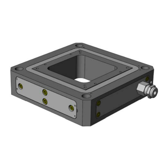
3 Product Description XYZ Nanopositioners with Direct Drive Model Description P-733.3DD XYZ piezo nanopositioner; 30 µm × 30 µm × 10 µm travel range (X × Y × Z); direct drive; capacitive, indirect position measuring; D-sub 25W3 (m); 1.5 m cable length Nanopositioner Z Stages Model... - Page 15 3 Product Description Figure 2: P-734: Exemplary product view Motion platform Base body Protective earth connector Cable exit Direction of P-73x motion The arrows indicate the positive direction of motion in each case. P-733 XY nanopositioners: P-734 XY nanopositioners: P-733 XYZ nanopositioners P-733 nanopositioner Z stages: P-73x Nanopositioner PZ103E...
-
Page 16: Product Labeling
Warning sign "Pay attention to the manual!" Old equipment disposal (p. 53) CE conformity mark Country of origin: Germany Country of origin WWW.PI.WS Manufacturer's address (website) Symbol for the protective earth conductor (p. 18) If applicable: The arrows indicate the positive direction of motion. -
Page 17: Suitable Electronics
3 Product Description Suitable Electronics You need suitable electronics to operate a P-73x. Selecting the device depends on the application and the connectors available. Electronics Connector* Channels** E-505 Piezo Amplifier Module LEMO E-610 Piezo Amplifier / Servo Controller (OEM Module) LEMO E-503 Piezo Amplifier Module LEMO E-621 Piezo Amplifier / Servo Controller Module... -
Page 18: Technical Features
3 Product Description Adapter plates Product number Description P-733.AP1 Adapter plate for mounting P-733 piezo stages onto M-545 XY stages and U-760 XY stage systems To order, contact our customer service department (p. 33). Technical Features 3.7.1 PICMA® Piezo Actuators P-73x positioners are driven by PICMA®... -
Page 19: Unpacking
4 Unpacking Unpacking NOTICE Mechanical overload due to incorrect handling! An impermissible mechanical load on the motion platform of the P-73x can cause damage to the piezo actuators, sensors, and flexures of the P-73x as well as loss of accuracy. ... -
Page 21: Installing
Do not open the P-73x. Discharge the positioner's piezo actuators before installing: Connect the positioner to the switched-off PI electronics equipped with an internal discharge resistor. Do not pull the plug connector out of the electronics during operation. -
Page 22: Connecting The P-73X To The Protective Earth Conductor
NOTICE Damage due to unsuitable cables! Unsuitable cables can damage the P-73x and the electronics. Use cables provided by PI only to connect the P-73x to the electronics. NOTICE Damage due to improper mounting! Improper mounting of the P-73x or incorrectly mounted parts can damage the P-73x. - Page 23 5 Installing INFORMATION In the case of P-73x positioners with D-sub connectors, ground loops can occur when the positioner is grounded via its protective earth connector as well as via the connecting cable's shielding for the electronics. If a ground loop occurs, contact our customer service department (p. 33). The P-73x has an M4 hole for connecting the protective earth conductor.
-
Page 24: Mounting The P-73X
5 Installing Connecting the P-73x to the protective earth conductor 1. If necessary, firmly attach a suitable cable lug to the protective earth conductor. 2. Use the M4 screw (together with the flat and lock washers) to attach the cable lug of the protective earth conductor to the threaded hole in the P-73x as shown in the profile view. -
Page 25: Fixing The Load
5 Installing Requirements You have read and understood the General Notes on Installation (p. 17). Tools and accessories Screws of suitable size and length (see "Dimensions" (p. 43)) Suitable tools Mounting the P-73x 1. Align the P-73x on the mounting surface so that the holes in the P-73x and mounting surface are in line. - Page 26 5 Installing NOTICE Center of load at unsuitable position! If the center of load is located too far away from the center of the motion platform (e.g., tall load and unwanted lever effect), the P-73x can be damaged, especially in dynamic operation, by high strain on the flexure guides, high torques, and oscillations.
- Page 27 5 Installing Figure 8: Unwanted lever effect and center of load on the side of the platform Requirements You have read and understood the General Notes on Installation (p. 17). The P-73x is not connected to the electronics. Tools and accessories Screws of suitable size and length (p.
-
Page 28: Connecting The P-73X To The Electronics
5 Installing Connecting the P-73x to the Electronics INFORMATION When connecting, pay attention to the assignment specified on the labeling of the sockets, plug connectors, and cables. Requirements You have read and understood the General Notes on Installation (p. 17). ... -
Page 29: Starting And Operating
6 Starting and Operating Starting and Operating In this Chapter General Notes on Starting and Operating ................... 25 Operating the P-73x ........................27 Discharging the P-73x ........................27 General Notes on Starting and Operating CAUTION Risk of electric shock if the protective earth conductor is not connected! If the protective earth conductor is not or not properly connected, dangerous touch voltages can occur on the P-73x in the event of a malfunction or failure of the system. - Page 30 Operating voltage excessively high or incorrectly connected! Excessively high or wrongly connected operating voltages can damage the P-73x. Operate the P-73x with controllers/drivers and original accessories from PI. Do not exceed the operating voltage range (p. 42) specified for the P-73x.
-
Page 31: Operating The P-73X
Before demounting (e.g., before cleaning and transporting the P-73x and for modifications) The P-73x is discharged via the discharge resistor inside the electronics from PI. Discharging a positioner connected to the electronics In closed-loop operation: 1. Switch off the servo mode on the controller. -
Page 33: Maintenance
7 Maintenance Maintenance In this Chapter General Notes on Maintenance ....................29 Cleaning the P-73x ........................29 General Notes on Maintenance NOTICE Misalignment from loosening screws! The P-73x is maintenance-free and achieves its positioning accuracy as a result of the optimal alignment of mechanical components and piezo actuators. -
Page 35: Troubleshooting
8 Troubleshooting Troubleshooting Problem Possible causes Solution No or limited Cable not connected Check the cable connections. motion correctly Excessive load Do not exceed the maximum permissible stress and load capacities according to the specifications (p. 35). Zero shift of the sensor for ... - Page 36 8 Troubleshooting Problem Possible causes Solution Axes were mixed up during Pay attention to the assignment of the connection (LEMO axes when connecting the positioner to connectors only) the controller. This assignment is indicated by labels on the devices. The positioner Servo control parameters 1.
-
Page 37: Customer Service Department
9 Customer Service Department Customer Service Department For inquiries and orders, contact your PI sales engineer or send us an email (service@pi.de). If you have questions concerning your system, provide the following information: Product and serial numbers of all products in the system −... -
Page 39: Technical Data
10 Technical Data Technical Data Subject to change. You can find the latest product specifications on the product web page at www.pi.ws (https://www.pi.ws). In this Chapter Specifications ..........................35 Dimensions ..........................43 Torque for Stainless Steel Screws (A2-70) ................... 48 Pin Assignment .......................... - Page 40 * With digital controller. With analog controllers, the typical linearity error for direct drive positioners can be up to 0.1 %. The resolution of the system is limited only by the noise of the amplifier and the measuring technology because PI piezo nanopositioning systems are free of friction.
- Page 41 10 Technical Data Motion P-733.3DD P-733.3CD P-733.3CL Tolerance Active axes X ǀ Y ǀ Z X ǀ Y ǀ Z X ǀ Y ǀ Z Travel range in X 30 µm 100 µm 100 µm Travel range in Y 30 µm 100 µm 100 µm Travel range in Z...
- Page 42 * With digital controller. With analog controllers, the typical linearity error for direct drive positioners can be up to 0.1 %. The resolution of the system is limited only by the noise of the amplifier and the measuring technology because PI piezo nanopositioning systems are free of friction.
- Page 43 Sensor connector LEMO FFA.00.250.CTLC 17 The resolution of the system is limited only by the noise of the amplifier and the measuring technology because PI piezo nanopositioning systems are free of friction. At PI, technical data is specified at 22 ±3 °C. Unless otherwise stated, the values are for unloaded conditions. Some properties are interdependent.
- Page 44 10 Technical Data Motion P-734.2CL P-734.2CD Tolerance Active axes X ǀ Y X ǀ Y Travel range in X 100 µm 100 µm Travel range in Y 100 µm 100 µm Travel range in X, open loop, at 110 µm 110 µm +20 / -0 % -20 to 120 V...
- Page 45 E-500, E-503, E-505, E-509 E-712, E-727 The resolution of the system is limited only by the noise of the amplifier and the measuring technology because PI piezo nanopositioning systems are free of friction. At PI, technical data is specified at 22 ±3 °C. Unless otherwise stated, the values are for unloaded conditions. Some properties are interdependent.
-
Page 46: Maximum Ratings
10 Technical Data 10.1.2 Maximum Ratings P-73x positioners are designed for the following operating data: Model Maximum operating Maximum operating Maximum power voltage frequency (unloaded) consumption P-733.2CD, -20 to +120 V 167 Hz (in X and Y) 20 W (in X and Y) P-733.2CL P-733.2DD -20 to +120 V... -
Page 47: Dimensions
10 Technical Data 10.2 Dimensions Dimensions in mm. Note that a comma is used in the drawings instead of a decimal point. Figure 9: P-733.2Cx P-73x Nanopositioner PZ103E Version: 1.2.0... - Page 48 10 Technical Data Figure 10: P-733.2DD Version: 1.2.0 PZ103E P-73x Nanopositioner...
- Page 49 10 Technical Data Figure 11: P-733.3Cx P-73x Nanopositioner PZ103E Version: 1.2.0...
- Page 50 10 Technical Data Figure 12: P-733.3DD Version: 1.2.0 PZ103E P-73x Nanopositioner...
- Page 51 10 Technical Data Figure 13: P-733.ZCx P-73x Nanopositioner PZ103E Version: 1.2.0...
-
Page 52: Torque For Stainless Steel Screws (A2-70)
10 Technical Data Figure 14: P-734.2Cx 10.3 Torque for Stainless Steel Screws (A2-70) Screw size Minimum torque Maximum torque 4 Nm 6 Nm 2.5 Nm 3.5 Nm 1.5 Nm 2.5 Nm 0.8 Nm 1.1 Nm M2.5 0.3 Nm 0.4 Nm 0.15 Nm 0.2 Nm M1.6... -
Page 53: Pin Assignment
10 Technical Data 10.4 Pin Assignment D-sub 25W3 connector (m) For P-73x.2CD/.2DD/.3CD/.3DD only: Figure 15: D-sub 25W3 connector (m): Front with connections Signal Function Probe sensor signal, channel 2 A1 inner conductor Output (immovable part of the capacitive sensor) A1 outer conductor GND Shielding for probe sensor signal, channel 2 A2 inner conductor Output Probe sensor signal, channel 3... - Page 54 10 Technical Data Signal Function Vacant – Input Piezo voltage -, channel 4 Input Piezo voltage -, channel 3 Input Piezo voltage -, channel 2 Input Piezo voltage -, channel 1 Shielding for target sensor signal, channel 1 Model-dependent assignment of the D-sub 25W3 connector (m) (X = used): Sensor signal Model Piezo voltage...
- Page 55 10 Technical Data D-sub 7W2 connector (m) For P-733.ZCD only: Figure 16: D-sub 7W2 (m) connector: Front with connections Signal Function A1 inner conductor Input Piezo voltage + A2 inner conductor Output Probe sensor signal (immovable part of the capacitive sensor) A2 outer conductor GND Shield Bidirectional...
-
Page 57: Old Equipment Disposal
Dispose of your old equipment according to international, national, and local rules and regulations. To fulfill the responsibility as the product manufacturer, Physik Instrumente (PI) GmbH & Co. KG undertakes environmentally correct disposal of all old PI equipment made available on the market after 13 August 2005 without charge. - Page 59 12 European Declarations of Conformity European Declarations of Conformity For the P-73x, declarations of conformity were issued according to the following European statutory requirements: Low Voltage Directive EMC Directive RoHS Directive The standards applied for certifying conformity are listed below. Safety (Low Voltage Directive): EN 61010-1 EMC: EN 61326-1 RoHS: EN IEC 63000...
Need help?
Do you have a question about the P-73 Series and is the answer not in the manual?
Questions and answers