Table of Contents
Advertisement
Quick Links
Advertisement
Table of Contents
Troubleshooting

Subscribe to Our Youtube Channel
Related Manuals for Ruijie Networks RG-S6220-48XS4QXSV1


Summary of Contents for Ruijie Networks RG-S6220-48XS4QXSV1
- Page 1 RG-S6220 Series Switches Hardware Installation and Reference Guide V1.06...
- Page 2 This document is provided “as is”. The contents of this document are subject to change without any notice. Please obtain the latest information through the Ruijie Networks website. Ruijie Networks endeavors to ensure content accuracy and will not shoulder any responsibility for losses and damages caused due to content omissions, inaccuracies or errors.
- Page 3 It is intended for the users who have some experience in installing and maintaining network hardware. At the same time, it is assumed that the users are already familiar with the related terms and concepts. Obtaining Technical Assistance Ruijie Networks Website: http://www.ruijienetworks.com/ Service Email: service_rj@ruijienetworks.com ...
-
Page 4: Product Overview
1 Product Overview The RG-S6220 series switches are the data center-oriented high-density 10G layer 3 IPv6 cassette switches introduced by Ruijie Networks. They are mainly applicable to the data center to provide the convergence access for the servers. The RG-S6220 series switches:... - Page 5 Rated current: 5.29 A Power Less than 250 W Consumption Refer to Appendix B Optical Module The supported modules update at any time, contact Ruijie Networks for details. SFP+ Port Supported QSFP+ Port Supported FC Port Port 1 to Port 8 also support SFP+ port.
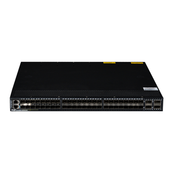
- Page 6 Front Panel Figure 1-2 Front Panel of the RG-S6220-48XS4QXS V1.XX ① Switch status indicator ⑦ 40G QSFP+ port status indicator Notes: ② PWR1 status indicator ⑧ 10/100/1000Base-T RCMI Ethernet port ③ PWR2 status indicator ⑨ Console ④RCMI management interface ⑩ 10G SFP+ port ⑪...
- Page 7 The asset management label is at the lower-right corner of the switch back panel. The label is movable and can be withdrawn from the device. Users can mark the information such as asset name, category, code and registration date on the label which helps to improve asset management rate and efficiency. Figure 1-4 Asset Management Label of the RG-S6220-48XS4QXS V1.XX External Interface The RG-S6220-48XS4QXS V1.XX provides the following interfaces:...
- Page 8 1) One of the modules of the system fails. 2) The internal temperature exceeds the warning Solid red working temperature, and the switching service resets. Blinking green. The system is initializing. Solid green The system is working normally. Solid yellow The temperature gets to the warning threshold.
- Page 9 The port is not linked up. 65F-68F (1 x 40G Solid green Port 40G is linked up. mode) Blinking green. Port 40G is transceiving data. Power Supply The RG-S6220 series switches support power supply the RG-M6220-AC460E-F. The smart power supply module supports power management, and the host can read input power, input current, and temperature in real time.
- Page 10 Frequency: 50 Hz to 60 Hz Rated current: 5.29A-2.2A Power Less than 180 W Consumption Refer to Appendix B Optical Module The supported modules update at any time, contact Ruijie Networks for details. SFP+ Port Supported QSFP+ Port Supported FC Port Unsupported...
- Page 11 The power supply system: Provides two power supply slots, which support 1+1 power supply redundancy. It is recommended users configure power supply redundancy. The heat dissipation system: Provides three power supply slots, which support 2+1 fan redundancy. It is recommended users configure all fans redundancy.
- Page 12 ① Power supply module slot ④ Grounding pole Notes: ② Fan module slot ⑤ Asset management label ③ USB2.0 interface Asset management label The asset management label is at the lower-right corner of the switch back panel. The label is movable and can be withdrawn from the device.
- Page 13 1) One of the modules of the system fails. 2) The internal temperature exceeds the warning Solid red working temperature, and the switching service resets. Blinking green. The system is initializing. Solid green The system is working normally. Solid yellow The temperature gets to the warning threshold.
- Page 14 The RG-S6220-48XS4QXS V2.XX series switches support power supply 1+1 redundancy. To improve the stability and reliability of the entire system, it is recommended to configure power supply module 1+1 redundancy. When the two power supply modules work normally, the switch is in the status of current sharing. It requires at least one power supply module to work normally.
- Page 15 Rated current: 5.29 A Power Less than 450 W Consumption Refer to Appendix A and Appendix B Optical Module The supported modules update at any time, contact Ruijie Networks for details. SFP+ Port Unsupported QSFP+ Port Supported FC Port Unsupported...
- Page 16 Front Panel Figure 1-12 Front Panel of the RG-S6220-48XT4QXS ① Switch status indicator ⑦ 40G QSFP+ port status indicator Notes: ② PWR1 status indicator ⑧ 10/100/1000Base-T RCMI Ethernet port ③ PWR2 status indicator ⑨ Console ④RCMI management interface ⑩ 10GBASE-T RJ45 interface ⑪...
- Page 17 External Interface The RG-S6220-48XT4QXS provides the following interfaces: Universal serial bus (USB) port: This port can connect with USB memory to save logs, host versions, warnings and other diagnostic messages. Therefore, it is more convenient to upgrade the software version of the switch on line and save the log information.
- Page 18 Solid yellow The temperature gets to the warning threshold. The power supply module is not in the position. The power supply temperature exceeds the normal Solid yellow working temperature. Power module 1 PWR1 indicator The power supply module fails or it is not connected Solid red with the AC power cord.
- Page 19 It requires at least one power supply module to work normally. Baffles need to be installed in the empty power supply module slots to ensure ventilation and heat dissipation and avoid dusts. Heat Dissipation The working temperature of the RG-S6220-48XT4QXS switches is 0-45℃, and the heat dissipation design needs to ensure the stability, safety and maintainability in such temperature.
- Page 20 Less than 260 W (including the dual-extension module) Consumption Refer to Appendix B Optical Module The supported modules update at any time, contact Ruijie Networks for details. SFP+ Port Supported QSFP+ Port Supported (Note: Support QSFP+ port through the extension module M6220-02QXS)
- Page 21 Front Panel Figure 1-8 Front Panel of the RG-S6220-24XS ① Switch status indicator ⑦ 10/100/1000Base-T RCMI Ethernet port Notes: ② PWR1status indicator ⑧ Console ③ PWR2status indicator ⑨ 10G SFP+ port ④RCMI management interface ⑩ Extension module Slot 1 ⑪ Extension module Slot 2 indicator ⑤...
- Page 22 The asset management label is at the lower-right corner of the switch back panel. The label is movable and can be withdrawn from the device. Users can mark the information such as asset name, category, code and registration date on the label which helps to improve asset management rate and efficiency. Figure 1-10 Asset management label of the RG-S6220-24XS External Interface The RG-S6220-24XS provides the following interfaces:...
- Page 23 Blinking green. The system is initializing. Solid green The system is working normally. Solid yellow The temperature gets to the warning threshold. The power supply module is not in the position. The power supply temperature exceeds the normal Solid yellow Power module 1 working temperature.
- Page 24 The working temperature of the RG-S6220-24XS switches is from 0℃ to 50℃, and the heat dissipation design needs to ensure the stability, safety and maintainability in such temperature. The RG-S6220 series switches adopt fan ventilation and forced convection to ensure the device can work normally in specified environment. Dust the device every three months to avoid blocking the ventilation openings.
- Page 25 Applicable RG-S6220-24XS Model Port Provide 12 10G SFP+ ports. Refer to Appendix B Transmission Medium The supported modules update at any time, contact Ruijie Networks for details. Hot plugging. Unsupported Power Less than 30 W Consumption GB9254-2008 Class A GB4943-2011 Working 0°...
- Page 26 The 10G Ethernet port of the M6220-12XS supports DAC, and the QSFP+ port supports DAC one meter, three meters and five meters, respectively. For a detailed model and specification, refer to Appendix B. 1.5.2 M6220-02QXS Module Appearance Figure 1-22 Appearance of the M6220-02QXS ①...
- Page 27 Applicable RG-S6220-24XS Model Port Provide two 40G QSFP+ ports Refer to Appendix B Transmission Medium The supported modules update at any time, contact Ruijie Networks for details. Hot plugging. Unsupported Power Less than 20 W Consumption GB9254-2008 ClassA GB4943-2011 Working 0°...
- Page 28 Provide eight 2/4/8G self-adaption FC ports. Port Provide eight 10G/1G SFP+ ports. Refer to Appendix B Transmission Medium The supported modules update at any time, contact with Ruijie Networks for details. Hot plugging. Unsupported Power Less than 20 W Consumption...
- Page 29 The ports of the M6220-08FC support FC and Ethernet mode. Please configure the required working mode according to Configuration Guide of Ruijie Networks. The M6220-08FC ports working in Ethernet mode support 10G SFP+ module and1G SFP module. But the10G SFP+ module cannot function as the 1G SFP module.
- Page 30 Model M6220-08XT Applicable RG-S6220-24XS Model Port Provide eight RJ45 ports, which support 10GBASE-T/1000BASE-T/100BASE-TX. 10Gbase-T, 1000Base-T, 100Base-TX Transmission Medium For detailed cable specification and cabling guide, please refer to Appendix A. Hot plugging. Unsupported Power Less than 45 W Consumption GB9254-2008 Class A GB4943-2011 Working 0°...
- Page 31 The fan is not powered up. Status Indicator Status Solid green The fan is working normally. Solid red The fan fails or stops. Specifications Fan Model M6220-FAN-F Ventilation 30 CFM Indication Max Speed 25000 RPM Power 15 W Consumption Weight Net weight: 0.25 kg Dimensions 166 x 55.7 x 41.2 (L x W x H, mm)
- Page 32 Specifications Fan Model M6220- FAN II-F Ventilation 20 CFM Indication Max Speed 18000 RPM Power Consumption Weight Net weight: 0.25 kg Dimensions 166 x 55.7 x 41.2 (L x W x H, mm) 1.5.7 M6220-AC460E-F The M6220-AC460E-F is the power supply module of the RG-S6220 series and provides power supply for the RG-S6220 series.
-
Page 33: Preparation Before Installation
2 Preparation before Installation 2.1 Safety Precautions To avoid body injury and device damage, please carefully read the safety precautions before you install the RG-S6220. The following safety precautions do not cover all possible dangers. 2.1.1 Installation Safety Keep the chassis clean and dust-free. ... -
Page 34: Laser Safety
Any nonstandard and inaccurate electrical operation can cause accidents such as fires or electrical attacks, thus causing severe , or even fatal damages to human bodies and the devices. Direct or indirect touch through a wet object on high-voltage and mains supply can bring a fatal danger. 2.1.4 Electrostatic Discharge Damage Precautions The RG-S6220 designing gives a great consideration to prevent electrostatic discharge damage and adopts multiple measures. -
Page 35: Ventilation Requirements
Install the switch in an open cabinet as much as possible. If you install the switch inside a closed cabinet, be sure that the cabinet has a good ventilation and heat dissipation system. Be sure that the cabinet is firm enough to bear the weight of the RG-S6220 and its installation accessories. ... -
Page 36: System Grounding Requirements
Dust particles (diameter ≥5μm) ≤3×10 Apart from dust, the salt, acid and sulfide in the air in the equipment room must also meet strict requirements; as such poisonous substances may accelerate the corrosion of the metal and the aging of some parts. The equipment room should be protected from the intrusion of harmful gases (for example, SO S, NO and Cl... -
Page 37: Emi Consideration
2.2.6 EMI Consideration Various interference sources, from either outside or inside the device or application system, affect the system in the conductive ways such as capacitive coupling, inductive coupling, and electromagnetic radiation. There are two types of electromagnetic interferences: radiated interference and conducted interference, depending on the type of the propagation path. -
Page 38: Unpacking And Checking
RG-S6220 series is not shipped with a tool kit. You need to prepare a tool kit by yourself. 2.5 Unpacking and Checking Goods Checklist Chassis, Yellow/green grounding cables; Quick installation guide; Packing list, Pouched Chassis Carton documents Module Carton Various modules; Packing list; Quick installation guide A normal delivery should contain the above mentioned items, which may differ from the actual delivery, depending on purchase contracts. -
Page 39: Product Installation
3 Product Installation RG-S6220 series Ethernet switch must be used and fixed in the room. Make sure you have carefully read part 2, and be sure that the requirements set forth in part 2 have been met. 3.1 Installation Procedure Assemble RG-S6220 before installation Install the cabinet Mount the device into the cabinet... -
Page 40: Cabinet Installation
The related network cables have already been deployed at the installation location. 3.3 Cabinet Installation Precautions When you install the cabinet, pay attention to the following requirements: All expansion bolts for fastening the cabinet base to the ground should be installed and tightened in sequence from bottom up (large plain washer, spring washer, and nut), and the installation holes on the base and the expansion bolts should be well aligned. - Page 41 should reserve space of at least 10mm between the front panel of the equipment and that of the cabinet after installation. Before mounting into a cabinet, you need to make sure the following conditions are met: Fasten the cabinet. ...
-
Page 42: Installing And Removing A Fan Module
The mounting brackets are located at the four of the six screw holes at both sides on the back panel of the host. Distinguish the left and the right rear brackets according to the marked directions. The rear brackets provided are only applicable for cabinets with depth of 800mm - 1200mm. Mounting the Switch to a Workbench In some cases, users do not have the 19-inch standard cabinet. - Page 43 Wear anti-static gloves before the following operations. Installing an M6220-FAN-F/M6220-FAN II-F Fan Module Take out a new fan module from the fan module box. Hold the handle at the end of the fan module. Insert the fan module to the chassis slowly along the guide rail until it is fully seated, and make sure that it is in good contact with the slot.
- Page 44 The M6220 series extension modules do not support the hot-plugging. Power off the switch before extension module installation or replacement. Wear anti-static gloves before the following operations. Installing an M6220 Series Extension Module Take off the baffle in the extension slot on the front panel of a RG-S6220 series switch. Pinch the captive screws on the extension module, and leave the angle between the ejector and the front panel of the module to the maximum.
- Page 45 Figure 3-7 Removing an M6220 series extension module Withdraw the extension module uprightly and slowly. Do not hold the edges of the printed plate or press the components on the printed plate. Install a baffle on the location where an extension module is removed to ensure normal ventilation and dissipation and avoid dust in the chassis.
- Page 46 If it is difficult or even impossible to insert the module, pull out the module, make sure the extension module and guide rail are well aligned, and then insert the module again. Removing a RG-M6220-AC460E-F Power Module Press the plug of the power module, Hold on to the module handle with one hand to pull out part of the module, hold the bottom of it with the other hand, and pull out the power module uprightly and slowly..
-
Page 47: Connecting The External Interface Cables
During the device installation, always make the ground connected first and disconnected last. The cross-sectional area of protective earthing conductor should be at least 2.5 mm2 (12 AWG). 3.8 Connecting the Cables of the Management Serial Ports Simple Connection Steps Connect the RJ45 connector to the Console interface of the management engine module with shipped console cable , and connect the DB9 connector to the NM or control terminal. - Page 48 For the power cables, you should bind them closely along the chassis downward in a straight line wherever possible. 3.11 Installation Verification Verifying the Cabinet Verify if the external power supply matches the distribution panel of the cabinet. After equipment is installed, verify if the front/back cabinet doors can be closed.
-
Page 49: System Debugging
4 System Debugging 4.1 Establishing the Configuration Environment Establishing the Configuration Environment Connect the PC to the console port of the switch through the console cable, as shown in Figure 4-1. Figure 4-1 Schematic diagram of the configuration environment Connecting the Console Cable Connect one end of the DB-9 jack of the console cable to the serial port of the PC. - Page 50 Figure 4-2 Enter the name of the new connection and click OK. A window appears as shown in Figure 4-3. In the column of Connect Using field, select the serial port you want to use. Figure 4-3 After the serial port is selected. click OK. The Serial Port Parameter Setting window is displayed, as shown in Figure 4-4.
-
Page 51: Power-On Startup
After the serial port parameters are set, click OK to enter hyper terminal window. 4.2 Power-on Startup Checking before Power-on Check if the switch is fully grounded. Check if the fan module and the power module are correctly installed. ... -
Page 52: Monitoring And Maintenance
5 Monitoring and Maintenance 5.1 Monitoring Indicator When the RG-S6220 is running, users can monitor the status of host and each module by inspecting corresponding indicators. When the indicator of the master CM is red, it means the system has a fault, in which case you can determine and eliminate the fault by viewing with the management software. - Page 53 The built-in lithium batteries can support the real time clock of the RG-S6220 series switches without external power supply. Please contact the technical support representatives of Ruijie Networks for replacing lithium batteries. Technical staff of Ruijie Networks will replace the battery of the same model.
-
Page 54: Troubleshooting
Check the indicators on the device and the modules Check the connection of the serial ports and its parameters Check the connection of the fibers or cables of various ports Contact Technical Support of Ruijie Networks for hardware problems - 51 -... -
Page 55: Common Troubleshooting Procedures
6.2 Common Troubleshooting Procedures Fault 1: The system login password is lost [Fault Description] The system login password of the switch is forgotten or lost, and so it is not possible to configure the data. [Troubleshooting] Please contact Ruijie Customer Service Department for technical support. Fault 2: The AC power module does not work The indicator on the front panel of host is OFF. - Page 56 Such a problem is related to the settings of the serial port. Check if the settings of such parameters as the baud rate match those in RG-S6220 series Software Configuration Guide. Fault 6: The newly-inserted service card module fails to be powered on. [Fault Description] The system is running, yet all indicators on the panel of the newly-inserted expansion module are OFF, and the port is faulty.
-
Page 57: Appendix A Connectors And Connection Media
Appendix A Connectors and Connection Media 10GBASE-T/1000BASE-T/100BASE-TX Port 10GBASE-T/1000BASE-T/100BASE-TX is a port that supports self-adaptation of three rates, and automatic MDI/MDIX Crossover at these three rates. 10GBASE-T complies with IEEE 802.3an standard, and the supported cables and cabling distances are listed in the following table. - Page 58 Figure A-1 Four twisted pairs of the 1000BASE-T In addition to the above cables, the 100BASE-TX can use up to 100m of 100-ohm CAT5. Figure A-2 shows the definition of pin signal concerning the 100BASE-TX: Figure A-2 Definition of pin signal concerning the 100BASE-TX Socket Plug Input Receive Data+...
-
Page 59: Appendix B Mini-Gbic, 10G, 40G And Fc Module
Appendix B Mini-GBIC, 10G, 40G and FC Module We provide 1000M SFP modules (Mini-GBIC modules), 10G SFP+ modules, 40G QSFP+ modules and FC modules. according to the types of interfaces of the switch modules. You can select modules to suit your specific needs. The following models and technical specifications of some 1000M SFP modules, 10G SFP+ modules, 40G QSFP+ modules and FC modules are listed for your reference. - Page 60 The existing 10G SFP+ optical modules: Intensity of Intensity of Wave Optical Modular Transmitted Received Light Core Size Cabling Model length Fiber Bandwidth (μm) distanc Light (dbm) (dbm) (nm) Type (MHz·km) 62.5 XG-SFP-SR-MM850 -7.5 2000 300m interface) XG-SFP-LR-SM1310 1310 10km -8.2 -10.3 interface)
- Page 61 The existing 40G QSFP+ copper modules: Copper Support Module Connector Conductor Wire Model Cable Data Rate(Gb/s) Type Type Diameter (AWG) Length (m) (Yes/No) 4lanes x 40G-QSFP-STACK3 Passive QSFP+ 10.3125 (Perlane) Models and technical specifications of the FC module The existing FC optical modules: Intensity of Intensity of Wavel...
-
Page 62: Appendix C Lightning Protection
Appendix C Lightning Protection Installing AC Power Arrester (lightning protection cable row) The external lightning protection cable row should be used on the AC power port to prevent the switch from being struck by lightning when the AC power cable is introduced from the outdoor and directly connected to the power port of the switch. - Page 63 Installing the Ethernet Port Arrester During the switch usage, the Ethernet port arrester should be connected to the switch to prevent the switch damage by lightning before the outdoor network cable connects to the switch . Tools: Cross or straight screwdriver, Multimeter, Diagonal pliers Installation Steps: Tear one side of the protection paper for the double-sided adhesive tape and paste the tape to the framework of the Ethernet port arrester.
- Page 64 You should pay attention to the following conditions during the actual installation to avoid influencing the performance of the Ethernet port arrester: Reversed direction of the arrester installation. You shall connect the external network cable to the “IN” end and connect the switch Ethernet port to the “OUT”...
-
Page 65: Appendix D Cabling Recommendations In Installation
Appendix D Cabling Recommendations in Installation When the switches are installed in standard 19-inch cabinets, the cables are tied in the binding rack on the cabinet by the cable management bracket, and top cabling or bottom cabling is adopted according to the actual situation in the equipment room. - Page 66 Cables of different types (such as power cords, signal cables, and grounding cables) should be separated in cabling and bundling and no mixed bundling is allowed. When they are close, crossover cabling can be adopted. In the case of parallel cabling, power cords and signal cables should maintain a distance not less than 30 mm. ...
- Page 67 Cables not to be assembled or remaining parts of cables should be folded and placed in a proper position of the cabinet or cabling slot. The proper position indicates a position that will not affect device running or cause device damage or cable damage during commissioning.
- Page 68 Figure D-4 Cable fastening The hard power cable should be fastened at the terminal connection area to prevent stress on terminal connection and cable. Do not use self-tapping screws to fasten terminals. Power cables of the same type and in the same cabling direction should be bundled up into cable bunches, with cables in cable bunches clean and straight.
-
Page 69: Appendix E Site Selection
Appendix E Site Selection The machine room should be at least 5km away from the heavy pollution source such as the smelter, coal mine and thermal power plant, 3.7km away from the medium pollution source such as the chemical industry, rubber industry and electroplating industry, and 2km away from the light pollution source such as the food manufacturer and leather plant.
Need help?
Do you have a question about the RG-S6220-48XS4QXSV1 and is the answer not in the manual?
Questions and answers