Table of Contents
Advertisement
Quick Links
Advertisement
Table of Contents

Related Manuals for Ruijie Networks RG-S6200 Series


Summary of Contents for Ruijie Networks RG-S6200 Series
- Page 1 Installation Manual RG-S6200 Series Switch...
-
Page 2: Copyright Statement
Disclaimer The information contained in this manual may be modified without notification. Ruijie Networks has tried its best to maintain the accuracy and reliability of this manual on the website. Ruijie Networks takes no responsibility for the... - Page 3 Documentation CD-ROM: The documentation of Ruijie Networks switches is stored in the CD-ROM package, which is provided to you together with the product you purchase. The CD-ROM is updated frequently, and may be more current than the printed documents.
- Page 4 Customer service center of Ruijie Networks, which can provide all customers with needed technical assistance for products, technologies and solutions. The customer service center provides responsive technical support for your product installation problems, software configuration problems, and other network performance problems.
-
Page 5: Chapter 1 Product Overview
The RG-S6200 series switches are the next generation high-density full 10G layer3 IPv6 switches introduced by Ruijie Networks. They are mainly applicable to the data center and positioned at the EoR (End of Row), as well as at the ToR (Top of Rack) to provide the convergence access for the servers with 10G interfaces and intranet. - Page 6 Ethernet 10G: XG-SFP-SR-MM850 XG-SFP-LR-SM1310 Note: the supported module type may change at any time. For the detailed change information, consult the Ruijie Networks. Extended Module M6200-16XS Type Note: the supported module type may change at any time. For the detailed change information, consult the Ruijie Networks.
-
Page 7: Product Appearance
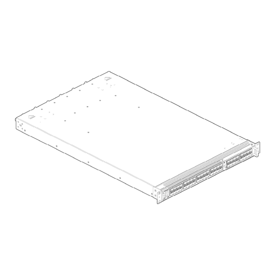
Weight 13.5Kg 1.3 RG-S6200-48XS Series Switches 1.3.1 Product Appearance The front panel of the RG-S6200 switch provides thirty two 32 10G ports, one console port, one 10/100/1000Base-T Ethernet port, and one USB2.0 port. The backpanel provides two power slots and four dual fan slots. Figure1-1 shows the appearance of the M6200-16XS extension module. -
Page 8: Power Supply System
3. PWR2 2 status indicator 4. MGMT management interface indicator 5. Fan indicator 6. USB2.0 port 7. 10/100/1000Base-T MGMT Ethernet port 8. Console port 9. 10G SFP+ port 10. Port status indicator 11. Extension slot 1.3.1.2 Ports on the Backpanel The backpanel of the RG-S6200 switch provides the slots for the power supply modules and fan modules. - Page 9 The power supply module of the RG-S6200 series switch has two modes of air direction: -F and –R. The two modes of power supply can not be mixed. It is strongly recommended that user pay attention to the power supply selection during installation.
- Page 10 Figure 1-6 Flow scheme of –R heat dissipation 1.4 Indicators on RG-S6200 Series Switches Table 1-4 Indicators for the RG-S6200 Indicator Definition Status Meaning Status indicator Indicates the system The system has no power supply. status. Blinking green The switch is being initialized with 3HZ blinking frequency.
- Page 11 B. Data is transmitted on the port. Port link is not up. 1.5 Module Types Supported by the RG-S6200Series Switches The RG-S6200 series switch supports the following modules: M6200-16XS extension module, which is used to support the extension for the RG-6200 series switch.
-
Page 12: Applicable Models
Multiple extensible SFP optical modules IEEE 802.3, SFF-8431/8432 and SFP MSA-compliant 1.5.1.3 Applicable Models M6200-16XS is applicable for RG-S6200 series and other subsequential switches supporting this module, including: RG-S6200-48XS 1.5.1.4 Indicator Description M6200-16XS comes with 16 SFP+ port indicators, which are defined as below:... - Page 13 Figure1-8 RG-M6200-AC650I-F(R) power supply module 1. Power supply status indicator 2. Power plug 1.5.2.2 Features RG-M6200-AC650I-F(R) provides the power supply with rated voltage of 12V for the RG-S6200 series switch. Features are shown as below: Support the 1+1 redundancy.
- Page 14 Automatically adjust the rotation speed of the fan according to the temperature. Support the fan alarm function. Support the hot-plugging of the fan tray. Support the fan type identification. 1.5.3.3 Applicable Models M6200-FAN-F(R) is applicable for RG-S6200 series and other subsequential switches supporting this module, including:...
- Page 15 RG-S6200-48XS 1.5.3.4 Indicator Description M6200-FAN-F(R) comes with a fan status indicator, which is defined as below: Automatically adjust the rotation speed of the fan according to the temperature. Solid green: The fan works normally. Solid yellow: The module type conflicts with the other fan module types of the system. ...
-
Page 16: Chapter 2 Preparation Before Installation
Chapter 2 Preparation before Installation 2.1 Safety Suggestions To avoid personal injury and equipment damage, please carefully read the safety suggestions before you install the RG-S6200 series. The following safety suggestions do not cover all possible dangers. 2.1.1 Safety Precautions for Installing the System ... -
Page 17: Installation Site Requirements
Do not stare into any optical port under any circumstances, as this may cause permanent damage to your eyes. 2.2 Installation Site Requirements The RG-S6200 series must be used indoors. To ensure the normal working and a prolonged durable life of the equipment, the installation site must meet the following requirements. -
Page 18: Cleanness Requirements
Temperature Relative Humidity 0ºC-50ºC 10%-90% The ambient temperature and humidity are measured at the point that is 1.5 m above the floor and 0.4 m before the equipment when there is no protective plate in front or back of the equipment rack. 2.2.3 Cleanness Requirements Dust poses a severe threat to the running of the equipment. -
Page 19: System Grounding Requirements
2.3 System Grounding Requirements A good grounding system is the basis for the stable and reliable operation of the RG-S6200 series. It is the chief condition to prevent lightning stroke and resist interference. Please carefully check the grounding conditions on the installation site according to the grounding requirements, and perform grounding operations properly as required. -
Page 20: Emi Consideration
on the the cabinet, work station, or the equipment room's wall through line buckles and screws. In applications, the AC first enters the lightning line bank and then the switch. The lightning line banks are not provided and should be purchased by users as required. For the usage of lightning line banks, refer to their related manuals. - Page 21 The RG-S6200 series are not provided with a tool kit. Please prepare tools on your own.
-
Page 22: Chapter 3 Product Installation
Chapter 3 Product Installation Please ensure that you have carefully read Chapter 2. Make sure that the requirements set forth in Chapter 2 have been met. 3.1 Installation Procedure 3.2 Confirmations before Installation Before installation, please confirm the following points:... - Page 23 During the installation, fasten the pallet onto the rack and then place the front panel of the switch to the pallet. Fix the switch to the pallet and rack with screws. Because the depth and weight of the RG-S6200 series switch are 690mm and 13.5Kg, the switch can be fastened with the pallet first, and then fastened onto the rack of...
- Page 27 Because the depth and weight of the RG-S6200 series switch are 690mm and 13.5Kg, the switch must be fastened with the pallet first, and then fastened onto the rack of the cabinet. 3.3.3 Mounting the Switch to the Desktop In several cases, users do not have the 19-inch standard cabinets. In this case, the most frequent method is to mount the switch to a clean workstation.
-
Page 28: Module Installation
3.4 Module Installation 3.4.1 M6200-16XS Extension Module Installation 3.4.1.1 Installing the Extension Module When installing the extension module, note that: Power off the switch before installing the extension module because it does not support the hot-plugging. Wear the anti-static gloves, and then remove the blank panel of the extended port of the front panel of the RG-S6200. -
Page 29: Removing The Power Module
Figure 2-2 Installing the power module Insert the power module smoothly. Please pay attention to the direction of the power panel to avoid the wrong insertion. If the position is not proper, you must withdraw the inserted module and then re-insert it. 3.4.2.2 Removing the Power Module The process of removing the power module is reverse to the installation. -
Page 30: Checking After Installation
Figure 2-4 Installing the fan module Insert the fan module in a smooth manner. Pay attention to the direction of the fan panel to avoid wrong insertion. If the position is not proper, you must withdraw the inserted module and re-insert it. Step 3: Tighten the captive screws with a screwdriver to fix the fan module in the switch chassis. - Page 31 Before checking the installation, switch off the power supply so as to avoid any personal injury or damage to the component due to connection errors. Check that the ground line is connected. Check that the cables and power input cables are correctly connected. ...
-
Page 32: Chapter 4 System Debugging
Chapter 4 System Debugging 4.1 Establishing the Configuration Environment 4.1.1 Establishing the Configuration Environment Connect the PC to the console port of the switch through the console cable, as shown in Figure 4-1. Figure 4-1 Schematic diagram of the configuration environment 4.1.2 Connecting the Console Cable Step 1: Connect one end of the DB-9 jack of the console cable to the serial port of the PC. - Page 33 The console cable is correctly connected; the terminal (can be a PC) used for configuration is already started; the parameters are already configured. 4.2.2 Checking after Power-on (Recommended) After power-on, you are recommended to perform the following checks to ensure the normal operation of follow-up configurations.
-
Page 34: Chapter 5 Maintenance And Troubleshooting
Chapter 5 Maintenance and Troubleshooting 5.1 General Troubleshooting Procedure 5.2 Troubleshooting Common Faults Symptom Possible Causes Solution Forgetting management Please contact Ruijie Networks interface login password Customer Service Department technical support. The status indicator is not on after The power supply module does Check whether the power socket at the the switch is started. - Page 35 Symptom Possible Causes Solution normal service exchanges. Check in time the working environment of the switch, clean the dust on the cabinet and reinforce the refrigeration effect. The FAN indicator on the front panel The fan number inserted is less Check the fan number inserted and the is red.
-
Page 36: Appendix A: Connectors And Connection Media
Appendix A: Connectors and Connection Media 1. 1000BASE-T/100BASE-TX/10BASE-T Ports The 1000BASE-T/100BASE-TX/10BASE-T is a port that supports adaptation of three rates, and automatic MDI/MDIX Crossover at these three rates. 1000The 1000BASE-T complies with IEEE 802.3ab, and uses the cable of 100-ohm Category-5 or Supper Category-5 UTP or STP, which can be up to 100 m. 1000The 1000BASE-T port uses four pairs of wires for transmission, all of which must be connected. - Page 37 2. Optical Fiber Connection For the optical fiber ports, select single-mode or multiple-mode optical fibers for connection according to the fiber module connected. The connection schematic diagram is shown in Figure A-4: Figure A-4 Schematic diagram for optical fiber connection Switch Switch...
-
Page 38: Appendix B Mini-Gbic Modules
Appendix B Mini-GBIC Modules We provide appropriate 1000M SFP modules (Mini-GBIC modules) according to the types of interfaces of the switch modules. You can select the SFP module to suit your specific needs. The following models and technical specifications of some 1000M SFP modules are listed for your reference. Models and Technical Specifications of the Mini-GBIC (SFP) Module Table B-1 Models and technical specifications of the SFP module Modular... - Page 39 CAT 5 Mini-GBIC-GT 100m For the optical module with transmission distance exceeding 40km and higher, one on-line optical attenuator should be added on the link to avoid the overload of the optical receiver when short single-mode optical fibers are used.
-
Page 40: Appendix C Sfp+ Modules
Appendix C SFP+ Modules We provide appropriate 10G SFP+ modules modules according to the types of interfaces of the switch modules. You can select the SFP+ module to suit your specific needs. The following models and technical specifications of some 10G SFP+ modules are listed for your reference.
Need help?
Do you have a question about the RG-S6200 Series and is the answer not in the manual?
Questions and answers