Table of Contents
Advertisement
Quick Links
Advertisement
Table of Contents

Related Manuals for Ruijie Networks RG-S2910C-XS-P Series


Summary of Contents for Ruijie Networks RG-S2910C-XS-P Series
- Page 1 RG-S2910C-XS-P Series Switch Hardware Installation and Reference Guide V1.00...
-
Page 2: Copyright Statement
This document is provided “as is”. The contents of this document are subject to change without any notice. Please obtain the latest information through the Ruijie Networks website. Ruijie Networks endeavors to ensure content accuracy and will not shoulder any responsibility for losses and damages caused due to content omissions, inaccuracies or errors. -
Page 3: Obtaining Technical Assistance
It is intended for the users who have some experience in installing and maintaining network hardware. At the same time, it is assumed that the users are already familiar with the related terms and concepts. Obtaining Technical Assistance Ruijie Networks website: http://www.ruijienetworks.com Online customer services: http://webchat.ruijie.com.cn... -
Page 4: Product Overview
Product Overview The RG-2910C-XS-P series is a multi-service 2-layer switch designed by Ruijie with high performance and security. It is mostly applied at the access layer of large-sized networks to provide line-speed exchanging and complete QoS services, and ensure low-delay transmission of key data by applying service-specific traffic classification rules. The RG-2910C-XS-P series provides flexible medium interfaces and can meet the connection requirements of different media in network constructions. - Page 5 Mini-GBIC-LH40 Mini-GBIC-ZX50 Mini-GBIC-ZX80 Mini-GBIC-ZX100 GE-SFP-LX20-SM1310-BIDI GE-SFP-LX20-SM1550-BIDI GE-SFP-LH40-SM1310-BIDI GE-SFP-LH40-SM1550-BIDI Ethernet 10G 10G BASE-SR 10G BASE-LR 10G BASE-ER 1000Base-T Mini-GBIC-GT The supported module type may change at any time. Contact Ruijie Networks for details. M2910-01XT Expansion Module M2910-01XS 100Base-X SFP Port 1000Base-X SFP+ Port See Appendix C...
- Page 6 HVDC Rated voltage range: 192 V to 290V Rated current range: 2.5 A to 3.5 A RG-PA1150P-F Rated voltage range: 100 V to 240 V Frequency range: 50/60 Hz Rated current: 10 A HVDC Rated voltage range: 192 V to 290 V Rated current: 10 A ...
-
Page 7: Product Appearance
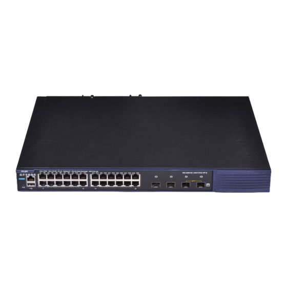
Weight 5.8 kg (with package) The RG-S2910C-XS-P series switch is a class A product. In a domestic environment, this product may cause radio interference in which case the user may be required to take adequate measures. Product Appearance The front panel of the RG-S2910C-24GT2XS-HP-E Ethernet switch provides twenty-four 10/100/1000Base-T Ethernet ports, two GE SFP fiber/copper combo ports, two 10G SFP+ fiber ports and one Console port. -
Page 8: Back Panel
Note: System status LED Fiber port status LED Expansion module 1 status LED PoE mode switch-over button Expansion module 2 status LED Console port Power module 1 status LED USB port Power module 2 status LED 10/100/1000Base-T auto-sensing Ethernet port PoE status LED 100/1000Base-X SFP port Copper port status LED... - Page 9 100 V to 240 V Rated Voltage Range 240 V 50/60 Hz 90 V to 264 V Maximum Voltage 192 V to 290 V Range 50/60 Hz Single power supply: 370W PoE Power Dual power supplies: 740W Hot Swapping Supported Redundant Power Supplies...
- Page 10 RG-S2910C-48GT2XS-HP-E Rated Voltage Range -72 V to -32 V Single power supply: 370 W PoE Power Dual power supplies: 740 W Hot Swapping Supported Redundant Power Supplies 54 V: -66 V to -58 V Over-Voltage Protection 12 V: 13.2 V to 15.6 V 54V: 7.8 A to 10 A Over-Current Protection...
- Page 11 50/60 Hz 90 V to 264 V 192 V to 290 V Maximum Voltage Range 50/60 Hz Single power supply: 740 W PoE Power Dual power supplies: 1480 W Hot Swapping Supported Redundant Power Supplies 54V: -60 V to -57 V Over-Voltage Protection 12V: 14 V to 16 V...
-
Page 12: Heat Dissipation
Heat Dissipation The RG-S2910C-24GT2XS-HP-E adopts turbine fans for heat dissipation, thereby ensuring normal function of the device in the specified environment. 10 cm distance space should be reserved at both sides and the back plane of the cabinet to allow air circulation. It is recommended to clean the device once every 3 months to avoid dust from blocking vents. Figure 1-4 shows the flow scheme of heat dissipation. - Page 13 Temperature warning. Solid yellow Check the working environment of the switch immediately. The switch is faulty. Solid red For details, see the section “Troubleshooting Common Faults”. There is no expansion module or the expansion Expansion module module is not correctly installed. M1/M2 status LED Solid green...
-
Page 14: Technical Specifications
The port is not connected. Solid green The port is connected at 1000 Mbps. The port is receiving or transmitting traffic at 1000 1000Mbps SFP port Blinking green 23F-24F Mbps. status LED Solid yellow The port is connected at 100 Mbps. The port is receiving or transmitting traffic at 100 Blinking yellow Mbps. - Page 15 Mini-GBIC-ZX80 Mini-GBIC-ZX100 GE-SFP-LX20-SM1310-BIDI GE-SFP-LX20-SM1550-BIDI GE-SFP-LH40-SM1310-BIDI GE-SFP-LH40-SM1550-BIDI Ethernet 10G 10G BASE-SR 10G BASE-LR 10G BASE-ER 1000Base-T Mini-GBIC-GT The supported module type may change at any time. Contact Ruijie Networks for details. M2910-01XT Expansion Module M2910-01XS 100Base-X SFP Port 1000Base-X SFP+ Port See Appendix C RPS Type...
- Page 16 Rated current range: 2.5 A to 3.5 A RG-RG-PA1150P-F Rated voltage range: 100 V to 240 V Frequency range: 50/60 Hz Rated current: 10 A HVDC Rated voltage range: 192 V to 290V Rated current: 10A M5000E-DC500P (DC) Rated voltage range: -72 V to -36 V Rated current:16.5 A Supported on all RJ45 ports...
- Page 17 The RG-S2910C-XS-P series switch is a class A product. In a domestic environment, this product may cause radio interference in which case the user may be required to take adequate measures. Product Appearance The front panel of the RG-S2910C-48GT2XS-HP-E Ethernet switch provides forty-eight 10/100/1000Base-T Ethernet ports, two GE SFP fiber/copper combo ports, two 10G SFP+ fiber ports and one Console port.
- Page 18 Note: System status LED 8. Fiber port status LED 2. Expansion module 1 status LED 9. PoE mode switch-over button 3. Expansion module 2 status LED 10. Console port 4. Power module 1 status LED 11. USB port 5. Power module 2 status LED 12.
- Page 19 Figure 1-8 Flow Scheme of Heat Dissipation LEDs Panel Identification State Meaning System status LED Status The switch is not receiving power. Initialization in progress. Blinking green Continuous blinking indicates errors. Solid green The switch is operational. Temperature warning. Solid yellow Check the working environment of the switch immediately.
- Page 20 The switch is faulty. Solid red For details, see the section “Troubleshooting Common Faults”. There is no expansion module or the expansion module is not correctly installed. Expansion module M1/M2 status LED Solid green The expansion module is correctly installed. The power module is not in place.
- Page 21 The port is receiving or transmitting traffic at 1000 Blinking green Mbps. M2910 Expansion Modules The RG-S2910C-XS-P series switch supports M2910-01XS, M2910-01XT, M2910-02XS and M2910-02XT modules. M2910-01XT/2XT provides 1-/2-port 10GBASE-T Ethernet ports. M2910-01XS/2XS provides 1-/2-port 10G SFP+ ports and supports 10GBASE-SR/LR/LRM modes. Multiple Ruijie optical modules are available for different transmission distances.
-
Page 22: Preparation Before Installation
Preparation before Installation Safety Suggestions To avoid personal injury and equipment damage, please carefully read the safety suggestions before you install the RG-2910C-XS-P. The following safety suggestions do not cover all possible dangers. Installation Keep the chassis clean and free from any dust. ... -
Page 23: Static Discharge Damage Prevention
Any nonstandard and inaccurate electric operation may cause an accident such as fire or electrical shock, thus causing severe even fatal damages to human bodies and equipment. Direct or indirect touch through a wet object on high-voltage and mains supply may bring a fatal danger. Static Discharge Damage Prevention To prevent damage from static electricity, pay attention to the following: ... - Page 24 In an environment with low relative humidity, however, the insulating strip may dry and shrink. Static electricity may occur easily and endanger the circuit on the equipment. In an environment with high temperature, the equipment is subject to even greater harm, as its performance may degrade significantly and its useful life may be shortened in the case of long-term exposure that expedites the aging process.
- Page 25 Data within less than 30 minutes every day are considered into the one-week average and maximum.. Various interference sources, from either outside or inside the equipment or application system, affect the system in the conductive ways such as capacitive coupling, inductive coupling, and electromagnetic radiation. There are two types of electromagnetic interference: radiated interference and conducted interference, depending on the type of the transmission path.
-
Page 26: Safety Grounding
Grounding A good grounding system is the basis for the stable and reliable operation of the RG-2910C-XS-P switch. It is the chief condition to prevent lightning stroke and resist interference. Please carefully check the grounding conditions on the installation site according to the grounding requirements, and perform grounding operations properly as required. The correct connection of grounding lines guarantees the lighting and interference resistance of switches and must be performed with precision. -
Page 27: Lightning Resistance
The grounding required for EMC design includes shielding ground, filter ground, noise and interference suppression, and level reference. All the above constitute the comprehensive grounding requirements. The grounding resistance should be less than 1 ohm. The RG-2910C-XS-P back plane is reserved with one grounding pole, as shown in 0. Figure 2-1 Schematic Diagram of the RG-2910C-XS-P Grounding Lightning Resistance When the AC power cable is imported outdoors and directly connected to the power port of the switch, lightning line bank... - Page 28 Special Tools Anti-static tools Meters Multimeter The RG-2910C-XS-P switches are not provided with a tool kit. Please prepare tools on your own.
-
Page 29: Product Installation
· Product Installation Please ensure that you have carefully read the section of “Preparation before Installation”. Make sure that the requirements set forth in “Preparation before Installation” have been met. Installation Flowchart Confirmations before Installation Before installation, please confirm the following points: ... - Page 30 · Installing the RG-2910C-XS-P Precautions During installation, note the following points: Connect the power cables of different colors to the corresponding grounding posts. Ensure that the connected power cables have sound contact. Do not place heavy items on the switch. ...
-
Page 31: Mounting The Switch On The Wall
· Use the supplied M6 screws and cage nuts to securely attach the mounting brackets to the rack, as shown in Figure 3-3. Figure 0-3 Mounting the Switch on the Wall The RG-2910C-XS-P series switch can be mounted on the wall, as shown in the following figure. Attach the mounting brackets to the switch with the supplied screws, as shown in Figure 3-4. -
Page 32: Mounting The Switch On A Table
· Use the expansion screws to securely attach the mounting brackets on the wall, as shown in Figure 3-5. Figure 0-4 Attaching the switch on the Wall Mounting the Switch on a Table Attach the four rubber feet to the recessed areas on the bottom of the switch, as shown in Figure 3-6. Figure 3-6 Attaching the Rubber Feet to the Recessed Areas... -
Page 33: Checking After Installation
· Place the switch on the table, as shown in Figure 3-7. Figure 3-7 Mounting the Switch on the Table The device must be installed and operated in the place that can restrict its movement. Checking after Installation Before checking the installation, switch off the power supply so as to avoid any personal injury or damage to the component due to connection errors. -
Page 34: System Debugging
· System Debugging Establishing the Configuration Environment Establishing the Configuration Environment Connect the PC to the console port of the switch through the console cable, as shown in 0. Figure 4-1 Schematic Diagram of the Configuration Environment Connecting the Console Cable Connect one end of the DB-9 jack of the console cable to the serial port of the PC. - Page 35 · Enter the name of the new connection and click OK to display the following page. Choose the serial port used currently in the column [use when connecting]. Figure 4-3 After choosing the serial port, click OK to display the serial port parameter setting page, set the baud rate to 9600, data bit to 8, parity check to none, stop bit to 1 and flow control to none.
-
Page 36: Power-On Startup
· After setting the parameters, click OK to enter the hyper terminal page. Power-on Startup Checking before Power-on The switch is fully grounded. The power cable is correctly connected. The power supply voltage complies with the requirement of the switch. ... -
Page 37: Maintenance And Troubleshooting
Troubleshooting Common Faults Symptom Possible Causes Solution Forgetting the management Please contact Ruijie Networks Customer interface login password Service Department for technical support. The power supply module does not The status indicator is not Check whether the power socket at the supply power. - Page 38 started. The power cable is in loose contact. power cable of the switch is in good contact. Fan alarm: Check whether the fan is blocked or damaged. Temperature alarm: the switch already stops the normal service exchanges. Check in time the working environment of the switch, clean Fan alarm the dust on the cabinet and reinforce the...
- Page 39 The RPS power module in use is not of Replace the RPS power supply module with the specified type. one specified by Ruijie Networks. The RPS power indicator is The RPS power supply module is Replace the RPS power supply.
-
Page 40: Appendix A Connectors And Connection Media
Appendix A Connectors and Connection Media 1000BASE-T/100BASE-TX/10BASE-T Ports The 1000BASE-T/100BASE-TX/10BASE-T is a port that supports adaptation of three rates, and automatic MDI/MDIX Crossover at these three rates. The 1000BASE-T complies with IEEE 802.3ab, and uses the cable of 100-ohm Category-5 or Supper Category-5 UTP or STP, which can be up to 100 m. -
Page 41: Optical Fiber Connection
Figure A-3 Connections of the Twisted Pairs of the 100BASE-TX/10BASE-T 2. Optical Fiber Connection For the optical fiber ports, select single-mode or multiple-mode optical fibers for connection according to the fiber module connected. The connection schematic diagram is shown in 0. Figure A-4 Schematic Diagram for Optical Fiber Connection... -
Page 42: Appendix B Mini-Gbic Modules
Appendix B Mini-GBIC Modules We provide appropriate 1000M SFP modules (Mini-GBIC) modules according to the types of interfaces of the switch modules. You can select the SFP module to suit your specific needs. The following models and technical specifications of some 1000M SFP modules are listed for your reference. - Page 43 Table B-2 SFP BIDI Fiber Module Pairs Rate/Distance Module Pairs FE-SFP-LX20-SM1310-BIDI 100M/20km FE-SFP-LX20-SM1550-BIDI FE-SFP-LH40-SM1310-BIDI 100M/40km FE-SFP-LH40-SM1550-BIDI GE-SFP-LX20-SM1310-BIDI 1000M/20km GE-SFP-LX20-SM1550-BIDI GE-SFP-LH40-SM1310-BIDI 1000M/40km GE-SFP-LH40-SM1550-BIDI The BIDI modules must be used in pairs (e.g., FE-SFP-LX20-SM1310-BIDI and FE-SFP-LX20-SM1550-BIDI).
-
Page 44: Appendix C 10G Sfp+ Modules
Appendix C 10G SFP+ Modules Ruijie Networks provides appropriate 10G SFP+ modules according to the types of interfaces of the switch modules. You can select the SFP+ module to suit your specific needs. The following models and technical specifications of some 10G SFP+ modules are listed for your reference. -
Page 45: Module Connector
Copper Module Connector Conductor Wire Model Cable Data Rate(Gb/s) Type Type Diameter (AWG) (Yes/No) Length(m) XG-SFP-CU1M Passive SFP+ 10.3125 XG-SFP-CU3M Passive SFP+ 10.3125 Note electrostatic discharge (ESD) prevention and protection while using the SFP+ copper cable. Please keep the beveling radius of the SFP+ copper cable not less than eight times of the cable diameter during cabling. -
Page 46: Appendix D Site Selection
Appendix D Site Selection The machine room should be at least 5km away from the heavy pollution source such as the smelter, coal mine and thermal power plant, 3.7km away from the medium pollution source such as the chemical industry, rubber industry and electroplating industry, and 2km away from the light pollution source such as the food manufacturer and leather plant.
Need help?
Do you have a question about the RG-S2910C-XS-P Series and is the answer not in the manual?
Questions and answers