Table of Contents
Advertisement
Quick Links
Advertisement
Table of Contents

Related Manuals for Keysight Technologies U1281A


Summary of Contents for Keysight Technologies U1281A
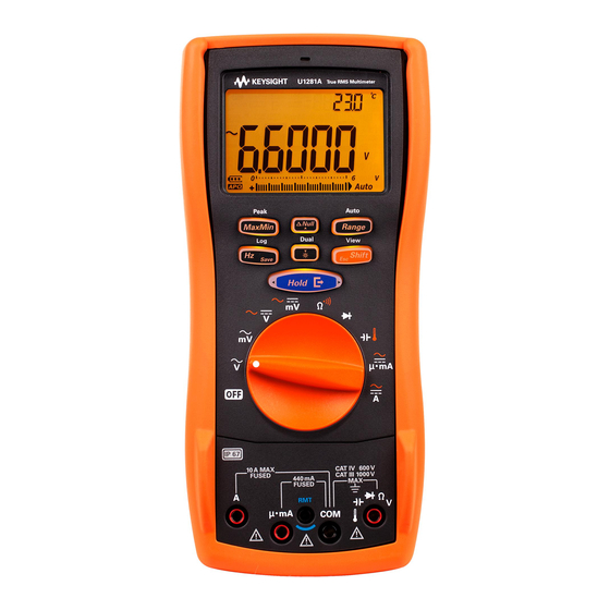
- Page 1 Keysight U1281A/U1282A Handheld Digital Multimeter User’s Guide...
- Page 2 DOCUMENT IS PROVIDED “AS IS,” sition Regulation (“FAR”) 2.101. Pursu- AND IS SUBJECT TO BEING © Keysight Technologies 2015 - 2022 ant to FAR 12.212 and 27.405-3 and CHANGED, WITHOUT NOTICE, IN No part of this manual may be repro- Department of Defense FAR Supple- FUTURE EDITIONS.
-
Page 3: Safety Symbols
(refer to this manual for specific Warning or Caution information) Equipment protected throughout by CAT IV Category IV 600 V overvoltage double insulation or reinforced protection 600 V insulation CAT III Category III 1000 V overvoltage protection 1000 V Keysight U1281A/U1282A User’s Guide... -
Page 4: Safety Considerations
Failure to comply with these precautions or with specific warnings elsewhere in this manual violates safety standards for design, manufacture, and intended use of the instrument. Keysight Technologies assumes no liability for the customer’s failure to comply with these requirements. - Page 5 – Always use the specified battery type. The power for the multimeter is supplied with four standard 1.5 V AA batteries. Observe the correct polarity markings before you insert the batteries to ensure proper insertion of the batteries in the multimeter. Keysight U1281A/U1282A User’s Guide...
-
Page 6: Measurement Category
Measurement Category The U1281A/U1282A has a safety rating of CAT III, 1000 V and CAT IV, 600 V. Measurement CAT I Measurements performed on circuits not directly connected to the AC mains. Examples are measurements on circuits not derived from the AC mains and specially protected (internal) mains-derived circuits. -
Page 7: Environmental Conditions
Environmental Conditions The U1281A/U1282A is designed for indoor use and in an area with low condensation. The table below shows the general environmental requirements for this instrument. Environmental cond ition Requirement Operating condition – –20 °C to 55 °C, 0% to 80% RH (non-condensing) -
Page 8: Regulatory Information
Regulatory Information The U1281A/U1282A complies with the following Electromagnetic Compatibility (EMC) and safety compliances: Safety compliance – IEC 61010-1/EN61010-1, IEC 61010-2-030/EN61010-2-030, IEC61010-02-033/ EN61010-2-033 – Canada: CAN/CSA C22.2 No. 61010-1, CAN/CSA-C22.2 No.61010-2-030, CAN/ CSA-C22.2 No.61010-2-033 – USA: UL Std. No.61010-1, UL Std. No.61010-2-030, UL Std. No.61010-2-033 EMC compliance –... -
Page 9: Regulatory Markings
Declaration. This is a Class A instrument elements are expected to leak or deteriorate suitable for professional use and in during normal use. Forty years is the expected electromagnetic environment outside of the useful life of the product. home. Keysight U1281A/U1282A User’s Guide... -
Page 10: Waste Electrical And Electronic Equipment (Weee) Directive 2002/96/Ec
To contact Keysight for sales and technical support, refer to the support links on the following Keysight websites: – www.keysight.com/find/U1281A www.keysight.com/find/U1282A (product-specific information and support, software and documentation updates) – www.keysight.com/find/assist (worldwide contact information for repair and service) Keysight U1281A/U1282A User’s Guide... -
Page 11: Table Of Contents
............52 Keysight U1281A/U1282A User’s Guide... - Page 12 ..........117 Keysight U1281A/U1282A User’s Guide...
- Page 13 ......140 Characteristics and Specifications Appendix A: Shift Functions Using the Shift Key Appendix B: Dual Display Combinations Using the Dual Key Keysight U1281A/U1282A User’s Guide...
- Page 14 THIS PAGE HAS BEEN INTENTIONALLY LEFT BLANK. Keysight U1281A/U1282A User’s Guide...
- Page 15 ........146 Keysight U1281A/U1282A User’s Guide...
- Page 16 THIS PAGE HAS BEEN INTENTIONALLY LEFT BLANK. Keysight U1281A/U1282A User’s Guide...
- Page 17 ......... . .83 Keysight U1281A/U1282A User’s Guide...
- Page 18 ......... . . 140 Keysight U1281A/U1282A User’s Guide...
-
Page 19: Introduction
Keysight U1281A/U1282A Handheld Digital Multimeter User’s Guide Introduction About This Manual Documentation map Preparing Your Multimeter Check the shipment Removing the holster Installing the holster Installing the batteries Turn on your multimeter Automatic power-off Enabling the backlight Selecting the range... -
Page 20: About This Manual
Introduction About This Manual Documentation map The following manuals and software related to the U1281A/U1282A Handheld Digital Multimeter are available for download. Please visit our website at http://www.keysight.com/find/hhTechLib for the latest version. Check the manual edition on the first page of each manual. -
Page 21: Preparing Your Multimeter
3 For any question or problems, refer to the Keysight contact numbers on the back of this manual. Removing the holster 1 Push the top of the orange rubber holster outward and backward. 2 Push the multimeter from the back until the orange rubber holster is completely detached from the multimeter. Keysight U1281A/U1282A User’s Guide... -
Page 22: Figure 1-1 Removing The Orange Rubber Holster
Introduction Figure 1-1 Removing the orange rubber holster Keysight U1281A/U1282A User’s Guide... -
Page 23: Installing The Holster
Use the following procedure to install the batteries. Before you proceed with the battery installation, remove all cable connections to the CAUTION terminals and ensure that the rotary switch is at the OFF position. Use only the battery type specified in the datasheet. Keysight U1281A/U1282A User’s Guide... - Page 24 8 Finally fit the orange rubber holster back on the multimeter. The battery level indicator at the lower left-hand corner of the display indicates the relative condition of the batteries. To ensure that the multimeter’s battery level indicator is Keysight U1281A/U1282A User’s Guide...
-
Page 25: Table 1-1 Battery Level Indicator
To avoid damage from battery leakage: CAUTION – Always remove dead batteries immediately. – Always remove the batteries and store them separately if the multimeter is not going to be used for a long period. Keysight U1281A/U1282A User’s Guide... -
Page 26: Turn On Your Multimeter
, then turning it to a desired measurement function. – Turning the rotary knob to another measurement function. Enabling the backlight If viewing the display becomes difficult in low-light conditions, press to activate the backlight for the LCD and the keypad. Keysight U1281A/U1282A User’s Guide... - Page 27 Introduction To conserve battery life, a user-adjustable timeout controls how long the backlight stays on. The default timeout is 15 seconds (refer to “Changing the Auto Power-Off and backlight timeouts” on page for more information). Keysight U1281A/U1282A User’s Guide...
-
Page 28: Selecting The Range
Range Each additional press of sets the multimeter to the next higher range, unless it is Range already in the highest range, at which point the range switches to the lowest range. Keysight U1281A/U1282A User’s Guide... -
Page 29: Alerts And Warnings During Measurement
Hazardous current indication table Measurement ≥ +11 A or +OL ≤ –11 A or –OL ≥ 11 A or OL μA/mA ≥ 440 mA or +OL ≤ –440 mA or –OL ≥ 440 mA or OL Keysight U1281A/U1282A User’s Guide... -
Page 30: Figure 1-4 Example Of Wrong Terminal Input
If the test leads are not removed, the sound will stop after 5 seconds. Vsense U1282A True RMS Multimeter Vsense Peak Auto Dual 10A MAX CAT IV 600V FUSED CAT III 1000V 440mA FUSED Figure 1-4 Example of wrong terminal input Keysight U1281A/U1282A User’s Guide... -
Page 31: Adjusting The Tilt Stand
Figure 1-5 Input warning display Adjusting the tilt stand To adjust the multimeter to a 60° standing position, pull the tilt-stand outward to its maximum reach. To PC (host) Figure 1-6 Tilt-stand adjustment and IR-USB cable connection Keysight U1281A/U1282A User’s Guide... -
Page 32: Remote Communication
– Keysight Handheld Meter Logger (for Windows PC) – Keysight Mobile Meter (for Android or iOS devices) – Keysight Mobile Logger (for Android or iOS devices) Snap the optic side of the U1117A to the multimeter’s IR communication port (see Figure 1-7). Keysight U1281A/U1282A User’s Guide... -
Page 33: Figure 1-7 Bluetooth Adapter Connection
Logger Software Help File for more information on the IR communication link and the Keysight Handheld Meter Logger Software. Figure 1-8 Keysight Handheld Meter Logger Software The Keysight Handheld Meter Logger Software and its supporting documents are available for download from http://www.keysight.com/find/hhmeterlogger. Keysight U1281A/U1282A User’s Guide... -
Page 34: Power-On Options
Enters the Setup mode. For more information, refer to Chapter 4, "Using the Setup Menu". Shift Triggers the exporting of data via the multimeter’s optical communication port. The reading on the primary display is exported, according to the display update rate. Restart the multimeter to resume MaxMin normal operation. Keysight U1281A/U1282A User’s Guide... -
Page 35: Your Multimeter In Brief
CAT IV 600V FUSED CAT III 1000V 440mA FUSED Figure 1-9 Front panel Table 1-5 Front panel parts Legend Description Learn more on: Vsense detector page Display screen page Keypad page Rotary switch page Terminals page Keysight U1281A/U1282A User’s Guide... -
Page 36: Table 1-6 Rear Panel Parts
“Learn more” pages for more information on each part. Figure 1-10 Rear panel Table 1-6 Rear panel parts Legend Description Learn more on: IR communication port Test probe holders Battery and fuse access cover page Tilt stand page Keysight U1281A/U1282A User’s Guide... -
Page 37: Rotary Switch
Each position of the rotary switch (shown in Figure 1-11) is described in Table 1-7. Table 1-7 Rotary switch functions Legend Description Learn more on: page AC voltage measurement with Low-Pass Filter page AC voltage measurement (up to millivolts) with Low-Pass Filter Keysight U1281A/U1282A User’s Guide... -
Page 38: Keypad
Turning the rotary switch to another position resets the current operation of the key. Click the respective “Learn more” pages for more information on each function. Vsense Peak Auto Dual Figure 1-12 Keypad keys Keysight U1281A/U1282A User’s Guide... -
Page 39: Table 1-8 Keypad Functions
(if supported by the measurement). Exits the dual d isplay mode. Turns the backlight on or off. page – Press for more than 1 second to toggle between the available dual display modes for supported measurement functions. Keysight U1281A/U1282A User’s Guide... - Page 40 1 second will enter the event data logging mode, where data is logged each time a triggering condition is satisfied. – Press for more than 1 Save second to exit the interval or event data logging mode. Keysight U1281A/U1282A User’s Guide...
- Page 41 Vsense – Press for more than 1 second to sanitize all log memories when all the logging modes have been cleared of all entries. – Press for more than 1 Shift second to exit this mode. Keysight U1281A/U1282A User’s Guide...
-
Page 42: Display Screen
Secondary measurement display AC, DC, and AC+DC indication for secondary display page and page Measuring units for the secondary display page Low-pass filter enabled for AC measurement page and page Filter enabled for DC measurement Keysight U1281A/U1282A User’s Guide... - Page 43 – Capacitor is charging (during capacitance measurement) – Positive slope for pulse width (ms) and duty cycle (%) measurements page and page – Capacitor is discharging (during capacitance measurement) – Negative slope for pulse width (ms) and duty cycle (%) measurements Keysight U1281A/U1282A User’s Guide...
- Page 44 Measurement range selected page Battery capacity indication page APO (Auto Power-Off) enabled page Tone enabled Analog bar graph page Autoranging enabled page Diode test selected page Smooth mode enabled page Overload (the reading exceeds the display range) Keysight U1281A/U1282A User’s Guide...
-
Page 45: Table 1-10 Measurement Units Display
Percent, unit for the scale proportional to DC 0~20 mA Percent, unit for the scale proportional to DC 4~20 mA °C Degree Celsius, unit for temperature measurement °F Degree Fahrenheit, unit for temperature measurement Seconds, unit for Peak and Recording mode elapsed time Keysight U1281A/U1282A User’s Guide... -
Page 46: Table 1-11 Analog Bar Graph Display
AC voltages in the circuit if the DC Filter is disabled in the Setup mode. [1] The analog bar graph measurement rate is approximately 30 times/second for DC voltage, current, and resistance measurements. Keysight U1281A/U1282A User’s Guide... -
Page 47: Input Terminals
Ensure that the terminal connections are correct for that particular measurement function WARNING before starting any measurement. To avoid damaging this multimeter, do not exceed the rated input limit. CAUTION 10A MAX CAT IV 600V FUSED CAT III 1000V 440mA FUSED Figure 1-14 Connector terminals Keysight U1281A/U1282A User’s Guide... -
Page 48: Table 1-12 Terminal Connections For Different Measuring Functions
Overload protection position 1000 Vrms 1000 Vrms for short circuit < 0.3 A 11 A/1000 V, fast-acting fuse 440 mA/1000 V, fast-acting fuse Remote probe terminal (see “Using the Remote Switch Probe” on page for more information) Keysight U1281A/U1282A User’s Guide... -
Page 49: Using The Remote Switch Probe
The location of the button on the Remote Switch Probe Connect the Remote Switch Probe to the multimeter as shown below. Figure 1-16 Remote Switch Probe connection to the multimeter To change the default button operation, see ““Changing the remote button function” on page 135. Keysight U1281A/U1282A User’s Guide... -
Page 50: Cleaning Your Multimeter
2 Turn the multimeter over and shake out any dirt that may have accumulated in the terminals. Wipe the case with a damp cloth and mild detergent — do not use abrasives or solvents. Wipe the contacts in each terminal with a clean swab dipped in alcohol. Keysight U1281A/U1282A User’s Guide... -
Page 51: Making Measurements
Keysight U1281A/U1282A Handheld Digital Multimeter User’s Guide Making Measurements Crest Factor Measuring AC Voltage Using the LPF Function for AC measurements (for U1282A only) Measuring DC Voltage Measuring AC and DC Signals Using the LPF (Low Pass Filter) Function for AC+DC measurements... -
Page 52: Crest Factor
1000 V +/– 1500 V Exceeding the crest factor limit may result in an incorrect or a lower reading. Do not WARNING exceed the crest factor limit to avoid instrument damage and the risk of electric shock. Keysight U1281A/U1282A User’s Guide... -
Page 53: Measuring Ac Voltage
NOTE – True rms (root mean square) readings. These readings are accurate for sinusoidal waves and other waveforms with no DC offset, such as square waves, triangle waves, and staircase waves. Figure 2-1 AC voltage display Keysight U1281A/U1282A User’s Guide... -
Page 54: Figure 2-2 Measuring Ac Voltage
See Save “Measuring Frequency” on page to learn more. Vsense U1282A True RMS Multimeter Vsense Peak Auto Dual 10A MAX CAT IV 600V FUSED CAT III 1000V 440mA FUSED Figure 2-2 Measuring AC voltage Keysight U1281A/U1282A User’s Guide... -
Page 55: Using The Lpf Function For Ac Measurements (For U1282A Only)
LPF. Your multimeter continues measuring in the chosen AC mode, but now the signal diverts through a filter that blocks voltages above 1 kHz (refer to Figure 2-3), as shown in Figure 2-4. 1 kHz Figure 2-3 Low-pass filter Shift Figure 2-4 Low-pass filter operation Keysight U1281A/U1282A User’s Guide... -
Page 56: Figure 2-5 Ac Voltage (With Lpf) Display
Making Measurements Probe the test points and read the display. Figure 2-5 AC voltage (with LPF) display Keysight U1281A/U1282A User’s Guide... -
Page 57: Measuring Dc Voltage
0 V or < 30 V. The measurement range will automatically be set to a higher range, and the analog bar graph will be varying faster or greater than the displayed value. Keysight U1281A/U1282A User’s Guide... -
Page 58: Figure 2-7 Measuring Dc Voltage
See Save “Measuring Frequency” on page to learn more. Vsense U1282A True RMS Multimeter Peak Vsense Auto Dual 10A MAX CAT IV 600V FUSED CAT III 1000V 440mA FUSED Figure 2-7 Measuring DC voltage Keysight U1281A/U1282A User’s Guide... -
Page 59: Measuring Ac And Dc Signals
Set up your multimeter according to your desired measurement (voltage or current measurement). Press the key twice to change the measurement function to the Shift AC+DC mode ( ). Probe the test points and read the display. Figure 2-8 AC+DC voltage display Keysight U1281A/U1282A User’s Guide... -
Page 60: Figure 2-9 Ac+Dc Current Display
(Refer to “Append ix B: Dual Display Combinations Using the Dual Key” on page for more information) – Press to enable the frequency test mode for voltage measurements. See Save “Measuring Frequency” on page to learn more. Keysight U1281A/U1282A User’s Guide... -
Page 61: Using The Lpf (Low Pass Filter) Function For Ac+Dc Measurements
2 Rotate the multimeter’s rotary switch to 3 Your multimeter continues measuring in the AC+DC mode, but now the signal diverts through a filter that blocks unwanted voltages above 1 kHz. Figure 2-10 AC+DC voltage (with LPF) display Keysight U1281A/U1282A User’s Guide... -
Page 62: Making Db Measurements
– A dBV measurement uses a 1 volt reference voltage to compare the present measurement against a stored relative value. The difference between the two AC signals is displayed as a dBV value. The reference impedance setting is not part of a dBV measurement. Keysight U1281A/U1282A User’s Guide... -
Page 63: Figure 2-11 Dbm Display
Press and hold for more than 1 second to scroll through the options until you exit the dBm or dBV function. Selecting the frequency test mode ( ) also cancels the dBm or Save dBV function. Keysight U1281A/U1282A User’s Guide... -
Page 64: Measuring Resistance
Set up your multimeter to measure resistance as shown in Figure 2-14. Probe the test points and read the display. Table 2-6 Rotary switch position allowing resistance measurements Legend Defaul t function Function when Shift is pressed Resistance measurement (Ω) Continuity test ( Figure 2-13 Resistance display Keysight U1281A/U1282A User’s Guide... -
Page 65: Figure 2-14 Measuring Resistance
Making Measurements Vsense U1282A True RMS Multimeter Vsense Peak Auto Dual 10A MAX CAT IV 600V FUSED CAT III 1000V 440mA FUSED Figure 2-14 Measuring resistance Keysight U1281A/U1282A User’s Guide... -
Page 66: Measuring Conductance
Figure 2-14. Press until the conductance measurement is selected (nS unit shown). Range Probe the test points, and read the display. High-resistance readings are susceptible to electrical noise. Use averaging to smooth out most of the noisy readings. Keysight U1281A/U1282A User’s Guide... -
Page 67: Testing For Continuity
0.109 ± 0.05 MΩ 60.000 MΩ 0.001 MΩ 1.5% +3 0.109 ± 0.05 MΩ 3.0% +3 (< 100 MΩ) 600.00 MΩ 0.01 MΩ 0.109 ± 0.05 MΩ 8.0% +3 (< 600 MΩ) 600.00 nS 0.01 nS 1% +20 None Keysight U1281A/U1282A User’s Guide... - Page 68 A brief short or open causes the multimeter to emit a short beep and flash. – You can enable or disable the audible and visual alert via the multimeter’s Setup. See “Changing the continuity alert type” on page for more information on the audible alert option. Keysight U1281A/U1282A User’s Guide...
-
Page 69: Figure 2-15 Testing For Continuity
Making Measurements Vsense U1282A True RMS Multimeter ( open) Vsense Peak Auto ( closed) Dual Shift 10A MAX CAT IV 600V FUSED CAT III 1000V 440mA FUSED Figure 2-15 Testing for continuity Keysight U1281A/U1282A User’s Guide... -
Page 70: Testing Diodes
A typical junction drop is 0.3 V to 0.8 V. – Connect the red test lead to the positive terminal (anode) of the diode and the black test lead to the negative terminal (cathode). Figure 2-16 Diode display Keysight U1281A/U1282A User’s Guide... -
Page 71: Figure 2-17 Open Diode Display
– A diode is considered shorted if the multimeter displays approximately 0 V in both forward and reverse bias modes, and the multimeter beeps continuously. – A diode is considered open if the multimeter displays in both forward and reverse bias modes. Figure 2-17 Open diode display Keysight U1281A/U1282A User’s Guide... -
Page 72: Figure 2-18 Testing A Forward-Bias Diode
Making Measurements Vsense U1282A True RMS Multimeter Vsense Peak Auto Dual 10A MAX CAT IV 600V FUSED CAT III 1000V 440mA FUSED Figure 2-18 Testing a forward-bias diode Keysight U1281A/U1282A User’s Guide... -
Page 73: Figure 2-19 Testing A Reverse-Bias Diode
Making Measurements Vsense U1282A True RMS Multimeter Peak Vsense Auto Dual 10A MAX CAT IV 600V FUSED CAT III 1000V 440mA FUSED Figure 2-19 Testing a reverse-bias diode Keysight U1281A/U1282A User’s Guide... -
Page 74: Frequency Counter (For U1282A Only)
1 Position the rotary switch to 2 Press to select the frequency counter mode. Shift 3 Probe the test points and read the display. 4 If the reading is unstable, press to toggle between a Hz or a MHz reading. Range Keysight U1281A/U1282A User’s Guide... -
Page 75: Figure 2-20 Frequency Counter Mode
Making Measurements Vsense U1282A True RMS Multimeter Vsense Peak Auto Dual Shift 10A MAX CAT IV 600V FUSED CAT III 1000V 440mA FUSED Figure 2-20 Frequency counter mode Keysight U1281A/U1282A User’s Guide... -
Page 76: Measuring Capacitance
– For measuring capacitance values greater than 1000 μF, discharge the capacitor first, then select a suitable range for measurement. This will speed up the measurement time and also ensure that the correct capacitance value is obtained. Figure 2-21 Capacitance display Keysight U1281A/U1282A User’s Guide... -
Page 77: Figure 2-22 Measuring Capacitance
Making Measurements Vsense U1282A True RMS Multimeter – Peak Vsense Auto Dual 10A MAX CAT IV 600V FUSED CAT III 1000V 440mA FUSED Figure 2-22 Measuring capacitance Keysight U1281A/U1282A User’s Guide... -
Page 78: Measuring Temperature
– Shorting the terminal to the terminal will display the temperature at the multimeter’s terminals. – To change the default thermocouple type from type-K to type-J, see “Changing the thermocouple type” on page for more information. Keysight U1281A/U1282A User’s Guide... -
Page 79: Figure 2-23 Temperature Display
– Cool down the multimeter after measuring high current signals. For quick measurement, use the compensation to view the temperature variation of the thermocouple sensor. The compensation assists you in measuring relative temperature immediately without compensating for the ambient temperature. Keysight U1281A/U1282A User’s Guide... -
Page 80: Figure 2-24 Measuring Temperature
Making Measurements Vsense U1282A True RMS Multimeter Peak Vsense Auto Dual Shift 10A MAX CAT IV 600V FUSED CAT III 1000V 440mA FUSED Figure 2-24 Measuring temperature Keysight U1281A/U1282A User’s Guide... -
Page 81: Temperature Measurement Without Ambient Compensation
3 After a constant reading is obtained, press to set the reading as the relative reference temperature. 4 Touch the surface to be measured with the thermocouple probe and read the display. Figure 2-25 Temperature measurement without ambient compensation Keysight U1281A/U1282A User’s Guide... -
Page 82: Measuring Ac Or Dc Current
Scrolls between – AC A DC A – AC+DC A, or – DC A Scrolls between – AC mA (or μA) DC mA (or μA) – AC+DC mA (or μA), or – DC mA (or μA) Keysight U1281A/U1282A User’s Guide... -
Page 83: Figure 2-26 Dc Current Display
This happens because the resistance through the multimeter’s current terminals is very low, resulting in a short circuit. Figure 2-26 DC current display Keysight U1281A/U1282A User’s Guide... - Page 84 (refer to “Append ix B: Dual Display Combinations Using the Dual Key” on page for more information). – Press to enable the frequency test mode for current measurements. See Save “Measuring Frequency” on page to learn more. Keysight U1281A/U1282A User’s Guide...
-
Page 85: Figure 2-27 Measuring Ac Or Dc Current
Making Measurements Vsense U1282A True RMS Multimeter LOAD Peak Vsense Auto Dual 10A MAX CAT IV 600V FUSED CAT III 1000V 440mA FUSED Figure 2-27 Measuring AC or DC current Keysight U1281A/U1282A User’s Guide... -
Page 86: Scale Of 4-20 Ma Or 0-20 Ma
– The % scale for 4-20 mA or 0-20 mA in this multimeter is calculated using its corresponding DC mA measurement. The multimeter will automatically optimize the best resolution for the selected measurement. Figure 2-28 4-20 mA % scale display Keysight U1281A/U1282A User’s Guide... -
Page 87: Table 2-14 % Scale Measurement Range
~ 600 mA 9999.9% [a] Applies to both autoranging and manual range selection Use the % scale with a pressure transmitter, a valve positioner, or other output actuators to measure pressure, temperature, flow, pH, or other process variables. Keysight U1281A/U1282A User’s Guide... -
Page 88: Figure 2-30 Measuring Dc Current Using The 0-20 Ma % Scale
Making Measurements Vsense U1282A True RMS Multimeter Peak Vsense Auto Dual 10A MAX CAT IV 600V FUSED CAT III 1000V 440mA FUSED Pressure transmitter Figure 2-30 Measuring DC current using the 0-20 mA % scale Keysight U1281A/U1282A User’s Guide... -
Page 89: Measuring Frequency
To measure frequency, rotate the switch to one of the primary functions allowing frequency measurements highlighted in Table 2-15. Press , then probe the test points and Save read the display. Pressing controls the input range of the voltage or ampere function, not the Range frequency range. Keysight U1281A/U1282A User’s Guide... -
Page 90: Figure 2-31 Frequency Display
– To obtain the best measuring results for frequency measurements, please use the AC measuring path. Rise Time Fall Time + Width - Width Period Figure 2-32 Frequency, pulse width, and duty cycle measurements Keysight U1281A/U1282A User’s Guide... - Page 91 Press to scroll through the frequency, pulse width, and duty cycle measurements. Save Press to scroll back to the frequency measurement mode, and hold for more Save than 1 second to exit the frequency measurement function. Keysight U1281A/U1282A User’s Guide...
-
Page 92: Measuring Pulse Width
Press to scroll through the frequency, pulse width, and duty cycle measurements. Save Press to scroll back to the frequency measurement mode, and hold for more Save than 1 second to exit the frequency measurement function. Keysight U1281A/U1282A User’s Guide... -
Page 93: Measuring Duty Cycle
Press to scroll through the frequency, pulse width, and duty cycle measurements. Save Press to scroll back to the frequency measurement mode, and hold for more Save than 1 second to exit the frequency measurement function. Keysight U1281A/U1282A User’s Guide... -
Page 94: Square Wave Output
Shift 3 Press to scroll through the available frequencies Hold Save (there are 29 frequencies to choose from). Vsense 4 Press to change the duty cycle or pulse width values. Figure 2-35 Square wave output display Keysight U1281A/U1282A User’s Guide... -
Page 95: Figure 2-36 Square Wave Output
Making Measurements Vsense U1282A True RMS Multimeter Vsense Peak Auto Dual oscilloscope 10A MAX CAT IV 600V FUSED CAT III 1000V 440mA FUSED Figure 2-36 Square wave output Keysight U1281A/U1282A User’s Guide... - Page 96 Making Measurements THIS PAGE HAS BEEN INTENTIONALLY LEFT BLANK. Keysight U1281A/U1282A User’s Guide...
-
Page 97: Multimeter Features
Keysight U1281A/U1282A Handheld Digital Multimeter User’s Guide Multimeter Features Non-Contact AC Voltage Detection (Vsense) Making Relative Measurements (Null) Capturing Maximum and Minimum Values (MaxMin) Capturing Peak Values (Peak) Freezing the Display (TrigHold and AutoHold) Recording Measurement Data (Data Logging) Performing manual logs (HAnd) -
Page 98: Non-Contact Ac Voltage Detection (Vsense)
3 Press and hold again to disable Vsense. When Vsense is disabled, the multimeter will return to the primary function of the current NOTE rotary knob position regardless of what function it was in before Vsense was enabled. Keysight U1281A/U1282A User’s Guide... -
Page 99: Figure 3-1 Non-Contact Ac Voltage Detector (Vsense) Mode
AC voltage source Vsense Vsense beeper sounds U1282A True RMS Multimeter > 1 sec. Vsense Peak Auto Vsense Dual 10A MAX CAT IV 600V FUSED CAT III 1000V 440mA FUSED Figure 3-1 Non-contact AC voltage detector (Vsense) mode Keysight U1281A/U1282A User’s Guide... -
Page 100: Making Relative Measurements (Null)
For any measurement function, you can directly measure and store the null value by Vsense pressing with the test leads open (nulls the test lead capacitance), shorted (nulls the test lead resistance), or across a desired null value circuit. Keysight U1281A/U1282A User’s Guide... -
Page 101: Figure 3-3 Null Operation
Vsense Press to enable the Null function. The display Vsense returns to Press normal after 3 seconds Flashing Vsense Press again to disable the Null function. Figure 3-3 Null operation Keysight U1281A/U1282A User’s Guide... -
Page 102: Capturing Maximum And Minimum Values (Maxmin)
2 Press again to scroll through the Max, Min, Avg, or present (MaxMinAvg) input MaxMin values. Figure 3-4 MaxMin display 3 The elapsed time is shown on the secondary display. Press to restart the Hold recording session. Keysight U1281A/U1282A User’s Guide... - Page 103 The average value displayed is the true arithmetic mean of all readings taken since the start of recording. The average reading is useful for smoothing out unstable inputs, calculating power consumption, or estimating the percentage of time a circuit is active. Keysight U1281A/U1282A User’s Guide...
-
Page 104: Capturing Peak Values (Peak)
At the same time, the elapsed time since the peak recording session was started is stored as the recorded value’s time stamp. The Auto Power-Off (APO) function is disabled when Peak is enabled. NOTE Keysight U1281A/U1282A User’s Guide... -
Page 105: Figure 3-6 Peak Hold Operation
1 second to start the Peak Hold recording session. Start to capture Press Hold to reset the recording Press to switch MaxMin session. between the maximum and minimum peak values. Figure 3-6 Peak hold operation Keysight U1281A/U1282A User’s Guide... -
Page 106: Freezing The Display (Trighold And Autohold)
3 to edit. 5 Press to save the changes. Press and hold until the multimeter restarts. Shift Save If the reading value is unable to reach a stable state, the reading value will not be updated. NOTE Keysight U1281A/U1282A User’s Guide... -
Page 107: Recording Measurement Data (Data Logging)
Vsense 3 Press to change the data logging option. Available options: , or 4 Press to save the changes. Press and hold until the multimeter restarts. Shift Save Keysight U1281A/U1282A User’s Guide... -
Page 108: Performing Manual Logs (Hand)
Shift Save The duration set in the steps above will determine how long each recording interval takes. The input signal value at the end of each interval will be recorded and saved into the multimeter’s memory. Keysight U1281A/U1282A User’s Guide... -
Page 109: Figure 3-8 Interval Log Display
When the interval log recording session is running, all other keypad operations are NOTE disabled; except for , which, when pressed for more than 1 second, will stop and exit Save the recording session. Furthermore, APO (Auto Power-Off) is disabled during the recording session. Keysight U1281A/U1282A User’s Guide... -
Page 110: Performing Event Logs (Trig)
Table 3-2 is satisfied. The display will return to normal after a short while (around 1 second). Figure 3-9 Event log display Keysight U1281A/U1282A User’s Guide... -
Page 111: Performing Export Logs
In AutoHold mode, are displayed at the top of the display, along with . The will disappear after a short while (around 1 second), but will remain. Figure 3-10 Export log display (TrigHold mode) Keysight U1281A/U1282A User’s Guide... -
Page 112: Figure 3-11 Export Log Display (Autohold Mode)
When all entries are occupied, will be shown in the secondary display when Save is pressed for more than 1 second. See the Reviewing Previously Recorded Data (View) section later in this manual to review or erase the recorded entries. Keysight U1281A/U1282A User’s Guide... -
Page 113: Reviewing Previously Recorded Data (View)
1 second to clear all Save entries for the selected log type. 4 Press for more than 1 second to exit the View mode. Shift Keysight U1281A/U1282A User’s Guide... -
Page 114: Sanitizing The Log Memories
1 second to sanitize the log entries. The data sanitization operation may take up to 1-2 minutes to complete. Do not press any CAUTION keys or turn the rotary switch until the data sanitization operation is completed. Keysight U1281A/U1282A User’s Guide... -
Page 115: Multimeter Setup Options
Keysight U1281A/U1282A Handheld Digital Multimeter User’s Guide Multimeter Setup Options Using the Setup Menu Editing numerical values Setup Menu Summary Setup Menu Items Changing the variation count Enabling smooth mode Changing the Auto Power-Off and backlight timeouts Changing the recording option... -
Page 116: Using The Setup Menu
While the menu item is flashing, press to save your changes. Save Save The multimeter will automatically exit the Setup menu after 30 seconds of inactivity. NOTE Keysight U1281A/U1282A User’s Guide... -
Page 117: Editing Numerical Values
When you have completed your changes, save the new numerical value by pressing . (Alternatively, if you wish to discard the changes you made, press Shift Save Press and hold to exit the Setup menu. Shift Keysight U1281A/U1282A User’s Guide... -
Page 118: Setup Menu Summary
1 Ω to 0001 to 9999 Ω page and page 9999 Ω. Default is 50 Ω. Set the multimeter’s thermocouple type (type J or tYPE J or tYPE K page and page type K). Default is type K. Keysight U1281A/U1282A User’s Guide... - Page 119 Set the display count to high (ddddd) or low (dddd) ddddd or dddd page resolution. Default is (ddddd) Set the multimeter’s display refresh rate to either 5 or 40 5 or 40 page times/second. Default is 5 times/second Keysight U1281A/U1282A User’s Guide...
- Page 120 Enables and disables the for AC voltage or current oFF or on page measurement. Default is (oFF). NOTE Press and hold the button for more than 1 second to select the temperature unit MaxMin menu for settling. Keysight U1281A/U1282A User’s Guide...
-
Page 121: Setup Menu Items
Hold step 3 to edit. 5 Press to save your changes, or press to discard your changes. Shift Save 6 Press and hold until the multimeter restarts to return to normal operation. Shift Keysight U1281A/U1282A User’s Guide... -
Page 122: Enabling Smooth Mode
Hold step 3 to edit. 5 Press to save your changes, or press to discard your changes. Shift Save 6 Press and hold until the multimeter restarts to return to normal operation. Shift Keysight U1281A/U1282A User’s Guide... -
Page 123: Changing The Auto Power-Off And Backlight Timeouts
Hold step 3 to edit. 5 Press to save your changes, or press to discard your changes. Shift Save 6 Press and hold until the multimeter restarts to return to normal operation. Shift Keysight U1281A/U1282A User’s Guide... -
Page 124: Changing The Recording Option
Vsense 3 Press to set the recording option. 4 Press to save your changes, or press to discard your changes. Shift Save 5 Press and hold until the multimeter restarts to return to normal operation. Shift Keysight U1281A/U1282A User’s Guide... -
Page 125: Changing The Sample Interval Duration
Hold step 3 to edit. 5 Press to save your changes, or press to discard your changes. Shift Save 6 Press and hold until the multimeter restarts to return to normal operation. Shift Keysight U1281A/U1282A User’s Guide... -
Page 126: Setting A Custom Dbm Reference Impedance
Hold step 3 to edit. 5 Press to save your changes, or press to discard your changes. Shift Save 6 Press and hold until the multimeter restarts to return to normal operation. Shift Keysight U1281A/U1282A User’s Guide... -
Page 127: Changing The Thermocouple Type
Shift Save 5 Press and hold until the multimeter restarts to return to normal operation. Shift This Setup menu item is only applicable for the U1282A. NOTE Keysight U1281A/U1282A User’s Guide... -
Page 128: Changing The Temperature Unit
Vsense 3 Press to change the temperature unit. 4 Press to save your changes, or press to discard your changes. Shift Save 5 Press and hold until the multimeter restarts to return to normal operation. Shift Keysight U1281A/U1282A User’s Guide... -
Page 129: Changing The Beep Frequency
Hold step 3 to edit. 5 Press to save your changes, or press to discard your changes. Shift Save 6 Press and hold until the multimeter restarts to return to normal operation. Shift Keysight U1281A/U1282A User’s Guide... -
Page 130: Changing The Startup Sound
Select to disable the startup sound. 4 Press to save your changes, or press to discard your changes. Shift Save 5 Press and hold until the multimeter restarts to return to normal operation. Shift Keysight U1281A/U1282A User’s Guide... -
Page 131: Changing The Continuity Type
Vsense 3 Press to set the continuity type. 4 Press to save your changes, or press to discard your changes. Shift Save 5 Press and hold until the multimeter restarts to return to normal operation. Shift Keysight U1281A/U1282A User’s Guide... -
Page 132: Changing The Continuity Alert Type
Hold step 3 to edit. 5 Press to save your changes or press to discard your changes. Shift Save 6 Press and hold until the multimeter restarts to return to normal operation. Shift Keysight U1281A/U1282A User’s Guide... -
Page 133: Changing The Battery Type
Vsense 3 Press to change the battery type. 4 Press to save your changes, or press to discard your changes. Shift Save 5 Press and hold until the multimeter restarts to return to normal operation. Shift Keysight U1281A/U1282A User’s Guide... -
Page 134: Resetting The Multimeter's Setup Options
Shift Save 5 The multimeter will beep once and return to the first Setup menu item ( All the settings will be reset to their default values except the temperature units. NOTE Keysight U1281A/U1282A User’s Guide... -
Page 135: Changing The Remote Button Function
Hold step 3 to edit. 5 Press to save your changes, or press to discard your changes. Shift Save 6 Press and hold until the multimeter restarts to return to normal operation. Shift Keysight U1281A/U1282A User’s Guide... -
Page 136: Setting The Display Count
Vsense 3 Press to set the display count. 4 Press to save your changes, or press to discard your changes. Shift Save 5 Press and hold until the multimeter restarts to return to normal operation. Shift Keysight U1281A/U1282A User’s Guide... -
Page 137: Setting The Data Refresh Rate
3 Press to set the data refresh rate. 4 Press to save your changes, or press to discard your changes. Shift Save 5 Press and hold until the multimeter restarts to return to normal operation. Shift Keysight U1281A/U1282A User’s Guide... -
Page 138: Setting The Input Impedance
Vsense 3 Press to set the input impedance. 4 Press to save your changes, or press to discard your changes. Shift Save 5 Press and hold until the multimeter restarts to return to normal operation. Shift Keysight U1281A/U1282A User’s Guide... -
Page 139: Enabling The Dc Path Filter
3 Press to enable or disable the filter. 4 Press to save your changes, or press to discard your changes. Shift Save 5 Press and hold until the multimeter restarts to return to normal operation. Shift Keysight U1281A/U1282A User’s Guide... -
Page 140: Enabling The Ac Path Filter (For U1282A Only)
3 Press to enable or disable the filter. 4 Press to save your changes, or press to discard your changes. Shift Save 5 Press and hold until the multimeter restarts to return to normal operation. Shift Keysight U1281A/U1282A User’s Guide... -
Page 141: Characteristics And Specifications
Keysight U1281A/U1282A Handheld Digital Multimeter User’s Guide Characteristics and Specifications For the characteristics and specifications of the U1281A/U1282A Handheld Digital Multimeter, refer to the datasheet at http://literature.cdn.keysight.com/litweb/pdf/5992-0847EN.pdf. - Page 142 Characteristics and Specifications THIS PAGE HAS BEEN INTENTIONALLY LEFT BLANK. Keysight U1281A/U1282A User’s Guide...
-
Page 143: Appendix A: Shift Functions Using The Shift Key
Keysight U1281A/U1282A True RMS Multimeter User’s Guide Appendix A: Shift Functions Using the Shift Key Default and shift functions The table below lists the functions shown in the primary display when the key is Shift pressed, with respect to the multimeter’s rotary switch position. Press... -
Page 144: Table A-1 Default And Shift Functions
AC current measurement (AC A) DC current measurement (DC A) With the positive probe AC+DC current measurement (AC+DC A) inserted into the terminal Square wave output (duty cycle mode) Square wave output (pulse width mode) Keysight U1281A/U1282A User’s Guide... -
Page 145: Appendix B: Dual Display Combinations Using The Dual Key
Keysight U1281A/U1282A True RMS Multimeter User’s Guide Appendix B: Dual Display Combinations Using the Dual Dual display combinations The table below lists the functions shown in the secondary display when the key is pressed and held for more than 1 second, with respect to the multimeter’s rotary switch position. - Page 146 AC+DC voltage Ambient dBV measurement AC+DC voltage measurement temperature (dBV V) measurement (AC+DC V) (AC+DC V) AC+DC voltage AC voltage measurement (AC+DC V) measurement (AC V) AC+DC voltage DC voltage measurement (AC+DC V) measurement (DC V) Keysight U1281A/U1282A User’s Guide...
-
Page 147: Table B-1 Dual Display Combinations
AC voltage measurement measurement (AC mV) (AC+DC mV) AC+DC voltage DC voltage measurement measurement (DC mV) (AC+DC mV) Resistance measurement (Ω) Continuity test ( Diode test (V) Frequency counter (Hz/MHz) Capacitance measurement (F) Temperature measurement (°C/°F) Keysight U1281A/U1282A User’s Guide... - Page 148 (AC+DC A) (AC+DC A) AC+DC current DC current measurement measurement (DC A) (AC+DC A) Square wave output Square wave output (duty cycle mode) frequency value Square wave output Square wave output (pulse width mode) frequency value Keysight U1281A/U1282A User’s Guide...
- Page 149 This information is subject to change without notice. Always refer to the English version at the Keysight Web site for the latest revision. © Keysight Technologies 2015 - 2022 Edition 02, February 2022 Printed in Malaysia U1281-90003 www.keysight.com...
Need help?
Do you have a question about the U1281A and is the answer not in the manual?
Questions and answers