
Subscribe to Our Youtube Channel
Related Manuals for Keysight Technologies U5309A


Summary of Contents for Keysight Technologies U5309A
- Page 1 Startup Guide Keysight U5309A PCIe High-Speed Digitizer 2 or 8 channels, 8-bit, up to 2 GS/s, DC to 500 GHz bandwidth, with custom firmware support...
- Page 2 Copyright Notice HEREIN. SHOULD KEYSIGHT AND THE public to use, modify, reproduce, © Keysight Technologies 2013 - 2016 USER HAVE A SEPARATE WRITTEN release, perform, display, or disclose No part of this manual may be...
- Page 3 temperature range is not maintained, safety precautions required to avoid intended to be used with impedance- module surface temperatures may possible injury. Read and follow all limited sources. NEVER connect exceed safe handling conditions which installation, operation, and switching cards directly to AC mains. can cause discomfort or burns if maintenance information carefully When connecting sources to switching...
- Page 4 For continued To prevent electrical shock, disconnect To return unwanted products, contact protection against fire hazard, replace the Keysight Technologies instrument your local Keysight office, or for more fuse with same type and rating. from mains before cleaning. Use a dry...
-
Page 5: Table Of Contents
Fitting the module with the optional card retainer into your PC U5309A Front Panel Features Front Panel Connectors Front Panel LEDs Step 5: Verify Operation of the U5309A Module Keysight Connection Expert Driver Graphical Interface: MD2 Soft Front Panel Perform a Verification of the U5309A (optional) -
Page 6: Documentation Map
Documentation Map Documentation Map Keysight U5309A Startup Guide... -
Page 7: U5309A Pcie High-Speed Digitizer Introduction
U5309A PCIe High-Speed Digitizer Introduction The scope of this Startup Guide is to detail the processes of receiving and installing the Keysight U5309A PCIe High-Speed Digitizer, installing the required software, and verifying basic module operation. If you have any questions after reviewing this information, please contact your local Keysight representative or contact us through our website at www.keysight.com/find/contactus. - Page 8 This Start-Up Guide is intended to lead the user through the four steps of product installation as summarized in the diagram below. An optional fifth step shows how to perform an operational verification of the U5309A PCIe High-Speed Digitizer. Step 1: Unpack and Inspect...
-
Page 9: Step 1: Unpack And Inspect The Module
(see warranty information at beginning of this document). To avoid damage when handling a module, do not touch any exposed components or connector pins. http://www.keysight.com/find/tips for information on preventing damage to your Keysight equipment. Keysight U5309A Startup Guide... -
Page 10: Return A Module For Service
Name and address of owner. A P.O. box is not acceptable as a return address. Product model number (for example, U5309A). Product serial number. The serial number label is located on the top cover of the module. The serial number can also be read from the Soft Front Panel interface, but only after the hardware is installed. -
Page 11: Step 2: Verify U5309A Shipment Contents
Step 2: Verify U5309A Shipment Contents Step 2: Verify U5309A Shipment Contents The following items are also included with your U5309A PCIe High-Speed Digitizer order: Part Number Quantity Description U5309A PCIe High-Speed Digitizer. U1092-80001 Coaxial cable, MMCX (male) to BNC (male), 1 m. -
Page 12: Step 3: Install The Software
Keysight IO Libraries Suite (IOLS) The Keysight IO Libraries Suite (IOLS) contains the Keysight Connection Expert. This software is included with your shipment (CD part number E2094-60003), and is also available at www.keysight.com/find/IOsuite. This software must be installed first. Keysight U5309A Startup Guide... -
Page 13: Instrument Software
2. From the High-Speed Digitizers Applications DVD launch the installer. 3. Follow the installer prompts and select the applications your want to install. For complete list of application options supported by your digitizer, please refer to product’s datasheet. Keysight U5309A Startup Guide... -
Page 14: Step 4: Install The Module
Follow ESD precautions when handling and installing the U5309A. 2. The U5309A features a x8 PCIe bus interface, and should be installed in either a x8 or x16 PCIe slot. 3. When installing the U5309A, ensure that it has optimum cooling. Do not install it in a position where the integrated cooling fans may be obstructed. -
Page 15: Fitting The Module With The Optional Card Retainer Into Your Pc
When disconnecting the auxiliary power cable, it is important to push it away from the PCB side of the U5309A in order to disengage the friction lock. Failure to do this could cause the module side of the connector to be withdrawn at the same time thus damaging it. - Page 16 4. Slide the fan unit back towards the module until it is fully seated into the sup- port slots. 5. Refit the four screws, push the fan unit upwards away from the circuit board and tighten the four screws (0.5 Nm torque). Keysight U5309A Startup Guide...
-
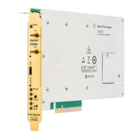
Page 17: U5309A Front Panel Features
(U1092A-CB3) A 1 m SSMC to BNC cable is also available (U5300A-100). For the 2 channels version (U5309A-CH2 option) For the 8 channels version (U5309A-CH8 option) For modules delivered after April 2015. The driver automatically adjusts offset accordingly. -
Page 18: Front Panel Leds
If warning or error status is observed, please try the following steps: Power-cycle the PC (If using a PCIe expansion chassis, observe the power sequence requirements) If the error persists please contact Keysight technical support http://www.key- sight.com/find/assist. Keysight U5309A Startup Guide... -
Page 19: Step 5: Verify Operation Of The U5309A Module
Step 5: Verify Operation of the U5309A Module Step 5: Verify Operation of the U5309A Module Keysight Connection Expert The intention of this step is to verify correct operation of the newly installed module. Run Keysight Connection Expert by clicking the task bar icon , and select Connection Expert. -
Page 20: Driver Graphical Interface: Md2 Soft Front Panel
Step 5: Verify Operation of the U5309A Module Driver Graphical Interface: MD2 Soft Front Panel The Keysight MD2 SFP (Soft Front Pannel) is a graphical interface for High-Speed Digitizer Instrument Drivers that enables the control of any supported digitizers. The MD2 SFP can be launched from Keysight Connection Expert, directly from the Windows Start Menu >... -
Page 21: Perform A Verification Of The U5309A (Optional)
Perform a Verification of the U5309A (optional) Requirements for Verification The correct operation of the U5309A may be verified by the use of a simple application which carries out several performance checks on a signal acquired from an external Function Generator. - Page 22 Step 5: Verify Operation of the U5309A Module AgMD2Verify checks the version of the Control FPGA firmware. If the version is not up-to-date, the tool will automatically propose to update the firmware using the "Firmware Update Utility". Once the Control FPGA firmware has been updated successfully, please power off your computer and restart it again for the update to take effect.
- Page 23 Keysight U5309A Startup Guide...
- Page 24 This information is subject to change without notice. © Keysight Technologies 2013 - 2016 Edition 6, January, 2016 Printed In USA U5309-90001 www.keysight.com...
Need help?
Do you have a question about the U5309A and is the answer not in the manual?
Questions and answers