Table of Contents
Advertisement
Quick Links
Advertisement
Table of Contents
Troubleshooting

Related Manuals for Bayer HealthCare CLINITEK 500


Summary of Contents for Bayer HealthCare CLINITEK 500
- Page 1 Urine Chemistry Analyzer...
- Page 2 ©1998, 2003 Bayer HealthCare LLC All Rights Reserved Printed in Ireland SECOND EDITION Unless otherwise noted, all trademarks are the property of Bayer HealthCare LLC. Manufactured in the UK for Bayer Bayer HealthCare LLC Subsidiary of Bayer Corporation Tarrytown, NY 10591-5097 USA Bayer Diagnostics Europe Limited Chapel Lane, Swords, Co.
-
Page 3: Table Of Contents
TABLE OF CONTENTS Section Page INTRODUCTION General Description and Intended Use ............1.1 Components and Mechanical Operation . - Page 4 TABLE OF CONTENTS Section Page INSTRUMENT OPERATION Continued End-of-Run Reports............... . 4.8 Editing Results in the Confirmatory Report.
-
Page 5: Introduction
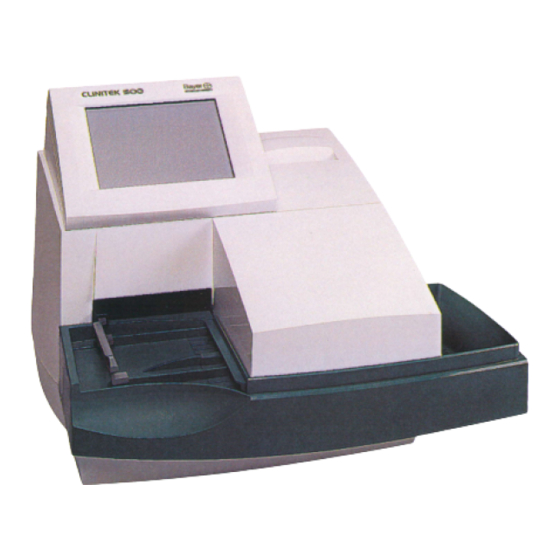
Operation a program card that contains the programming necessary for the CLINITEK 500 instrument to read these Reagent Figures 1-2 and 1-3 show the major components of the Strips. Strips can be laid on the instrument at any time (if CLINITEK ®... - Page 6 INTRODUCTION The fixed platform ‹%£ consists of three sections: the Figure 1-4 shows the rear view of the CLINITEK 500 instrument. The line cord is connected into the line cord strip loading station , the incubation/read station receptacle ‹*£. The instrument is turned on by pressing and the waste bin .
-
Page 7: Optical System
(including those selected by the user) are also stored on the program card and can be copied to Calibration other CLINITEK 500 instruments. Calibration is performed at each readhead immediately before each Reagent Strip is read. The fixed platform contains two white calibration bars that are positioned directly under each readhead. -
Page 8: Specifications
INTRODUCTION Specifications ment meets the provisions of the IVD Directive 98/79/EC (Oct./1998) ( ), which includes the EMC Directive 89/336 Amendment 92/31/EEC and the Low Voltage Power Required: Safety Directive 73/23/EEC. 100–240 VAC 10%, 50–60 Hz The safety standards specify that the instrument must Maximum Power Input: operate safely in the following conditions: 72 VA... -
Page 9: Tables Of Results
TABLES OF RESULTS Traditional Bayer Reagent Strips Reported Results Test Abbreviation Units Normal System Plus System NEGATIVE NEGATIVE Glucose mg/dL >=1000 TRACE NEGATIVE MODERATE NEGATIVE Bilirubin SMALL LARGE NEGATIVE NEGATIVE Ketone mg/dL TRACE >=80 TRACE <=1.005 1.020 Specific Gravity 1.010 1.025 No Difference 1.015... - Page 10 INTRODUCTION Traditional Bayer Reagent Strips Reported Results Reported Results Test Test Abbreviation Abbreviation Units Units Normal System Normal System Plus System Plus System NEGATIVE NEGATIVE NEGATIVE NEGATIVE Glucose Glucose TRACE TRACE NEGATIVE NEGATIVE Bilirubin Bilirubin No Difference No Difference NEGATIVE NEGATIVE NEGATIVE NEGATIVE...
- Page 11 Traditional Bayer Reagent Strips Reported Results Test Abbreviation Units Normal System Plus System NEGATIVE NEGATIVE Glucose mmol/L >=55 TRACE NEGATIVE MODERATE NEGATIVE Bilirubin SMALL LARGE NEGATIVE NEGATIVE Ketone mmol/L TRACE >=7.8 TRACE <=1.005 1.020 Specific Gravity 1.010 1.025 No Difference 1.015 >=1.030 NEGATIVE...
- Page 12 INTRODUCTION MULTISTIX PRO Reagent Strips Printed/Displayed Results Test Abbreviation Units Normal System +/– System NEGATIVE NEGATIVE Glucose mg/dL >=1000 TRACE NEGATIVE MODERATE NEGATIVE Bilirubin SMALL LARGE NEGATIVE NEGATIVE Ketone mg/dL TRACE >=80 TRACE <=1.005 1.020 Specific Gravity 1.010 1.025 No Difference 1.015 >=1.030 NEGATIVE...
- Page 13 MULTISTIX PRO Reagent Strips Printed/Displayed Results Test Abbreviation Units Normal System +/– System NEGATIVE NEGATIVE Glucose TRACE NEGATIVE Bilirubin No Difference NEGATIVE NEGATIVE Ketone TRACE <=1.005 1.020 Specific Gravity 1.010 1.025 No Difference 1.015 >=1.030 NEGATIVE Occult Blood No Difference INTACT No Difference >=9.0...
- Page 14 INTRODUCTION MULTISTIX PRO Reagent Strips Printed/Displayed Results Test Abbreviation Units Normal System +/– System NEGATIVE NEGATIVE Glucose mmol/L >=55 TRACE NEGATIVE MODERATE NEGATIVE Bilirubin SMALL LARGE NEGATIVE NEGATIVE Ketone mmol/L TRACE >=7.8 TRACE <=1.005 1.020 Specific Gravity 1.010 1.025 No Difference 1.015 >=1.030 NEGATIVE...
-
Page 15: Installation
Do not place it on the same bench as a source of vibration, such as a centrifuge. The CLINITEK 500 instrument should not be used in an explosive atmosphere. The bench space should be large enough to allow free air circulation around the instrument (3 inches/7.6 cm on all sides). -
Page 16: Instrument Setup
Bayer representative for your warranty information if this page is not included in your manual). NOTE: Retain the CLINITEK 500 shipping carton and packing for at least several weeks. If the instrument ever needs to be shipped, the shipping carton will afford the best protection against damage. - Page 17 4. Install the moving table as follows: CAUTION: If the platform does not push in at least halfway with only very gentle pressure, do not force a. Hold the table with the small rectangular tab fac- it! Ensure that the moving table is correctly positioned ing to the back.
- Page 18 INSTALLATION 8. Install a roll of printer paper and re-install the printer cover as follows: a. Notice the large tab on the back side of the instru- ment that secures the cover in place (Figure 2-8). Press in firmly on the bottom edge of the tab and lift the cover off.
-
Page 19: Interfacing To A Printer
Interfacing to a Printer The CLINITEK 500 can be interfaced to most 80- column, continuous feed printers or to the CLINITEK ® Form Printer via the printer (parallel) port that is found on the rear of the instrument. 1. Some printers may include an interface cable that is appropriate for use;... -
Page 20: Interfacing To A Computer
The system then does several inter- The CLINITEK 500 can also be interfaced to a host nal checks and procedures. Each check and its status computer or LIS (Laboratory Information System) via the is displayed while the testing is being performed. - Page 21 8. With satisfactory completion of the initial instrument display will be shown as dimmed (partially lit) check, the CLINITEK 500 Analyzer is ready for rou- symbols. tine testing. Enter the Setup Routine and follow the displayed prompts to customize the software for your laboratory.
-
Page 23: Selecting Your Options
Section 3 SELECTING YOUR OPTIONS General Information Touching this key causes a Help screen to be dis- played that has information pertaining to the screen from which the key was touched. Touch the All interaction between the operator and the Help key from the Help screen to return to the CLINITEK... - Page 24 SELECTING YOUR OPTIONS Move Up displays the previous stored result or Allows one or more records from a displayed list entry in descending order (lower sequence num- to be printed. Move Print ber). Move Up 10 displays the record stored ten positions lower than the currently displayed Allows one or more records from a displayed list record;...
-
Page 25: Setup Routine
Setup Routine Set options. The Setup Routine should be entered when the instru- ment is initially installed to select the various param- eters desired by your laboratory. Thereafter, this routine Tech ID: will probably be entered infrequently. Several of the options can be accessed freely;... - Page 26 SELECTING YOUR OPTIONS A. Setup Menu #1 b. Enter the correct date by touching the proper numer- ic keys, or touch the arrow keys to move the The first Setup menu is displayed; for example: cursor to the digit that needs to be changed and enter the correct number.
-
Page 27: Password Screen
4. Printer: 4. a. iii. external printer option (see NOTE 2 below). The a. Touch the Printer key symbol to change several “Form Printer 3” option is appropriate for use printer options: with the Star Form Printer, available from Bayer Corporation as Product No. - Page 28 • Test: Many configurations of Bayer Reagent Strips can be used on the CLINITEK 500 Analyzer. However, Set options. not all configurations are available in every country. Be sure the Reagent Strip selected agrees with the name of the Bayer Reagent Strip being used.
-
Page 29: Setup Menu #4
1. Tests to report and their order: cycle keys. The available options are: Even if an analyte or physical parameter is tested on the CLINITEK 500 Analyzer, you may choose to not report it; you can also select the order in which the Date format: Date separator: tests are reported. - Page 30 SELECTING YOUR OPTIONS c. If you want to change the order in which tests are Select tests to report and reported, touch the cycle key at the first position their order. you want to change. Any test(s) not already listed will be displayed first;...
- Page 31 If Protein has been selected as a reported test, the b. When all limits have been set, touch to return first screen shows three different options for Protein, to the previous option menu. one for each of the different groups of Bayer Reagent NOTE: This option can be selected only if “Mark pos- Strips that can be used on the instrument.
- Page 32 (in Step E-1 previously), it can either be deter- BROWN, and OTHER). Remove or add color mined by the CLINITEK 500 Analyzer or be entered options, or change their descriptions, as needed, manually by the technician from a visual determina-...
- Page 33 G. Setup Menu #6 Color: Clarity: Touch to move to the next Setup menu when all YELLOW GREEN CLEAR TURBID selections have been made on the fifth menu. The new ORANGE BLUE SL CLOUDY OTHER menu is displayed as, for example: BROWN CLOUDY *OTHER...
- Page 34 SELECTING YOUR OPTIONS H. Setup Menu #7 I. Setup Menu #8 When all options have been selected on the sixth menu, When all options have been selected on the seventh touch to progress to the next menu in the Setup menu, touch to progress to the next Setup menu.
- Page 35 An optional Handheld Bar Code Reader is available for gram that allows the transfer of results from either use with the CLINITEK 500 Analyzer. This reader can a CLINITEK ® 200+ or a CLINITEK ®...
- Page 36 SELECTING YOUR OPTIONS can allow the reader to automatically detect the for- c.to a maximum of 18). Characters can be ignored mat type. The label options are: Auto detect; Code as leading characters (at the beginning of the bar 39; I-2 of 5 (Interleaved 2 of 5); Codabar; and Code code), trailing characters (at the end), or a combi- 128.
- Page 37 J. Setup Menu #9 b. Serial port: This test sends data from the serial port, through a connector, and back into the same When all options have been selected on the eighth port. The data sent and received should be identical. menu, touch to progress to the final menu in the Setup 2.
-
Page 38: When Setup Is Complete
Analyzer memory. Conversely, if the Ready/Run screen. you receive a new CLINITEK 500 Analyzer, but have retained your old program card, you can select to use your current setup configuration from the program card. If both... -
Page 39: Software Flow Chart
SOFTWARE FLOW CHART Ready/Run Screen SEQ # Color Clarity Menu Menu Option Memory Tech ID Controls Setup Print Touch to select: Touch to enter Touch to enter Touch to enter Touch to print: • All patient results Tech ID control Lot # and Setup Routine •... -
Page 41: Instrument Operation
If ID numbers have been entered into a loadlist, the number of the next specimen in the list is displayed. The CLINITEK 500 instrument is designed to be left The number is updated each time a strip is moved to on at all times (except during cleaning procedures). - Page 42 Bayer Corporation does not war- Controls rant use of the CLINITEK 500 Analyzer with any reagent strip other than Bayer Brand Reagent Strips. Setup 2. Inspect the strip loading station and push bar for cleanliness and correct positioning.
-
Page 43: Testing Controls
Positive and Negative Control Strips for the entire length of the Reagent Strip against the side Urinalysis are available for use on the CLINITEK 500 of the container to remove excess control solution. Analyzer. The solutions prepared using the Control Strips 4. -
Page 44: Testing Routine Specimens
Step e. strip to be incorrectly aligned under the readheads. e. CLINITEK 500 instrument malfunction. Perform an 5. Repeat Steps 2-b through 4 for each additional Initial Instrument Check procedure (see Section 2). - Page 45 2. Completely immerse all reagent areas of a Bayer 4. The presence of the Reagent Strip is detected as soon Reagent Strip in fresh, well-mixed, uncentrifuged as it is placed on the loading station. If the instrument urine. Immediately remove the Reagent Strip. While was previously at the Ready/Run screen, detection of removing, slowly run the edge of the entire length of the first strip immediately activates the timing and...
-
Page 46: If Ids Are Used In A Loadlist
INSTRUMENT OPERATION 7. Cancelling a run: If a problem occurs that requires 2. Enter the ID for the first specimen. If alphabetic char- the run to be stopped before completion of all read- acters are needed, touch the key to display the ings, touch the key symbol (Stop Run) in the upper alphabetic keyboard (touch... -
Page 47: If Ids Are Used Without A Loadlist
6. To review, change, or delete a loadlisted number or a. Check that the ID number and color/clarity descrip- color/clarity description that has already been entered, tions are correct for the specimen about to be test- use the keys to display the desired num- ed. -
Page 48: Printing/Transmitting Results
INSTRUMENT OPERATION 4. When a Reagent Strip is detected at the loading sta- End-of-Run Reports tion after a single ID number has been entered, two If you marked any analytes to be flagged for confir- changes occur on the display: matory and/or microscopic tests and if “Mark positives”... -
Page 49: Recalling Results
2. The results obtained for the flagged (positive) tests 3. The first (earliest) record of the selected group will be will be displayed. Touch the cycle key next to the test displayed. The date and time the record was stored is name to change the displayed result to the next option shown, along with the technician ID (if available), SEQ of the available reported results. -
Page 50: Operating Notes
INSTRUMENT OPERATION 6. Resending records from memory: If you want to • b. Insert a new form into the Form Printer. (A form resend one or more records to a host computer or must NOT be inserted before touching Reprint last LIS, touch ;... -
Page 51: Care Of The Instrument
Section 5 CARE OF THE INSTRUMENT General Cleaning 3. Remove the waste bin liner (if being used) and discard the used Reagent Strips into an appropriate container, according to your standard laboratory procedures. Keep the exterior of the CLINITEK ® 500 instrument free of dust at all times. - Page 52 CARE OF THE INSTRUMENT 6. Remove the holddown plate from the fixed platform 8. Rinse each piece thoroughly and dry with a paper by pressing up against the tab at the back of the plate towel or soft cloth. Allow the calibration bars on the (Figure 5-4).
-
Page 53: Disinfection
b. Align the two grooves on the bottom of the fixed 2. Several solutions are safe to use on the pieces when platform with the arms extending from the instru- they are used for no longer than 10 minutes once a ment. -
Page 54: Changing The Paper
CARE OF THE INSTRUMENT 6. Disinfect the display screen, if needed, using either 3. If there is paper remaining on the roll, lift up the roll Cidex or Theracide solution (or their equivalent) only; and tear the paper between the roll and the printer. do NOT use bleach. -
Page 55: Supplies & Optional Equipment
6-2) can be connected to the RJ45 interface port on the CHEK-STIX Control Strips provide confidence that the CLINITEK 500 instrument. The Handheld Reader can be Reagent Strips are reacting and being read properly. used to enter the identification numbers from barcoded Errors resulting from user technique can also be detected. - Page 56 The CLINITEK ® 500 Waste Bin Liners are reusable plas- tic liners that fit into the waste bin of the CLINITEK 500 instrument. They provide a safe, convenient method for removal of used Reagent Strips. Each package contains 5 liners.
-
Page 57: Minor Repair
Section 7 MINOR REPAIR General Information The CLINITEK ® 500 Urine Chemistry Analyzer is a self- contained instrument that requires very little maintenance. With proper care and use, the instrument should oper- ate reliably with a minimum of operator attention. The only minor repair that can be performed is the replace- ment of the printer, should this ever become necessary. - Page 58 MINOR REPAIR 4. c. Unsnap the connector by lifting up on both sides of the top plate; it will raise by about 1/16" (2 mm). Then gently pull the interface cable from the con- nector (Figure 7-4). (You may need to wiggle the cable slightly to loosen it initially.) Figure 7-2 c.
-
Page 59: Calibrating The Touch Screen
5, “Changing the Paper.” the screen anywhere. f. Plug in and turn on the CLINITEK 500 instrument. 3. The display will prompt “ Touch the top left cor- Test the new printer by printing the instrument ”... -
Page 61: Troubleshooting And Service
If another error If you are located in the United States, contact the occurs while the previous error is being displayed, the Technical Care Center of Bayer HealthCare by calling new error will be displayed in its place. toll free:... - Page 62 TROUBLESHOOTING/SERVICE AUSTRALIA FINLAND Bayer Diagnostics Bayer Oy 2 Keith Campbell Court Diagnostics Scoresby VIC 3179 Suomalaistentie 7 Telephone (toll free): 1800 034 490 02270 Espoo Telephone: 09-887 887 BELGIUM Bayer—Diagnostics Division GREECE Zaventemsesteenweg, 97 Bayer Hellas AG B-1831 Diegem BG Diagnostics Tel.: 02/725.18.80 54A, Akakion St.
- Page 63 MALAYSIA RUSSIAN FEDERATION Bayer Malaysia Sdn. Bhd. A/O Bayer 19th & 20th Floor Vertretung Moscowu Wisma MPSA Bolshoi Trjechgornyi Pereulok, 1 Persiaran Perbandaran Geb. 20 40708 Shah Alam, Selangor 123 022 Moscow Darul Ehsan Tel.: 095-234 2072 Tel.: 3-550-2852 Fax: 095-234 2070 NETHERLANDS SOUTHEAST ASIA Bayer BV...
-
Page 64: Troubleshooting Chart
TROUBLESHOOTING/SERVICE TROUBLESHOOTING CHART SYMPTOM POSSIBLE CAUSE REMEDY Changes made to The Return to Ready/Run key ( Always touch after all changes have been made to Setup Routine are was not touched after changes the Setup Routine. not saved. were made. Display is blank. - Page 65 SYMPTOM POSSIBLE CAUSE REMEDY Push bar does not 1. The last strip has been placed in a 1. The instrument is functioning properly. Begin a move back to the left loadlisted run, or the instrument is new loadlisted run (after the current run is com- after moving a strip.
- Page 66 TROUBLESHOOTING/SERVICE ERROR DISPLAY POSSIBLE CAUSE REMEDY Error 01 Instrument optical error. Turn the instrument power off, wait Error 02 several seconds, then turn it back on. Error 03 Error 04 Error 05 Error 06-2 A Reagent Strip that had been detected Touch to cancel the run and return to the Ready/Run screen, then turn off the instrument...
- Page 67 ERROR DISPLAY POSSIBLE CAUSE REMEDY Error 10-n Instrument optical error. Turn the instrument power off, then remove and clean the fixed platform, taking care to carefully clean the calibration bars (see Section 5, “Daily Cleaning”). Check your printout of results, or the Results Error Report dis- played at the end of the run, to determine the speci- men(s) for which there are no results;...
- Page 68 TROUBLESHOOTING AND SERVICE ERROR DISPLAY POSSIBLE CAUSE REMEDY Error 27 Holddown is improperly installed or Remove the fixed platform as instructed in Section 5, missing, or is dirty. “Daily Cleaning.” Install the holddown if missing, or clean it if it appears dirty. Reinstall the holddown, ensuring it is properly installed, then replace the plat- form onto the instrument.
- Page 69 ERROR DISPLAY POSSIBLE CAUSE REMEDY Error 50 Printer Error Check that your external printer is turned on and is on- line. Verify that both ends of the interface cable are securely connected and check that your printer has paper. Error 51 Control results memory (51) or sample Nearly 200 control result sets or nearly 500 patient Error 52...
-
Page 70: Preservice Checklist
TROUBLESHOOTING AND SERVICE CLINITEK ® Preservice Checklist (Suggestion: Make photocopies of this clean page.) For reference, record the following information: Model / Serial Number: ___ ___ ___ ___ ___ ___ ___ ___ ___ ___ ___ ___ Installation Date: _______________ YES NO YES NO 01. -
Page 71: Supplies & Replacement Parts
RC200P STAR Form Printer Ribbon available directly from: Cassette (1) Customer Service Order Entry Dept. 5256 CLINITEK ® Form Printer Ribbon Bayer HealthCare LLC Cartridge P.O. Box 2004 5163A CLINITEK ® 3-Copy Forms (10 x 100) Mishawaka, IN 46546-9979 1-800-348-8100... -
Page 73: Computer And Printer Interface
Additional information needed to write a program Report Form. The display includes a “Reprint” key to interface the CLINITEK 500 Analyzer with a computer that can be used if a record needs to be reprinted. can be obtained from your nearest Bayer Customer Service •... - Page 74 Pin Assignments for Interface Cable — Serial Port Signal Signal Number Name Function Type Source CHAS GND Protective Ground Ground Transmit Data Data CLINITEK 500 Receive Data Data Computer Request To Send Control CLINITEK 500 Clear To Send Control Computer Data Set Ready Control Computer...
- Page 75 Pin Assignments for Interface Cable — DB-25 Male Connector Signal Signal Number Name Function Note Source STROBE-L Data Strobe CLINITEK 500 Data 1 Parallel Data Line CLINITEK 500 Data 2 Parallel Data Line CLINITEK 500 Data 3 Parallel Data Line CLINITEK 500...
- Page 77 Appendix IND INDEX Bar Code Reader Computer bar code specifications ....BCR.4 interface software specification ... . . CPI.1 connecting .
- Page 78 INDEX INDEX Editing instrument ......2.2–2.5 confirmatory results ....3.12, 4.8–4.9 printer interface .
- Page 79 Parts (Components) of the Instrument..1.1–1.3 Reports Password end-of-run ....... 4.8 changing .
- Page 80 INDEX Sieves (see Flags) selecting positive levels ... . . 3.8–3.9, 3.11 Specific Gravity selecting those to report....3.7–3.8 setting normal range .
- Page 81 Model/Serial Number MANUFACTURER’S WARRANTY (U.S. Customers Only) Bayer HealthCare LLC (“Bayer”) warrants to the origi- 3. Bayer reserves the right to make changes in design nal purchaser that this instrument will be free from defects of this instrument without obligation to incorpo-...
Need help?
Do you have a question about the CLINITEK 500 and is the answer not in the manual?
Questions and answers