Table of Contents
Advertisement
Quick Links
™
Series
Programmable DC Power Supplies
Half-Rack GH1kW/1.5kW in 1U Height
Full-Rack G1kW/1.7kW/2.7kW/3.4kW/5kW in 1U Height
GSP10kW/15kW in 2U/3U Height
Built-in LAN (
1.5), USB, RS-232 & RS-485 Interfaces
Built-in Remote Isolated Analog Program/Monitor/Control Interface
Optional Interface: IEEE488.2 SCPI (GPIB), Modbus TCP or EtherCAT
User Manual
Distributed by:
Sie haben Fragen oder wünschen eine Beratung? Angebotsanfrage unter 07121 / 51 50 50 oder über info@datatec.de
Advertisement
Table of Contents

Related Manuals for TDK-Lambda GH10-100


Summary of Contents for TDK-Lambda GH10-100
- Page 1 ™ Series Programmable DC Power Supplies Half-Rack GH1kW/1.5kW in 1U Height Full-Rack G1kW/1.7kW/2.7kW/3.4kW/5kW in 1U Height GSP10kW/15kW in 2U/3U Height Built-in LAN ( 1.5), USB, RS-232 & RS-485 Interfaces Built-in Remote Isolated Analog Program/Monitor/Control Interface Optional Interface: IEEE488.2 SCPI (GPIB), Modbus TCP or EtherCAT User Manual Distributed by: Sie haben Fragen oder wünschen eine Beratung? Angebotsanfrage unter 07121 / 51 50 50 oder über info@datatec.de...
- Page 2 Series Programmable DC Power Supplies GH1kW in 1U Half-Rack 0-600V / 0-100A GH1.5kW in 1U Half-Rack 0-600V / 0-150A G1kW in 1U 0-600 / 0-100A G1.7kW in 1U 0-600V / 0-170A G2.7kW in 1U 0-600V / 0-265A G3.4kW in 1U 0-600V / 0-340A G5kW in 1U 0-600V / 0-500A GSP10kW in 2U 0-600V / 0-1000A GSP15kW in 3U 0-600V / 0-1500A...
- Page 3 This page intentionally left blank...
- Page 4 This Manual Covers Models: 1kW Half-Rack: GH10-100 GH80-12.5 GHB10-100 GHB80-12.5 GH20-50 GH100-10 GHB20-50 GHB100-10 GH30-34 GH150-7 GHB30-34 GHB150-7 GH40-25 GH300-3.5 GHB40-25 GHB300-3.5 GH60-17 GH600-1.7 GHB60-17 GHB600-1.7 1.5kW Half-Rack: GH10-150 GH80-19 GHB10-150 GHB80-19 GH20-75 GH100-15 GHB20-75 GHB100-15 GH30-50 GH150-10 GHB30-50 GHB150-10...
- Page 5 3.4kW: G10-340 G80-42 GB10-340 GB80-42 G20-170 G100-34 GB20-170 GB100-34 G30-112 G150-22.5 GB30-112 GB150-22.5 G40-85 G300-11.5 GB40-85 GB300-11.5 G60-56 G600-5.6 GB60-56 GB600-5.6 5kW: G10-500 G100-50 GB10-500 GB100-50 G20-250 G150-34 GB20-250 GB150-34 G30-170 G200-25 GB30-170 GB200-25 G40-125 G300-17 GB40-125 GB300-17 G50-100 G400-13 GB50-100 GB400-13 G60-85...
-
Page 6: Table Of Contents
TABLE OF CONTENTS GENERAL INFORMATION ......................1 CHAPTER 1: FRONT/REAR PANEL CONTROL & CONNECTORS ..........1 Introduction ....................... 1 Front Panel Controls....................1 Front Panel Display and Indicators ................5 Blank Front Panel ....................... 7 Rear Panel Connections and Controls ................ 8 J1 Connector Terminal and Function ............... - Page 7 2.9.6 Over Temperature Protection ..............32 2.9.7 AC Fail Alarm ....................33 2.10 Series Operation ....................... 33 2.10.1 Series Connection for Increased Output Voltage ........34 2.10.2 Series Connection for Positive and Negative Output Voltage ....34 2.10.3 Remote Programming in Series Operation ..........35 2.11 Daisy-Chain Connection ...................
- Page 8 4.7.1 Introduction ....................56 4.7.1.1 Feature Summary ................. 56 4.7.2 Specifications ....................57 4.7.2.1 LAN Specifications ................ 57 4.7.2.2 LAN Command Speed ..............59 4.7.3 Select the Control Method ................. 60 4.7.3.1 Control Method Options .............. 60 4.7.3.2 Select LAN Remote Mode ............60 4.7.3.3 LAN Status LEDs ................
- Page 9 4.9.5 Acknowledge ....................84 4.9.6 Backspace ....................84 4.10 GEN Command Set Description ................84 4.10.1 General Guides ................... 84 4.10.2 Numeric / Data Type Parameters ............... 84 4.10.3 Command Set Categories ................84 4.10.4 Identification Commands ................85 4.10.5 Initialization Commands ................85 4.10.6 Output Commands ..................
- Page 10 5.1.3.8 Abort ..................133 5.1.4 Sequencer Setting Memory ..............134 Trigger System ......................134 5.2.1 Trigger Initialize ..................134 5.2.2 Trigger In ....................135 5.2.3 Trigger Out ....................135 5.2.4 Trigger Delay ..................... 135 Sequencer + Trigger System Examples ..............136 5.3.1 WAVE Mode Voltage Programming via Communication Example ...
- Page 11 6.2.7 Service Request Enable Group Structure..........161 6.2.8 Determining the Cause of a Service Interrupt .......... 162 GEN Language ......................163 6.3.1 GEN Register Tree ..................163 6.3.2 Questionable Group (Fault Register) Structure ........164 6.3.3 Operational Group (Status Register) Structure ........165 6.3.4 Command Error (“Cxx”) ................
-
Page 12: General Information
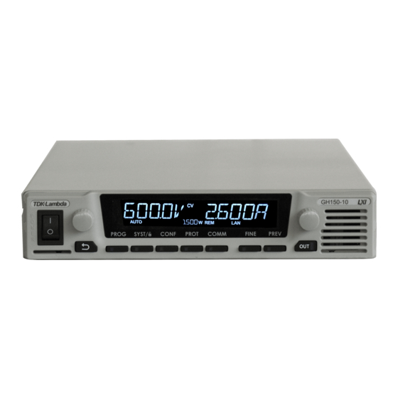
(including MODBUS-TCP and EtherCAT): https://www.emea.lambda.tdk.com/uk/technical-data/data.aspx?resource=Installation-Manuals Drivers and GUIs are updated periodically to support new features. Refer to TDK-Lambda Technical Centre web page for up-to-date drivers and GUIs: https://www.emea.lambda.tdk.com/uk/technical-centre/software-tools.aspx CHAPTER 1: FRONT/REAR PANEL CONTROL &... - Page 13 Figure 1–1: Front Panel Controls Control/Indicator Description Power Switch POWER ON/OFF control. Power Supply Model Model, Voltage & Current Identifier. Voltage Encoder and Encoder: A high-resolution detent rotary Encoder adjusting the output Button voltage and navigating menu. Button: An auxiliary function to accept the voltage-setting value in Preview mode.
- Page 14 Control/Indicator Description PROG Button / Indicator Activates the Program / Sequencer menu. The Program menu provides Sequencer function control, Trigger function control, and loads a sequence stored inside the power supply memory. Green LED lights when Program menu is active. If Program menu is active, press PROG button to exit to the main display.
- Page 15 Control/Indicator Description COMM Button / Indicator Activates the Communication menu. The Communication menu provides communication interface selection, power supply address selection, LAN settings control, communication baud- rate selection, communication language selection, and software revision information. Green LED lights when Communication menu is active. If Communication menu is active, press the COMM button to exit to the main menu.
-
Page 16: Front Panel Display And Indicators
Front Panel Display and Indicators Refer to Figure 1–2 and Table 1-2 for description of the Front Panel display and indicators. Figure 1–2: Front Panel Display and Indicators Control/Indicator Description Voltage Display 4-digit 16-segment Voltage display. Normally displays the output voltage. In preview mode, the display indicates the program setting of the output voltage. - Page 17 Control/Indicator Description Power / Address Indicator If power supply output is ON, actual output power is displayed. If power supply output is OFF, power supply address is displayed. * The address is displayed while Communication menu is active, regardless of the power supply output state. ext V / ext I Indicators External Voltage / External Current Analog Programming Indicators.
-
Page 18: Blank Front Panel
Blank Front Panel Refer to Figure 1–3 and Table 1-3 for description of the Blank Front Panel controls and Indicators. POWER Figure 1–3: Blank Front Panel Controls Connection Description Power Switch POWER ON/OFF control. Power Supply Model Model, Voltage & Current Identifier. Power LED Power supply ON/OFF status LED. -
Page 19: Rear Panel Connections And Controls
Rear Panel Connections and Controls Refer to Figure 1–4 and Table 1-4 for description of the Rear Panel connections and controls. Figure 1–4: Rear Panel Connection and Controls Connection Description AC Input Connector Connector type: 1kW 1-Phase: 6110.4310 SCHURTER (IEC C16). 1.5kW ~ 3.4kW 1-Phase: PC 5/ 3-G-7,62 PHOENIX CONTACT (shown). - Page 20 Connection Description 150V to 600V Connector type: GIC 2.5/ 4-G-7,62 PHOENIX CONTACT for Half-Rack models. IPC 5/ 4-GF-7,62 PHOENIX CONTACT for Full-Rack up to 5kW models. DFK-IPC 16/ 4-STF-10,16 PHOENIX CONTACT for 10kW ~ 15kW models. Remote Sense Connector A Connector for remote sensing connections. Connect to the load for regulation of the load voltage and compensation of load wire drop.
-
Page 21: J1 Connector Terminal And Function
Connection Description Isolated control and Isolated analog Control and monitoring signals, DB26HD type female, signals isolated from the output potential. Optional Interface Position for optional communication interface. Service Port Service port for factory use. USB interface connector, type B. Connector type: SAMTEC P/N: USBR-B-S-F-O-TH. - Page 22 Connection Description LOC/REM MON Output for indicating if the unit is in Local (digital) or Remote (analog) programming mode. LOC/REM SELECT Input for selecting between Local (digital) or Remote (analog) programming of the output Voltage and Current. IPGM Input for Remote (analog) voltage/resistance programming of the Output Current.
-
Page 23: Front Panel Display Messages
Front Panel Display Messages Table 1-6 shows the various messages shown on the display in different operating modes. Display Text Text Description Display Text Text Description OUTPUT LOCK LOCK ULOCK UNLOCK INTFC Interface SENSE SENSE RS232 RS232 LOCAL LOCAL RS485 RS485 REMOTE INTERLOCK... -
Page 24: Menu Navigation
Display Text Text Description Display Text Text Description PANEL PANEL TRIG TRIGGER E.VOL EXTERNAL VOLTAGE INIT INIT E.RES EXTERNAL RESISTANCE ABORT ABORT C.SRC CURRENT SOURCE LOAD LOAD RANGE RANGE TRG.IN TRIGGER INPUT R.INT INTERNAL RESISTANCE EXTERNAL C.PWR CONSTANT POWER POWER POWER CONT CONTINUES... - Page 25 COMMUNICATION MENU VOLTAGE CURRENT ENCODER ENCODER C O MM E N T E R - -- - -- - -- - -- - -- - -- - -- built_in - -- - -- - -- - -- - -- - -- - -- - -- option al - -- INTFC RS232...
- Page 26 PROTECTION MENU VOLTAGE CURRENT ENCODER ENCODER P R O T E N T E R 25.5 UVP.DL FOLD FOLD CC/CV FOLD 25.5 FLD.DL Fun ction (Voltage Disp lay) Lev el down E N T E R Par am eter (Cur re nt Dis play) Voltage e ncod er 1 step r otate Voltage e ncod er m ultiple steps rotate Cur re nt e ncod er 1 step r otate...
- Page 27 CONFIGURATION MENU VOLTAGE CURRENT ENCODER ENCODER C O N F E N T E R SAFE AUTO START PANEL E.VOL E.RES V.SRC R.SRC V.SRC PANEL E.VOL E.RES C.SRC RANGE R.INT R.INT R.INT 0.001 1.000 C.PWR C.POW C.POW POWER R.SRC V.SRC CURR VOLT SLEW...
- Page 28 SYSTEM MENU VOLTAGE CURRENT ENCODER ENCODER S Y S T/ E N T E R P resent mode LOCA L LOCK Note: Menu displays alternative P resent mode PANEL parameter only, no selection. RE MOTE / LOCK E D ULOCK SENSE LOCAL NORM...
-
Page 29: Exiting A Menu
PROGRAM MENU VOLTAGE CURRENT ENCODER ENCODER P R O G T R I G E N T E R A borted / No inita ilzed INIT Note: Menu displays alternative TRIG parameter only, no selection. Inita ilzed ABORT LOAD TRG.IN CONT 0.000 10.00... -
Page 30: Blank Front Panel (Gb Series) - Basic Operation
USB driver prior USB cable connection (USB drivers are available on TDK-Lambda Web-Site). To install USB driver, download it from TDK-Lambda Web- Site, decompress zipped file (if compressed), navigate to x86 folder for 32-bit operating system, or x64 folder for 64-bit operating system, launch dpinst.exe file. -
Page 31: Set Rs232 Communication Interface (Example)
2. *IDN? (query power supply for its identification string). Power supply replies its identification string (TDK-LAMBDA,G…), refer to section 4.13, *IDN? command for an example. NOTE Power supply ordered with an optional communication interface (i.e. IEEE, MODBUS TCP or EtherCAT) is configured, by default, to optional communication interface. Baud rate is set to 115200, SCPI communication language (unless optional interface requires unique language such as registers for MODBUS TCP or SDOs/PDOs for EtherCAT), address 6. -
Page 32: Set Gen Communication Language (Example)
NOTE Following SYST:ADDR 10, power supply is addressed as 10. To send commands to this supply, send INST:NSEL 10. 1.9.6 Set GEN Communication Language (Example) power supply default communication language is set to SCPI. Send the following commands to the power supply to set GEN language. 1. -
Page 33: Reset Blank Front Panel Power Supply To Default Settings
1. INST:NSEL 6 (power supply with address 6 will receive commands). 2. SYST:BAUD 9600 (switch baud rate to 9600). 3. SYST:INT RS232 (switch communication interface to RS232 interface). Update PC terminal software parameters as follows: Port: RS232, According to Device Manager (refer to Figure 1–11 for an example of COM5). Baud rate: 9600. -
Page 34: Chapter 2: Local Operation
CHAPTER 2: LOCAL OPERATION Introduction This Chapter describes the operating modes that do not require programming and monitoring the power supply via its communication interfaces: LAN, USB, RS232/RS485, Optional communication or by remote analog signals. Ensure that the REM indicator on the display is off (indicating Local mode). -
Page 35: Connecting Single Loads, Remote Sensing
2.2.2 Connecting Single Loads, Remote Sensing WARNING There is a potential shock hazard at the sense point when using power supply with an output voltage greater than 60VDC. Ensure that the connections at the load end are shielded to prevent accidental contact with hazardous voltages. -
Page 36: Connecting Multiple Loads, Radial Distribution Method
2.2.3 Connecting Multiple Loads, Radial Distribution Method Figure 2–3 shows multiple loads connected to one supply. Each load should be connected to the power supply’s output terminals using separate pairs of wires. It is recommended that each pair of wires will be as short as possible and twisted or shielded to minimize noise pick-up and radiation. Load lines, Twisted pairs, shortest length possible POWER... -
Page 37: Constant Voltage Mode And Voltage Setting
Constant Voltage Mode and Voltage Setting In Constant Voltage mode, the power supply regulates the output voltage at the selected value, while the load current varies as required by the load. While the power supply operates in Constant Voltage mode, the CV indicator on the display illuminates. -
Page 38: Constant Current Mode And Current Setting
Constant Current Mode and Current Setting In the Constant Current mode, the power supply regulates the output current at the selected value, while the voltage varies with the load requirement. While the power supply is operating in Constant Current mode, the CC indicator in the display illuminates. -
Page 39: Safe-Start And Auto-Restart Modes
Safe-Start and Auto-Restart Modes At AC turn on, the power supply can start at the last setting of the Output Voltage and Current limit with the output enabled (Auto-restart), or it can start with the output disabled (Safe mode). Press the Configuration button. Display shows START SAFE or START AUTO, depending on the currently selected start mode. -
Page 40: Over Voltage Protection
2.9.2 Over Voltage Protection The OVP circuit protects the load in the event of a remote or local programming error or a power supply failure. The protection circuit monitors the voltage at the power supply sense points thus providing the protection level at the load. Upon detection of an Over Voltage condition, the power supply output will shut down. -
Page 41: Activated Ovp Alarm
• AC recycle • On/Off recycle by analog control (Interlock/Enable) • Sending a communication command to enable output. 2.9.2.2 Activated OVP Alarm When the OVP is activated, the power supply output shuts down. The display shows OVP FAULT. RED alarm LED blinks 1/2Hz frequency. 2.9.3 Under Voltage Protection and Under Voltage Limit The UVL function prevents output voltage setting below the UVL set value, and prevents an... -
Page 42: Activated Uvp Alarm
Model Rated Output Minimum (V) Maximum (V) Voltage (V) 28.5 47.5 142.5 Table 2-2: UVL Programming Range 2.9.3.1 Activated UVP Alarm When the UVP is activated, the power supply output shuts down. The display shows UVP FAULT. RED alarm LED blinks 1/2Hz frequency. 2.9.4 Foldback Protection Foldback protection will shut down the power supply output if power supply operation mode... -
Page 43: Activated Fold Alarm
Press the Current encoder for selection of Foldback state. The display blinks once to acknowledge the setting. If the CC state is selected, the FOLD I indicator appears on the display. If the CV state is selected, the FOLD V indicator appears on the display. To turn off the Foldback protection, select FOLD OFF, following the same procedure above. -
Page 44: Ac Fail Alarm
2.9.7 AC Fail Alarm The AC Fail alarm indicates whether the AC input has been shut down or AC input is incorrect. When any of these faults occur, the display shows AC FAULT, Output power is disabled, and the alarm RED LED blinks 1/2 Hz frequency. Safe start mode: The power supply stays off after AC power returns. -
Page 45: Series Connection For Increased Output Voltage
WARNUNG Wenn Stromversorgungen in Reihe geschaltet sind und die Ausgangsklemmen potentialfrei sind (einschließlich den Lastklemmen), darf kein Anschluss ein größeres Spannungspotential gemäß der folgenden Definition aufweisen: Bei den Ausgangsmodellen von 10 ~ 100VDC: An den Anschlüssen darf kein größeres Potential von bis zu +/- 200VDC gegen Erde haben. -
Page 46: Remote Programming In Series Operation
POWER SUPPLY COM. LOAD (**) POWER SUPPLY Figure 2–6: Series Connection for Positive/Negative Output Voltages (*) Diodes are user supplied. (**) Optional ground connection. 2.10.3 Remote Programming in Series Operation Programming by external voltage: The analog programming circuits of this power supply are isolated from the output potentials. -
Page 47: Daisy-Chain Connection
2.11 Daisy-Chain Connection It is possible to configure a multiple power supply system to shut down all units when a fault condition occurs in one of the units. When the fault is removed, the system recovers according to a preset state: Safe start mode or Auto-restart mode. If a fault occurs in one of the units, its ”Daisy out”... -
Page 48: Rear Panel (J1 Connector) Functions
SO signal level Power Supply Output DAISY_Out Level PS_OK Level (J1-2 – J1-11) (J1-3 – J1-11) (J1-1 – J1-11) 2-30V or Open High 0-0.6V or Short Off (SO FAULT) High (Open Collector) Table 2-3: Daisy_In Signal Definition 2.12 Rear Panel (J1 Connector) Functions 2.12.1 Interlock Function - Analog On/Off (Enable/Disable) Interlock signal (\ILC_IN) serves as power supply output enable control via a switch or relay. -
Page 49: Activated Ilc Alarm
2.12.1.1 Activated ILC Alarm When the ILC is activated, the power supply output shuts down. The display shows ILC FAULT. RED alarm LED blinks 1/2Hz frequency. 2.12.2 Enable In Function ENA_IN signal serves as power supply output enable control. Connection to the signal is made via pin J1-10 (ENA_IN) and pin J1-11 (COM_SELV), which are isolated from the power supply output. -
Page 50: Auxiliary Programmed Signals Prog_Out_1 And Prog_Out_2
Alarm LED Front Panel ENA Polarity ENA Input Power Supply Display ENA Setting Output OFF – Default Open or Short Voltage/Current NORM Open Or 2~30V Off ENA FAULT NORM Short Or 0~0.6V On Voltage/Current Open Or 2~30V On Voltage/Current Short Or 0~0.6V Off ENA FAULT Table 2-5: Enable Functions and Settings 2.12.4... -
Page 51: Cv/Cc Signal
PS_OK delay setting: Press SYST Button, SYST (GREEN) LED illuminates. Rotate Voltage encoder until PSO.DL Appears. Rotate the Current encoder to set the required delay time. Press on the current encoder to select the desired delay value. The display will blink once to acknowledge the setting. Exit SYST menu by pressing the Back button or the SYST button. -
Page 52: Reset
NOTES 1. If FRST function is performed by communication command, power supply loses communication due to communication settings change and addressing is lost. Firmware 02.106 and above has the ability to select communication interface following factory reset operation. Refer to section 4.14.10, SYSTem:FRST <DSC> command. 2. - Page 53 Function Factory Reset Reset Last Save & Recall Setting (Default Settings) Power Supply Start Mode SAFE SAFE Power Supply Output State Voltage Set Point [V] Current Set Point [A] 1.05 * RATED Over Voltage Protection (OVP) [V] 1.1 * RATED 1.1 * RATED or 1.2 * RATED or 1.2 * RATED...
- Page 54 Function Factory Reset (Default Settings) IP Address DHCP configuration DHCP Ping server Enabled Auto-Negotiation Enabled Description (Service Name) TDK-LAMBDA Supply <last 3 serial number digits> Password Clear field (None) Hostname G[H]<rated voltage>-<rated current> VXI-11 Discovery Enabled Keep-Alive Time [S] 1800 mDNS &...
-
Page 55: Chapter 3: Remote Analog Programming
CHAPTER 3: REMOTE ANALOG PROGRAMMING Introduction The Rear Panel connector J1 allows the user to program the power supply output voltage and current with an analog device. J1 also provides monitoring signals for output voltage and output current. The programming range and monitoring signals range can be selected between 0-5V or 0- 10V using the Front Panel menu or communication. -
Page 56: Remote Voltage Programming Of Output Voltage And Current
Remote Voltage Programming of Output Voltage and Current For Voltage Analog Programming wiring, refer to Figure 3–1. Set the Remote Programming settings as follows: Short the pin J1-6 to J1-11. Press the CONF button. CONF (GREEN) LED illuminates. Rotate the Voltage encoder until V.SRC or C.SRC appears on the voltage display. Rotate the Current encoder to set E.VOL. -
Page 57: Remote Resistor Programming Of Output Voltage And Output Current
Remote Resistor Programming of Output Voltage and Output Current For resistive programming, the internal current sources for output voltage and/or output current control, supply 1mA current through external programming resistors connected between J1-8 and J1-18 and between J1-7 and J1-18. The outcome voltage, as a result, of current flow across the programming resistors is used as a programming voltage for the power supply. -
Page 58: Monitoring Of Output Voltage (V_Mon) And Current (I_Mon)
NOTES 1. The power supply can be programmed to up to 108% of the rated output voltage and current. However, it is forbidden to operate the power supply over its voltage and current ratings. Performance is not guaranteed when operating the power supply above its ratings. 2. -
Page 59: Serial Rs232/Rs485, Usb & Lan Interfaces
CHAPTER 4: SERIAL RS232/RS485, USB & LAN INTERFACES Introduction This chapter describes the set-up, operation, commands, and communication protocols of the power supplies via serial communication interfaces: RS232, RS485, or USB, and LAN. Configuration Function Level Display Parameter Level Display Description RS232 RS232... -
Page 60: Address Setting
4.2.3 Address Setting The power supply address can be set to any address in the range of 0 to 31. Press the COMM button. COMM LED illuminates. INTFC message appears on the Voltage display. Rotate the Voltage encoder 1 step clockwise. ADR message appears on the Voltage display. -
Page 61: Baud Rate Setting
4.2.5 Baud Rate Setting Five optional rates are possible: 9600, 19200, 38400, 57600 and 115200. Press the COMM button. COMM LED illuminates. INTFC message appears on the Voltage display. Rotate the Voltage encoder 2 steps clockwise *. BAUD message appears on the Voltage display. Rotate the Current encoder to select required baud rate: 9600, 19200, 38400, 57600 or 115200 **. -
Page 62: Setting Unit In Remote, Local Lockout Or Local Mode
4.2.7 Setting Unit in Remote, Local Lockout or Local Mode If power supply is in Local mode, it can receive communication commands & queries. If a command is received, power supply will execute and change its mode to Remote. If a query is received, power supply will reply and remain in the Local mode. -
Page 63: Rear Panel Rs232/Rs485 In Connector
Rear Panel RS232/RS485 IN Connector RS232/485 in the interface is accessible through the rear panel RS232/485 IN connector. The connector is eight contacts, shielded RJ-45 type. The connector is used to connect power supplies in RS232 or RS485 configurations. Refer to Figure 4–1 for the connector description. Shield (Connector enclosure) 1 2 3 4 5 6 7 8... -
Page 64: Rear Panel Rs485 Out Connector
Rear Panel RS485 OUT Connector RS485 OUT interface is accessible through the Rear panel RS485 OUT connector. The connector is eight contacts, shielded RJ-45 type. The connector is used to connect power supplies in RS485 Daisy chain configuration. Refer to Figure 4–2 for the connector description. Shield (Connector enclosure) 1 2 3 4 5 6 7 8... -
Page 65: Connecting Power Supply To Rs232 Or Rs485 Bus
Connecting Power Supply to RS232 or RS485 BUS Connect rear panel RS232/RS485 IN connector to the controller, or a PC RS232 or RS485 port using a suitable shielded cable. Refer to Figure 4–3 and Figure 4–4 for the available RS232 and RS485 cables. -
Page 66: Rear Panel Usb Connector
USB port Figure 4–6: USB Connection To install USB driver, download it from TDK-Lambda Web-Site, decompress zipped file (if compressed), navigate to x86 folder for 32-bit operating system, or x64 folder for 64-bit operating system, launch dpinst.exe file. Follow on-screen instructions to accomplish the installation process (refer to Applications Guide, IA761-04-03_ for step-by-step installation procedure). -
Page 67: Rear Panel Lan
Rear Panel LAN 4.7.1 Introduction The Local Area Network (LAN) connection for the power supply series allows the user to remotely program, measure and check status of the power supply. A computer web page browser can be used to operate the power supply through a built-in web page server. -
Page 68: Specifications
Selects fastest of 10Base-T or 100Base-T networks (10 or 100 Megabits per second) NETWORK CONFIGURATION MAC Address TDK-Lambda assigned: 00:19:f9:xx:xx:xx xx:xx:xx is the unique address for each unit IP Address View or set from the Front Panel or embedded web page DHCP Receive an address from network server. - Page 69 Multiple web pages can be open at the same time Identity Identify power supply model, serial number, revision, etc. View and set LAN configuration Configuration Active Control Program and read output settings Send Send SCPI commands, read errors Commands Help Link to TDK-Lambda web sites...
-
Page 70: Lan Command Speed
SUPPLY CONFIGURATIONS Local Control Supply may be controlled from the Front Panel even if LAN is monitoring LAN Remote Control Supply may be controlled and monitored through LAN RS232, RS485, USB LAN interface is disabled if the standard RS-232, RS-485, USB or or Option Control Optional communications are active Analog Control... -
Page 71: Select The Control Method
4.7.3 Select the Control Method 4.7.3.1 Control Method Options The power supply with may be operated through four interfaces. This section describes how to enable each option. MODE MODE DESCRIPTION Control using an Ethernet connection LAN disables serial and optional communication ports Local Control using the front panel encoders... -
Page 72: Connect To A Network
Duplicate IP: Blinking green • If there are two (or more) instruments with the same IP address, green led is blinking. • LAN Fault/Disconnected: Steady red Shows that the LAN interface is not selected, LAN connection is disconnected or broken. 4.7.4 Connect to a Network 4.7.4.1... -
Page 73: Power-Up The Lan Power Supply
• PEER-TO-PEER NETWORK In this type of configuration, the power supply is connected directly to a computer that is not a network server. The power supply configures its own IP address and other settings. Figure 4–8: Peer-to-Peer Network 4.7.4.3 Power-up the LAN Power Supply The power supply LAN option automatically detects if it is connected or disconnected from a network. -
Page 74: Ip Addresses
4.7.4.4 IP Addresses The simplest and most reliable way to open a network connection is via the power supply’s IP address, which is represented by a group of four numbers separated by periods (i.e. 10.1.15.123). The power supply can receive an IP address in three modes: DHCP Auto-IP Static IP... -
Page 75: Description And Dns Service Names
This is called a service name conflict. In this case, the supply will change its service name to a unique name by appending a number in brackets to it. For example, its service name will become TDK-LAMBDA Supply 123 (2). -
Page 76: Lan Setup
A LAN Reset does not change the service name, even if it is a custom name, but it may remove the dash and the number if a service name conflict has been removed. To restore the factory default service name, open the LAN Modify web page and enter a blank for the new service name (refer to section 4.7.6.6). -
Page 77: Lan Reset
To change the IP address: Press COMM button. Rotate Voltage Encoder until IP appears on the Voltage display, 1 appears on the Current display. Press Current encoder to enter IP configuration. Rotate Voltage encoder to view the IP address. Voltage display shows IP1-IP4 by rotating Voltage encoder. The Current display shows the corresponding IP address. -
Page 78: Web
Keep-Alive: 1800 Seconds (30 minutes) Auto-Negotiate: Automatically select network speed VXI-11 Discovery: Enabled Password: None Multicast DNS: Enabled 4.7.6 Web Pages 4.7.6.1 Benefits of Web Pages web pages are useful for: Reading the power supply model, identity, revision and LAN setup information •... -
Page 79: The Home Page
4.7.6.3 The Home Page The following page appears when the web page is opened for the first time or when it is refreshed: Figure 4–9: Home Page VISA Name Using IP Address For automation programming, VISA is a type of communication driver. For LAN instruments, the IP address may be used in the VISA resource descriptor. -
Page 80: Login Rules
Auto-Negotiate Power supply LAN automatically adjusts its speed to the fastest speed available. Multicast DNS The LAN broadcasts its hostname even if no network server is present. This is useful for connecting over simple peer-to-peer networks. Logging In To change power supply output or LAN settings, a user must first log in. When the DC Power tab or LAN tab is clicked, a login box appears: Click the Login button at the bottom-left side of the web page. -
Page 81: Dc Power Page
4.7.6.5 DC Power Page When the DC Power tab is selected, the following web page opens. This page and its sub-menus allow a user to operate the power supply and adjust its output settings. A. DC Power ➔ Output Page When the DC Power tab is selected, the Output page opens by default (GUI). - Page 82 Settings This section displays the selected power supply’s output voltage, current limit and output ON/OFF settings. The settings cannot be changed until you have logged-in as 'admin'. To change a settings, perform the following: Tick Check to Modify. Set desired settings. After settings are made, click Apply. To view the actual settings, deselect Check to Modify.
- Page 83 C. DC Power ➔ System Page On the DC Power tab, the System button is available at the top of the panel. When opened, the window allows the user to operate four functions: • Reset One Instrument (this resets only the supply selected in the RS-485 list box). •...
-
Page 84: Lan Page
• Hostname The power supply hostname may be used instead of the IP address to create a communication link. • Description By default, this is “TDK-LAMBDA Supply <Last 3 digits of the Serial Number>”, but it may be changed. - Page 85 • Controller Access The “One Client Only” setting is the default setting for the highest networking security. This setting allows only one TCP socket to be open at a time, it disables the connectionless UDP sockets. The multiple client setting is needed to allow more than one controller connection at a time and to enable UDP sockets connections.
- Page 86 Therefore, these fields are disabled (gray) on the web page. If the server cannot make the assignment, the power supply reverts to the Auto IP method, described in section 4.7.4.4 on page 63. In this mode, the user can change the hostname and description only. NOTE The Hostname must not exceed 15 characters.
- Page 87 • LAN Timeout If the user is logged in via the web page or by using VISA or TCP sockets, this is the time duration (in seconds) in which the web pages may be inactive (idle) before the power supply automatically logs out.
-
Page 88: Help Page
Figure 4–19: LAN – Users Tab 4.7.6.7 HELP Page A Help tab is available. This page is an Internet link to TDK-Lambda’s website pages. Figure 4–20: Help Tab 4.7.7 Programming Using VISA Drivers 4.7.7.1 VISA Description In the test and measurement industry, Virtual Instrument Software Architecture (VISA) is a popular framework that includes hardware drivers, configuration utilities and connection managers. -
Page 89: Opening A Visa Connection
4.7.7.3 Opening a VISA Connection Test and automation programs may easily be written if they use the VISA libraries. The supported VISA functions include Open, Read, Write and Close. A VISA resource descriptor is used to describe a particular supply. For the power supply, the descriptors are found on the supply’s Home web page. -
Page 90: Input Buffer Requirements
NOTE The performance of the LAN interface is impacted as more web pages, ports and sockets are open at the same time. No more than two pages are open at the same time. The rules for the One Client/Multiple Clients are: One Client Only Multiple Clients Web Page Not logged-in... -
Page 91: Using Tcp Sockets
Terminator Character (and ASCII hex) One or more terminators required: Line-feed, Carriage-return Commands from the Controller 0x0A 0x0D Responses from the All responses have Line-Feed and Carriage-return 0x0D and 0x0A 4.7.8.6 Using TCP Sockets This is the most commonly used socket type. It features a managed connection, message acknowledgements, transmission error detection and correction. -
Page 92: Multi Power Supply Connection (Daisy-Chain) To Rs232, Rs485, Usb Or Lan
Multi Power Supply Connection (Daisy-Chain) to RS232, RS485, USB or LAN A Daisy-chain configuration of up to 32 units can be connected to RS232, RS485, USB, LAN or optional communication (i.e. IEEE or MODBUS TCP). The first unit connects to the controller or PC via RS232, RS485, USB, LAN or optional communication, while the RS485 bus connects the other units. - Page 93 NOTE If a custom cable is used, connect only the pins listed in the table above. Keep pins 1, 2 and 7 not connected. CAUTION When using multiple LAN controllers with Multi-drop, only one power supply may be “selected” at a time because one controller may change the selected address and the others may not be aware that a new address is active.
-
Page 94: Gen Protocol (Gen Series Communication Language)
NOTE RS-485 retransmit baud-rate is automatically set to 115,200 bps if USB, LAN or optional communication (i.e. IEEE or MODBUS TCP) is selected. GEN Protocol (GEN series communication language) GEN communication language is supported to provide compatibility to the legacy GENESYS Programmable Power Supplies Series. -
Page 95: Acknowledge
4.9.5 Acknowledge The power supply acknowledges the commands received by returning an ”OK” message. If an error is detected, the power supply returns an error message. The rules for the checksum apply to the Acknowledge feature as well. 4.9.6 Backspace The backspace character (ASCII 8) clears the last character sent to the power supply. -
Page 96: Identification Commands
4.10.4 Identification Commands IDN? Query Returns the power supply model identification as an ASCII string (one comma, no spaces) Returns <SRD> Example TDK-LAMBDA,G100-50 REV? Query Returns the software version as an ASCII string Returns <SRD> Example G:XX.XXX Query Returns the supply’s serial number. Up to 12 characters in any format Returns <SRD>... -
Page 97: Output Commands
Function Reset setting. Refer to Table 2-6. Returns <DSC> OK Function Repeat last command. If \<CR> is received, the power supply will repeat the last command Returns <DSC> OK FRST Function Restore factory reset parameters. Refer to Table 2-6 & Table 2-7 Returns None NOTES... - Page 98 Query Returns the measured output power Returns <NR2> 5 digits format DVC? Query Displays Voltage and Current data. Data returns as a string of ASCII characters. A comma separates different fields. Fields order: Measured Voltage, Programmed Voltage, Measured Current, Programmed Current, Over Voltage Set Point and Under Voltage Set Point Example 10.000, 10.000, 020.02, 010.00, 040.5, 000.0...
- Page 99 OVP <NR2> Function Sets the Over-Voltage Protection level. An attempt to adjust the OVP level below voltage setting level will result in the execution error response (‘E04’) and the OVP setting will stay unchanged. Parameters OVP programming range is limited by: 5% above voltage setting.
-
Page 100: Global Output Commands
RCL <NR1> Function Restores the power supply settings from a stored memory location (locations 1, 2, 3 or 4), previously stored by the SAV command Parameters 1,2,3,4. RCL without a parameter restores the power supply settings stored in the memory location 1 MODE? Query Returns the power supply operation mode. - Page 101 GSAV <NR1> Function Refer to SAV command description. Parameters 1,2,3,4 Returns No reply GPC <NR2> Function Refer to PC command description. Returns No reply GOUT <Bool> Function Refer to OUT command description. Parameter 0|1, OFF|ON Returns No reply GPV <NR2> Function Refer to PV command description.
- Page 102 Model Maximum Model Maximum Model Maximum Model Maximum Model Maximum 1.5kW 1.7kW 2.7kW 3.4kW 10-100 10-150 10-170 10-265 10-340 20-50 20-75 20-85 20-135 20-170 30-34 30-50 30-56 30-90 30-112 40-25 40-38 40-42 40-68 40-85 60-17 60-25 60-28 60-45 60-56 80-12.5 12.5 80-19 80-21...
-
Page 103: Auxiliary Commands
4.10.8 Auxiliary Commands BOOL <DSC> Function Select query Return format of Boolean (<Bool>) commands. DIGIT – Boolean queries are replied with 0|1. TEXT – Boolean queries are replied with OFF|ON. Parameters DIGIT|TEXT, 0|1 Query BOOL? Returns <DSC> DIGIT|TEXT NOTE BOOL <DSC> command is available from firmware revision 02.110. LANG <DSC>... -
Page 104: Status Commands
APR <DSC> Function Set the power supply analog programming & monitoring range. Programming – 5/10 volt or 5/10kΩ. Monitoring – 5/10 volt Parameters 5|10 Query APR? Returns <DSC> 5|10 REL1 <Bool> Function Set the Programmable Pin 1 state (J1.21). 0 – MOSFET ON. 1 – MOSFET OFF. Parameter 0|1, OFF|ON Query... - Page 105 FEVE? Query Returns the value of the Questionable Group Event register, which is a read-only register. Fault Events are updated as a transition from 0 to 1. Reading the register clears it (All Zeros). Returns <NRh> STAT? Query Returns the value of the Operation Group Condition register, which is a read- only register that holds the real-time status of the power supply.
-
Page 106: Serial Communication Test Set-Up
4.11 Serial Communication Test Set-Up Basic set-up to test serial communication operation. Equipment PC with a serial communication terminal software installed, power supply and RS232 or USB cable. PC Set-up Bits per second: 115200 Data bits: 8 Parity: None Stop bits: 1 Flow control: None Power Supply Set-up Connect power supply to the PC using RS232 or USB cable. -
Page 107: Scpi Protocol
4.12 SCPI Protocol Recommended time delay between commands: 5mSec minimum. Some commands might require longer time. In such cases, refer to NOTE following command description. NOTE Selecting the power supply (INSTrument:NSELect <address>) is necessary before using any other command. 4.12.1 Data Format Serial data format is 8 bit, one start bit and one stop bit. -
Page 108: Scpi Command Hierarchy
4.12.5 SCPI Command Hierarchy SCPI is an ASCII-based command language designed for use in test and measurement equipment. The command structure is organized around common roots, or nodes, which are the building blocks of the SCPI subsystems. An example of a common root is OUTPut. Some of the commands that reside in the OUTPut subsystem are: OUTPut [:STATe] <bool>... -
Page 109: Commands Notes
Data Description Formats <DSC> DiSCrete. Discrete parameters are used to program settings that have a limited number of values (i.e. TRIGger:SOURce {BUS|EXTernal}). Discrete parameters have a short form and a long form, just like command keywords. One can mix upper-case and lower-case letters. Query responses will always return the short form in all upper-case letters. - Page 110 *ESE <NR1> Function This command programs the Standard Event Status Enable register bits. The programming determines which events of the Standard Event Status Event register (see *ESR? below) are allowed to set the ESB (Event Summary Bit) of the Status Byte register. "1"...
- Page 111 The string includes manufacturer, model number, type of installed option, serial number and Interface firmware revision. Returns <SRD> Example TDK-LAMBDA,GH100-50-GPIB,12345-123456,G:01.000 *OPC Function Sets Operation Complete (bit 0) in the Standard Event Status Event Register at the completion of the current operation.
- Page 112 *OPT? Query Returns the type of an optional card installed. Returns <SRD> 0,No Option Installed 1,GPIB 2,MODBUS 3,ETHERCAT *PSC <Bool> Function The Power ON Status Clear (PSC) command controls automatic Power ON clear of the Service Request Enable Register, the Standard Event Status Enable Register, and Device Specific Event Enable registers.
- Page 113 *SRE <NR1> Function Sets the condition of the Service Request Enable Register. This register determines which bits from the Status Byte Register are allowed to set the Request for Service (RQS) summary bit. A "1" in any Service Request Enable Register bit position enables the corresponding Status Byte Register bit. All such enabled bits are logically OR-ed to determine the Status Byte Register, RQS bit state.
-
Page 114: Scpi Subsystem Commands
*TST? Query Self-test query. If one or more tests fail, "1" is returned. Error is stored in the error queue. Returns <Bool> 0|1 *WAI Function Configures the instrument to wait for all pending operations to complete before executing any additional commands over the interface. ABORt Function This command cancels any sequencer actions in progress. -
Page 115: Initiate Subsystem
4.14.2 Initiate Subsystem INITiate[:IMMediate] Function Initialize trigger system. If initialized, trigger in system is active (system is ready to receive trigger signal). If not initialized, all trigger signals are ignored. INITiate:CONTinuous <Bool> Function Continuously re-initiates a trigger. If inactive, the trigger system must be re-initiated for each trigger by the INITiate command. -
Page 116: Global Subsystem
4.14.4 Global Subsystem Global Commands General Power Supplies acting upon Global Commands don’t have to be addressed. • • All Power Supplies attached to the Interface must be capable of accepting Global Commands. • Global commands have no reply, execution only. GLOBal:*RCL <NR1>... -
Page 117: Output Subsystem
4.14.6 Output Subsystem OUTPut[:STATe] <Bool> Function Enables / Disables the power supply output Setting. Query returns an actual output status. Parameter 0|1, OFF|ON Query OUTPut[:STATe]? Return <Bool> 0|1 OUTPut:ENA[:STATe] <Bool> Function Enables / Disables the ENA function. If disabled, power supply ignores the ENA pin signal (J1-10). Parameter 0|1, OFF|ON Query... - Page 118 OUTPut:PON[:STATe] <DSC> Function Determines the power supply output state after the AC recovery or non- latching (OTP, ILC, ENA, DAISY_IN) faults. SAFE – Power supply output recovers to off state. AUTO – Power supply output recovers to prior failure state. Parameter 0|1, OFF|ON, SAFE|AUTO Query...
-
Page 119: Program Subsystem
OUTPut:RELay2[:STATe] <Bool> Function Sets PROG_OUT_2 pin (J1-20) in a rear panel connector. 0 – MOSFET is ON. 1 – MOSFET is OFF. Parameter 0|1, OFF|ON Query OUTPut:RELay2[:STATe]? Return <Bool> 0|1 OUTPut:TTLTrg:MODE <DSC> Sets the operation mode of the Trigger Out signal to OFF, FSTR, or TRIG Function mode. - Page 120 [PROGram]:LIST:DWELl <NRf+>,{<NRf+>} Function: Specifies the time interval of each value (point) in a list to remain in effect. The function accepts up to 100 parameters. Parameters 0.001 to 129,600 Unit Query [PROGram]:LIST:DWELl? Return <NR2>,{<NR2>} Example LIST:DWEL .6,1.5,1.5,.4 NOTE A delay of ~100mSec is required after the [PROGram]:LIST:DWELl command if long sequences are used, prior sending any additional command.
- Page 121 NOTES Delay of ~20mSec is required after a LOAD command, prior to sending any additional command. UVL and OVP level settings clamp sequence-programmed values. Loading an empty sequence results in error -286,”Data Load Empty”. Loading a sequence while any sequence is running, results in error -284,”Program Currently Running”.
- Page 122 [PROGram]:WAVE:TIME <NRf+>,{<NRf+>} Function: Specifies the time interval of each slope between 2 points of a WAVE. The function defines up to 100 parameters. Parameters 0.001 to 129,600 seconds. Default: 0.001s Unit Query [PROGram]:WAVE:TIME? Return <NR2>,{<NR2>} Example WAVE:TIME .6,1.5,1.5,.4 NOTE A delay of ~100mSec is required after the [PROGram]:WAVE:TIME command if long sequences are used, prior sending any additional command.
-
Page 123: Source Subsystem
4.14.8 Source Subsystem [SOURce]:CURRent:EXTernal:LIMit[:STATe] <Bool> Function Enables/disables the current limit in the analog source control mode. If enabled, the analog current programming range by the rear panel is limited to a digital current programming value. Refer to section 5.7 for additional information explaining OCL – Analog Programming Over Current Limit. - Page 124 [SOURce]:CURRent:SLEW:UP <NRf+> Function Sets a digital current reference up programming slew rate. Parameters 0.0001 ~ 999.99 Unit A/mS Query [SOURce]:CURRent:SLEW:UP? Return <NR2> Example :CURR:SLEW:UP 1 Sets a digital current reference up programming slew to 1A/mSec. :CURR:SLEW:UP? returns a digital current up programming slope value. :CURR:SLEW:UP? MAX and :CURR:SLEW:UP? MIN return the maximum and minimum digital current reference up programming slope value.
- Page 125 [SOURce]:VOLTage:SLEW:DOWN <NRf+> Function Sets a digital voltage reference down programming slew rate. Parameters 0.0001 ~ 999.99 Unit V/mS Query [SOURce]:VOLTage:SLEW:DOWN? Return <NR2> Example :VOLT:SLEW:DOWN 1 Sets a digital voltage reference down programming slew to 1V/mSec. :VOLT:SLEW:DOWN? returns a digital voltage down programming slope value.
- Page 126 NOTE Minimum value is limited to 5% above the actual voltage setting value [SOURce]:VOLTage:PROTection:LOW:DELay <NRf+> Function Sets the time delay between UVP fault event and output disable. Parameters 0.1 ~ 25.5|MIN|MAX. Resolution: 0.1 Note: Round input parameter to closest 100mSec step. Unit Query [SOURce]:VOLTage:PROTection:LOW:DELay?
- Page 127 [SOURce]:POWer:STATe <Bool> Function Enables/Disables the constant power limit mode. Parameters 0|1, OFF|ON Query [SOURce]:POWer:STATe? Return <Bool> 0|1 NOTE Analog programming, internal resistance, sequencer and Slew-Rate functions should be disabled to enable Constant Power. [SOURce]:POWer[:LEVel] <NRf+> Function Sets the constant power limit level. Parameters The range is limited to a multiplication of maximum voltage by maximum current rating values.
-
Page 128: Status Subsystem
4.14.9 STATus Subsystem STATus:OPERation[:EVENt]? Query Returns the value of the Operational Condition Group Event register. The value is according to the Operational Condition Group Condition register and Operational Condition Group Enable register. The Event register is a read-only register. Events are updated as transition from 0 to 1. Reading the register clears it. Bit configuration of the Operational Condition Group Event register is as follows: Position Value... - Page 129 STATus:OPERation:CONDition? Query Returns the value of the Operational Condition Group Condition register, which is a read-only register that holds the real-time operational status of the power supply. Refer to STATus:OPERation[:EVENt]? command for the complete registers list. Returns <NR1> 0…65535 Example 00136 STATus:OPERation:ENABle <NR1>...
- Page 130 STATus:QUEStionable[:EVENt]? Query Returns the value of the Questionable Condition Group Event register. This is a read- only register. The value is according to the Questionable Condition Group Condition register and Questionable Condition Group Enable register. Events are updated as transition from 0 to 1. Reading the register clears it. Bit configuration of the Questionable Condition Group Event register is as follows: Position 2048...
-
Page 131: System Subsystem
STATus:QUEStionable:CONDition? Query Returns the value of the Questionable Condition Group Condition register, which is a read-only register that holds the real-time conditional status of the power supply. Refer to STATus:QUEStionable[:EVENt]? command for the complete registers list. Returns <NR1> 0…65535 Example 00136 STATus:QUEStionable:ENABle <NR1>... - Page 132 NOTE SYSTem[:COMMunicate]:BOOL[:STATe] <DSC> command is available from firmware revision 02.110. SYSTem[:COMMunicate]:INTerface <DSC> Function Sets a communication interface. Power supply addressing is lost after communication interface change. Parameters 0|1|2|3|4, RS232|RS485|LAN|USB|OPTion Query SYSTem[:COMMunicate]:INTerface? Return <DSC> RS232, RS485, LAN, USB, OPT NOTE Execution time for this command is ~25mS SYSTem[:COMMunicate]:LAN:HOST? Query Reads hostname.
- Page 133 SYSTem[:COMMunicate]:LANGuage <DSC> Function Sets the communication protocol to GEN language. GEN language is available in RS232/485 and USB. Parameter Query SYSTem[:COMMunicate]:LANGuage? Return <DSC> SCPI NOTE SYSTem[:COMMunicate]:LANGuage GEN command returns -220 “Parameter Error” to SYSTem:ERRor? query if sent via LAN or optional communication interface. LAN or optional communication interfaces do not support GEN language.
- Page 134 SYSTem:FRST <DSC> Function Restores factory default parameters and sets communication interface according to <DSC> parameter. Refer to Table 2-6 & Table 2-7. Parameters 1|2|3|4|5, USB|RS232|RS485|LAN|OPTion SYSTem:FRST without a parameter sets USB communication interface. NOTES 1. Factory Reset does not affect advanced parallel configuration acknowledgment (does not affect power supply configuration (Single, Master or Slave roles does not change).
- Page 135 SYSTem:PON:TIME:AC? Query Returns the total time power supply is connected to AC. Max value: 2 Unit minutes Return <NR1> SYSTem:PRELoad[:STATe] <Bool> Function Enables / Disables Preload. If disabled, preload is deactivated 5 seconds after DC output off. Parameters 0|1, OFF|ON Query SYSTem:PRELoad[:STATe]? Return...
- Page 136 SYSTem:RIN:STATe <Bool> Function Enables / Disables the internal resistance function. Parameters 0|1, OFF|ON Query SYSTem:RIN:STATe? Return <Bool> 0|1 NOTE The Internal Resistance function can be set to ON only if the Sequencer, Constant Power Limit, Analog Programming and Slew-Rate modes are disabled. SYSTem:REMote[:STATe] <DSC>...
-
Page 137: Trigger Subsystem
SYSTem:TEMPerature[:AMBient]? Query Returns ambient temperature Unit ºC Return <NR1> Example SYSTem:VERSion? Query Returns SCPI language version Return <SRD> 1999.0 4.14.11 TRIGger Subsystem NOTE The Trigger subsystem must be enabled from the Initiate subsystem. If disabled, commands from the trigger subsystem will not affect power supply output. TRIGger[:IMMediate] Function If Trigger is enabled (by INITiate command), TRIG generates an... -
Page 138: Scpi Commands Summary
4.15 SCPI Commands Summary Com m on Com m ands Description SCPI Command *CLS Clear standard event status register *ESE <NR1> (?) Set standard event status enable <NC> register *ESR? Return standard event status event <NC> register *IDN? Return instrument identification string IDN? *OPC (?) Set "operation complete"... - Page 139 :PROTection :CLEar Protection clear <NC> :FOLDback [:MODE] <DSC> (?) Set operation protection mode FLD(?) :DELay <NRf+> (?) Set foldback delay FBD(?) :RELay {1|2} [:STATe] <Bool> (?) Set control pins status {1|2}(?) :TTLTrg :MODE <DSC> (?) Set output trigger mode <NC> [:][PROGram] :COUNter <NR1>,INFinity (?) Set number of iterations...
- Page 140 :CONDition? Returns the value of the Condition FLT? register :ENABle <NR1> (?) Enables specific bits in the Event FENA(?) register [:]SYSTem [:COMMunicate] :ADDRess <NR1> (?) Set communication address <NC> :BAUDrate <DSC> (?) Set Baud rate <NC> :BOOL <NR1> (?) Set Boolean commands return type BOOL :INTerface <DSC>...
-
Page 141: Chapter 5: Advanced Functions
CHAPTER 5: ADVANCED FUNCTIONS Sequencer The sequencer allows advanced waveforms programming of power supply output in steps of one mille-second. Up to four sequences, 100 points each, can be stored inside power supply memory. There are two programmable modes: LIST and WAVE. These programmable modes are synchronized by input trigger (refer to section 5.2.2). -
Page 142: Wave Mode
0.01s ec Tri gger Ini ti a ted INIT:IMM Tri gger Wa i t Tri gger Event Tri gger Del a y 0.02s TRIG:DEL 0.02 Dwel l 0.05s 0.06s 0.03s LIST:DWELL 0.05,0.06,0.03 OUTPUT LIST:VOLT 5,10,0 VOLTAGE STEP AUTO Figure 5–2: LIST Mode Sequence Example 5.1.2 WAVE Mode Output value change in slopes is determined by parameters in the WAVE. -
Page 143: Sequencer Functions
0.01s ec Tri g Ini ta ted INIT:IMM Tri gger Wa i t Tri gger Event Tri gger Del a y 0.02s TRIG:DEL 0.02 Ti me 0.03s 0.02s 0.03s 0.03s 0.02s 0.03s WAVE:TIME 0.03,0.02,0.03 WAVE:VOLT 10,10,0 OUTPUT VOLTAGE COUN 2 INIT:CONT 0 STEP AUTO Figure 5–4: WAVE Mode Sequence Example... -
Page 144: Step
5.1.3.6 Step Execute a single step from a sequence in the LIST or WAVE mode. Step function is available via the communication command [PROGram]:STEP <DSC>. 5.1.3.7 Continuous Continuous flag provides the ability to skip the IDLE STATE (refer to Figure 5–1 and/or Figure 5–2) after a sequence has completed. -
Page 145: Sequencer Setting Memory
NOTE If the Sequencer function is enabled (INITIATE STATE), the Internal Resistance, Constant Power Limit, Slew-Rate and Analog Programming functions are disabled. NOTE If the Internal Resistance, Constant Power Limit, Slew-Rate or Analog Programming functions are enabled, the Sequencer function is disabled. 5.1.4 Sequencer Setting Memory Refer to Table 5-1 for memory parameters stored/loaded using Sequencer Store/Load functions. -
Page 146: Trigger In
5.2.2 Trigger In Trigger In function triggers an execution of a sequence (LIST or WAVE) loaded into an active memory cell. There are three available triggers in the sources: • External trigger (rear panel DB26 J1.22) – Positive edge triggered pulse. •... -
Page 147: Sequencer + Trigger System Examples
Sequencer + Trigger System Examples A combination of the Sequencer and the Trigger System provides the ability to generate any sequence and synchronize it. 5.3.1 WAVE Mode Voltage Programming via Communication Example Select the Sequencer operation mode: VOLT:MODE:WAVE. Program sequence voltage values: WAVE:VOLT 1,2,3,4. Program time values corresponding to each voltage value: WAVE:TIME 1,2,3,4. -
Page 148: List Mode Example
Initialize trigger system: 4.1. Rotate the Voltage encoder until TRIG INIT appears. 4.2. Press Current encoder to initialize trigger system. TRIG ABORT appears on the display, TRIG indicator is on. 4.3. Press BACK Button, Main screen appears. Power supply is waiting for trigger. Turn on the power supply output and press Current encoder to trigger the sequencer. -
Page 149: Wave Mode Example
Start condition: Assume power supply output is on; Initial voltage point is 0 Volts. NOTE Arbitrary waveforms can be easily created by using the Waveform Creator application available on TDK-Lambda Web-Site. Refer to Quick Start Guide documentation on TDK-Lambda Web-Site. 5.3.5 WAVE Mode Example... -
Page 150: Internal Resistance
Internal Resistance Internal resistance function is primarily used to simulate battery voltage drop, as a response to load current. In addition, it can be used in cases of voltage drop over long load wires. Power supply output voltage V is set according to voltage setting minus actual load current multiplied by internal resistance value setting (V =V-I×R Internal resistance function is enabled via the Front Panel menu (refer to section 1.8) or the... -
Page 151: Constant Power Limit
Constant Power Limit The Constant Power Limit function limits the output power provided by the power supply. The Constant Power Limit function is enabled via the Front Panel menu (refer to section 1.8) or the communication command [SOURce]:POWer:STATe <Bool>. Constant power setting range is limited by multiplication of rated voltage by rated current, in steps of 1 watt. -
Page 152: Preload Control
To limit voltage and current values (in addition to constant power limit), set voltage limit and current limit, as shown in Figure 5–9. Figure 5–9: Constant Power - Example 2 Preload Control Preload Control function provides the ability to enable/disable internal preload circuitry. This function is mainly used to prevent discharge of batteries connected to the power supply output terminals. -
Page 153: Ocl - Analog Programming Over Current Limit
OCL – Analog Programming Over Current Limit Analog Programming Over Current Limit (OCL) function provides the ability to limit analog programming of maximum current programming value. Setting OCL to ON state clamps maximum current programming value to digital programming value (set by Front Panel or communication). Setting OCL to OFF state (default configuration) provides the ability to program current setting according to power supply rated current value (up to about 108% of rated current). -
Page 154: Slew-Rate Control
Slew-Rate Control Slew-Rate control function provides the ability to control voltage or current reference slew rate. Slew rate function is enabled via the Front Panel menu (refer to section 1.8) or the communication commands SYSTem:SLEW[:STATe] <DSC>. • Select VOLT for voltage reference slew control •... -
Page 155: Advanced Parallel
Advanced Parallel Up to four units of the same voltage and current ratings can be connected in parallel to provide up to four times of the output current capability. One of the units operates as a master while the remaining units operate as slaves. The configuration of the system (Master-Slave) is automatic. Each unit configures itself according to advanced parallel cable connection. - Page 156 Figure 5–11: Parallel Connection with Local Sensing Figure 5–12: Parallel Connection with Remote Sensing CAUTION Make sure the connection between –V terminals is reliable to prevent disconnection during operation. Disconnection may cause damage to the power supply. NOTE With local sensing, it is important to minimize wire length to decrease wire resistance. In addition, the positive and negative wire lengths should be as close as possible to each other to achieve better current balance between power supplies.
-
Page 157: Advanced Parallel System Acknowledge
5.9.4 Advanced Parallel System Acknowledge The acknowledge system prevents unintended changes of advanced paralleling assembled systems. Following initial system assembly, the new assembled system has to be “acknowledged”. Any further change in the system configuration has to be “acknowledged” (A change in the system can be done by removing slave units, adding additional slave units or changing the role of a unit from slave to master). -
Page 158: Advanced Parallel Operation
5.9.5 Advanced Parallel operation Advanced parallel operation is identical to the single power supply operation. Power supplies connected in advanced parallel connection form a system. The system is controlled and monitored by the master unit. Slave units do not receive commands, communications. Front panel buttons and encoders are disabled. -
Page 159: Advanced Parallel System Identification (*Idn?)
Advanced Parallel system identification (*idn?) To identify a system connected in parallel, master unit updates its identification name. Standard unit identification string format is: TDK-LAMBDA,Gx-y,S/N,G:r. • x – rated voltage, y – rated current, S/N – serial number, r – firmware revision. - Page 160 Function Single or Master Role Constant Power Function Constant Power Set Point [W] RATED VOLTAGE MULTIPLYED BY RATED CURRENT Slew Mode Voltage Slew Up / Down [V/mS] 999.99 Current Slew Up / Down [A/mS] 999.99 Internal Resistance Function Internal Resistance Set Point [Ω] 0.001 Voltage Reference Programming Source Current Reference Programming Source...
-
Page 161: Slave Role Non-Volatile Memory Parameters
5.9.10.2 Slave role non-volatile memory parameters Refer to Table 5-4: Slave Role Non-Volatile Memory Parameters for the default non-volatile memory parameters set when power supply changes its role to Slave. Function Slave Role Power Supply Start Mode SAFE Power Supply Output State Voltage Set Point [V] Current Set Point [A] 1.05 * RATED... - Page 162 Function Slave Role Special Current Upper Limit (SCUL) RATED Enable registers Not Affected (Preserves Setting) Event registers Not Affected (Preserves Setting) Power-On Status Clear Not Affected (Preserves Setting) Display Brightness Not Affected (Preserves Setting) Display Dim Delay [S] Not Affected (Preserves Setting) Display Dim Brightness Not Affected (Preserves Setting) Factory Calibration Parameters...
-
Page 163: Communication Watchdog
5.10 Communication Watchdog Communication Watchdog function provides the ability to turn off power supply output, if there is no activity on any of the available communication interfaces (communication with a power supply is lost). Watchdog function is enabled or disabled via Front Panel menu (refer to section 1.8) or communication command SYSTem[:COMMunicate]:WATCHdog[:STATe] <bool>... -
Page 164: Boolean Commands Return Value
5.11 Boolean Commands Return Value Boolean Commands Return Value function provides the ability to select Boolean value reply type for <Bool> parameter commands, between 0|1 to OFF|ON. For example, OUTPut[:STATe] <Bool> default return value is 0|1, it could be switched to OFF|ON. Refer to SYSTem[:COMMunicate]:BOOL[:STATe] <DSC>... -
Page 165: Chapter 6: Status, Fault And Srq Registers
CHAPTER 6: STATUS, FAULT AND SRQ REGISTERS General This section describes various status errors (faults) and SRQ register structures. The registers can be read or set via communication commands. Two individual sets of registers are managed, one set for the SCPI language, another set for the GEN language. SCPI Language 6.2.1 SCPI Register Tree... -
Page 166: Questionable Condition (Fault Register) Group Structure
SCPI register tree shown in Figure 6–1 describes the structure of status, events, faults, messaging and service request registers. Condition registers hold a snapshot of the actual state. The Enable registers can be set by the user to enable SRQ (Service request) in case of a condition change. -
Page 167: Operational Condition (Status Register) Group Structure
NOTE OFF Bit (Bit Number 6) represents output ON/OFF button only, it is not affected by ON/OFF command. 6.2.3 Operational Condition (Status Register) Group Structure Operational condition status register group holds a snapshot of the actual status state of the power supply at a present time. -
Page 168: Standard Event Status Group Structure
6.2.4 Standard Event Status Group Structure Standard event status group latches error groups. Power switch on and operation complete events status might quickly change its condition before the controlling PC detects it. Events can be stored in the ESB register if the Enable register allows it. Refer to Common Commands Group (section 4.13) for standard event status group commands. -
Page 169: Output Queue
6.2.5 Output Queue The output queue is a queue that stores the message sent from the power supply to the controlling PC until the message is read. The output queue is cleared at power on and by the *CLS command. Whenever the queue holds a message, it sets the MAV bit in the status byte register (refer to Figure 6–1). - Page 170 Error Number Error Description Error Event -302 “General Error” Unrecoverable system error, recycle AC. If problem persists, contact service -304 "Advanced Slave Fault" Advance Parallel Fault - Slave unit communication error during operation -305 "Advance Parallel Last Slave Advanced Parallel Last Slave unit is missing or not connected Missing”...
- Page 171 Error Number Error Description Error Event “Analog Mode is ON” An attempt to set Constant Power Mode, Internal Resistance, Slew Rate or Sequencer while Analog Programming is ON “Slew Mode is ON” An attempt to set Constant Power Mode, Internal Resistance, Analog Programming or Sequencer while Slew rate is ON "Advanced Parallel Wait Advanced Parallel Waiting for Acknowledge, system has changed...
-
Page 172: Service Request Enable Group Structure
6.2.7 Service Request Enable Group Structure Service request enable group register summarizes questionable condition group, standard event status group and operational condition group events, if these are enabled. The group also contains busy bit and message available bit and service request bit. The register can be read by *STB? Command. -
Page 173: Determining The Cause Of A Service Interrupt
6.2.8 Determining the Cause of a Service Interrupt A service request (SRQ) is set if the contents of at least one of the event registers has changed (from logical zero to logical one). To determine the reason for an SRQ, perform the following actions: Poll by *STB? query to determine which bits are active in the service request enable status byte. -
Page 174: Gen Language
GEN Language 6.3.1 GEN Register Tree Figure 6–2: GEN Register Tree Diagram... -
Page 175: Questionable Group (Fault Register) Structure
GEN register tree shown in Figure 6–2 describes the structure of the status, faults, messaging and service request registers. Condition registers hold a snapshot of the actual state. Enable registers can be set by the user to enable SRQ (Service request) in case a condition change occurs. Event registers latch condition registers state if the corresponding Enable registers are set to logical one. -
Page 176: Operational Group (Status Register) Structure
6.3.3 Operational Group (Status Register) Structure Operational status register group holds a snapshot of the actual status state of the power supply at a present time. Power supply status might quickly change its condition before the controlling PC detects it. Events can be stored in the Event register if the Enable register allows it. Refer to General Status Register Commands (section 4.10.9) set. -
Page 177: Execution Error ("Exx")
6.3.5 Execution Error (“Exx”) Power supply responds with an execution error if it receives a valid command, but it cannot execute the command at that time, because another setting prevents it. The execution error response format is ‘Enn<CR>‘ where ‘nn’ is ‘01’ to ‘08’. The following error commands are available: E01 Cannot program voltage above the OVP setting (*1) E02 Cannot program voltage below the UVL setting (*2) -
Page 178: Chapter 7: Ieee Option
CHAPTER 7: IEEE OPTION General The internal factory, General Purpose Interface Bus (GPIB), installed as an option, allows operation of the power supply from a controller/computer via IEEE-488. The interface allows the user a remote control of the power supply, including output voltage, current setting and monitoring, protection setting, trigger, waveform list operation, power supply status, SRQ reporting and more. -
Page 179: Multi Drop Connection
Multi Drop Connection One IEEE Interface can control more than one power supply. A maximum of 31 units can be connected via RS485 interface to a power supply with the installed IEEE option. Refer to Figure 7–2.The power supply connected to a PC via the GPIB cable must be configured to an IEEE communication interface, the other must be configured to RS485 interface. -
Page 180: Communication Cables
Communication Cables • GPIB cable - Use standard IEEE-488, 26 AWG GPIB cable up to 3 meters in length. • RS485 link cable - Use serial link cable with RJ-45 shielded connectors (P/N: GEN/RJ45). IEEE Controller Configuration A typical IEEE controller is a personal computer with an IEEE interface card. Each card vendor supplies its own configuration instructions and interface software. -
Page 181: Communication Example
Communication Example This section provides an example of how to communicate with the IEEE option power supply using the National Instruments™ MAX application. Run the National Instruments™ MAX (Measurement & Automation Explorer). Figure 7–3: National Instruments™ MAX – Desktop Icon On the side tree, expand My System and select Devices and Interfaces ->... - Page 182 In the GPIB Explorer toolbar, click Communicate with Instrument. NI-488.2 Communicator appears. Refer to Figure 7–6. Figure 7–6: ID String Query In the Send String: text box, *IDN? appears. Click Query. Refer to Figure 7–6. The ID string indicates the following: Company name •...
-
Page 183: Chapter 8: Maintenance
No internal adjustment or calibration is required. There is NO REASON to open the power supply cover. Cover removal is allowed only by TDK-Lambda qualified service personnel. Parts Replacement and Repairs As repairs are made only by the manufacturer or by authorized service facilities, no parts replacement information is provided in the manual. -
Page 184: Troubleshooting
Troubleshooting If the power supply appears to be operating improperly, use the Table 8-1 to determine whether the power supply, load or external control circuits are the cause. Configure the power supply for basic front panel operation and perform the tests listed in Safety & Installation manual, Turn-On Checkout Procedure section to determine whether the problem can be found with the power supply. -
Page 185: Fuse Rating
SYMPTOM CHECK ACTION REF. 2.13.1 No output. Front panel Display indicates ILC_FAULT Check the Rear Panel J1 Interlock Alarm LED blinks at 0.5Hz connection & Functionality. 2.13.2 frequency. Display indicates ENA_FAULT Check the Rear Panel J1 Enable connection & Functionality. 2.9.4 No output. -
Page 186: Einleitung
Einstellungen und Kalibrierung Es ist intern keine Einstellung oder Kalibrierung erforderlich. Es gibt KEINEN GRUND, die Abdeckung des Netzgerätes zu öffnen. Das Entfernen des Gerätedeckels ist nur durch TDK-Lambda qualifiziertes Service-Personal erlaubt. Bauteilewechsel und Reparaturen Da Reparaturen ausschließlich vom Hersteller oder von zugelassenen Servicestellen ausgeführt werden, enthält dieses Handbuch keine Informationen zum Austausch von Teilen. - Page 187 Verkaufsniederlassungen sind in der Auflistung auf der Rückseite dieses Handbuches zu entnehmen. Fehlersuche Sollte die Stromversorgung nicht wie erwartet funktionieren, kann die nachfolgende Tabelle zur Problemanalyse helfen, herauszufinden, ob die Stromversorgung, die Last oder eine externe Steuerung die Ursache dafür sind. Dafür konfigurieren Sie bitte das Netzgerät für den lokalen frontgesteuerten Betrieb und führen Sie die angeführten Tests im Kapitel 3.7 durch, um festzustellen, ob das Problem am Netzgerät liegt.
- Page 188 Feststellung PRÜFEN Nächster Schritt BEZUG niedriger als die Ausgangsspannung eingestellt ist. 2.12.1 Kein Ausgang. Display zeigt ”SO” an. An der Rückseite die Shut Off Funktion an J1 Anschluss prüfen. 2.12.1 Kein Ausgang. Frontseitige Display zeigt ”ILC_FAULT” an. An der Rückseite den Interlock-Anschluss Alarm LED blinkt an der und deren Funktion am J1-Stecker Frontplatte mit 0.5Hz.
-
Page 189: Chapter 9: Index
CHAPTER 9: INDEX Address IEEE Setting, 49 488.2 Interface, 167 Adjustments and Calibration, 172 Controller Configuration, 169 ADVANCED FUNCTIONS, 130 IEEE OPTION, 167 Advanced Paralle Interlock Function Slave units, 147 Enable/Disable, 37 Advanced parallel Internal Resistance, 139 Operation, 147 IP Address Advanced Parallel, 144, 146 Setting, 49 Connection, 144... - Page 190 Preload Control, 141 Setting Programming Baud Rate, 50 Remote Resistor, 46 Default, 40 Remote Voltage, 45 Signal. See CV/CC PROGRAMMING Power Supply, 39 Remote Analog, 44 Signals Protection Programmed, 39 Delay, 32 Slew-Rate Control, 143 Foldback, 31 Socke Over Temperature, 32 Description, 78 Over Voltage, 29 Sockets...
Need help?
Do you have a question about the GH10-100 and is the answer not in the manual?
Questions and answers