TDK-Lambda Genesys Series Manual
Programmable dc power supplies, modbus tcp
Hide thumbs
Also See for Genesys Series:
- User manual (113 pages) ,
- Technical manual (64 pages) ,
- Instruction manual (28 pages)
Table of Contents
Advertisement
Quick Links
Built in
Optional Interface: IEEE488.2 (GPIB), MODBUS TCP or EtherCAT
Manual Supplements
The full user manual is available on TDK-Lambda website or can be ordered, refer to User manual IA761-04-02_.
Modbus® is a registered trademark of Schneider Electric, licensed to the Modbus Organization, Inc.
EtherCAT® is a registered trademark and patented technology, licensed by Beckhoff Automation GmbH,
Germany.
Programmable DC Power Supplies
GH1kW in 1U Half-Rack 0-600V / 0-100A
GH1.5kW in 1U Half-Rack 0-600V / 0-150A
G1kW in 1U 0-600V / 0-100A
G1.7kW in 1U 0-600V / 0-170A
G2.7kW in 1U 0-600V / 0-265A
G3.4kW in 1U 0-600V / 0-340A
G5kW in 1U 0-600V / 0-500A
GSP10kW in 2U 0-600V / 0-1000A
GSP15kW in 3U 0-600V / 0-1500A
compliant LAN, USB, RS-232 & RS-485 Interface
MODBUS TCP MANUAL
Series
IA761-04-04A
Advertisement
Table of Contents

Related Manuals for TDK-Lambda Genesys Series


Summary of Contents for TDK-Lambda Genesys Series
- Page 1 MODBUS TCP MANUAL Manual Supplements The full user manual is available on TDK-Lambda website or can be ordered, refer to User manual IA761-04-02_. Modbus® is a registered trademark of Schneider Electric, licensed to the Modbus Organization, Inc. EtherCAT® is a registered trademark and patented technology, licensed by Beckhoff Automation GmbH, Germany.
- Page 2 This page intentionally left blank...
-
Page 3: Table Of Contents
TABLE OF CONTENTS GENERAL INFORMATION ....................1 CHAPTER 1: INTRODUCTION ..................1 Introduction ......................... 1 Feature Summary ....................... 1 CHAPTER 2: SPECIFICATIONS ..................3 Power Supply Specifications ..................3 MODBUS TCP Specifications ..................3 MODBUS TCP Command Speed ................5 CHAPTER 3: SELECT CONTROL METHOD .............. - Page 4 CHAPTER 7: PROGRAMMING USING SOCKETS ............20 Socket Description ....................20 Communicating Using Sockets ................20 Controller Access ..................... 20 Input Buffer Requirements ..................20 CHAPTER 8: CONNECTING OVER WAN ...............21 View Web Pages Over WAN ..................21 Use Sockets Over WAN ................... 21 CHAPTER 9: MODBUS TCP DATA STRUCTURE ............22 Programming / Monitoring Values Translation ............
-
Page 5: General Information
GENERAL INFORMATION Documentation (including this Manual) is subject to change without notice. Refer to TDK-Lambda Technical Data web page for an up-to-date documentation: https://www.emea.lambda.tdk.com/uk/technical-data/data.aspx?resource=Installation-Manuals CHAPTER 1: INTRODUCTION Introduction The MODBUS TCP (a short form of MODBUS TCP/IP) option for the... - Page 6 C. Full remote programming and monitoring functions Uses MODBUS TCP command language. • • Compatible with MODBUS TCP test & measurement utilities. • TCP sockets which support PLCs, Linux and other non-VISA controllers. Multiple and simultaneous (up to 4) sockets connections are allowed by port 502. •...
-
Page 7: Chapter 2: Specifications
CHAPTER 2: SPECIFICATIONS Power Supply Specifications When using MODBUS TCP, power supply ratings and accuracies are the same as for digital remote programming and monitoring using RS-232/485, USB or LAN. Refer to USER MANUAL (IA761-04-02_) for those specifications. MODBUS TCP Specifications ELECTRICAL ETHERNET Meets IEEE 802.3u specifications... - Page 8 WEB PAGE Multiple Users Multiple web pages (up to 4) can be opened at the same time LAN Configuration View and set LAN configuration SUPPLY CONFIGURATIONS Local Control Supply may be controlled from the front panel even if operator is monitoring via MODBUS TCP connection MODBUS TCP Supply may be controlled and monitored through MODBUS TCP...
-
Page 9: Modbus Tcp Command Speed
MODBUS TCP Command Speed The following communication speeds are typical values only. In addition to the variability in the MODBUS TCP interface, there are timing variations within the controller and the network routing. Test is done using a single TCP socket application with the power supply set to a static IP address, peer-peer configuration. - Page 10 90% of 100% of Commands Commands in less than: in less than: Instrument Select for Multi-Drop Example: 6 mSec 14 mSec INST:NSEL INST:NSEL? Identity Query Example: 46 mSec 56 mSec *IDN? Operation Complete Example: 6 mSec 12 mSec *OPC *OPC? NOTES 1.
-
Page 11: Chapter 3: Select Control Method
CHAPTER 3: SELECT CONTROL METHOD A Variety of Control Methods power supply with MODBUS TCP interface is very flexible. In addition to the MODBUS TCP interface, there are other ways the supply can be used. Refer to USER MANUAL (IA761-04-02_) for more details on the local operation mode (Front Panel), Serial operation mode (RS232/485 or USB), LAN operation mode (Ethernet) or Analog (Via J1, DB26HD). -
Page 12: Select Rs232/485, Usb (Serial) Or Lan Remote Mode
3.2.2 Select RS232/485, USB (Serial) or LAN Remote Mode The serial (RS232/485 & USB) and LAN remote control may be selected even if MODBUS TCP option is installed. The serial and LAN remote modes are described in the USER MANUAL (IA761-04-02_). The MODBUS TCP has similar capabilities as the serial and LAN remote modes, but the MODBUS TCP programming language is not compatible with the serial or LAN languages (GEN or SCPI). -
Page 13: Modbus Tcp Interface Option Rear Panel View
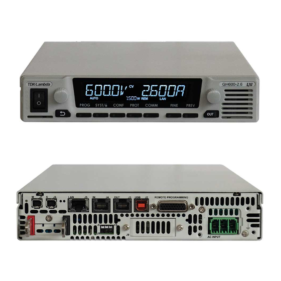
MODBUS TCP Interface Option Rear Panel View The power supply rear panel, with the MODBUS TCP option installed, is shown below: Link/Activity LED Link/Activity LED (Port 1) (Port 2) Network Status Module Status LEDs LEDs MODBUS TCP MODBUS TCP RJ45 Port 1 RJ45 Port 2 Figure 3–1: Rear Panel MODBUS TCP View Network Status LEDs... -
Page 14: Chapter 4: Connect To Network
CHAPTER 4: CONNECT TO NETWORK Ethernet Cable The Ethernet cable must be supplied by the customer. It may be a standard straight “patch” CAT-5 (or better) network cable or a “crossover” cable. Cable type is auto-detected by the power supply. NOTE The serial link (RS-485) cable (0.5 meters long) provided with the power supply cannot be used... -
Page 15: Power-Up The Modbus Tcp Power Supply
Power-up the MODBUS TCP Power Supply The power supply MODBUS TCP option automatically detects if it is connected or disconnected from a network. It automatically searches for a network server and receives or creates an IP address (set manually). It will also broadcast its IP address and hostname to all other devices on the network. 1. -
Page 16: Hostname
Hostname The hostname is an address in the form of name instead of IP address (i.e. G10-170). This address mode is less common than the IP address because the hostname cannot be viewed from the front panel, and because a naming service (such as NetBIOS or DNS) must be running on the network or the host PC. The default hostname has the following format: <... -
Page 17: Chapter 5: Modbus Tcp Setup
CHAPTER 5: MODBUS TCP SETUP View the IP and MAC Addresses When the power supply is operating with the MODBUS TCP enabled, IP and MAC addresses may be viewed on the front panel. To view the IP and MAC addresses, perform the following steps: To view the IP address: Press COMM button. -
Page 18: Modbus Tcp Reset
To change the IP address: Press COMM button. Rotate Voltage Encoder until IP appears on the Voltage display, 1 appears on the Current display. Press Current encoder to enter IP configuration. Rotate Voltage encoder to view the IP address. Voltage display shows IP1-IP4 by rotating Voltage encoder. The Current display shows the corresponding IP address. -
Page 19: Chapter 6: Web Pages
CHAPTER 6: WEB PAGES Benefits of Web Pages web pages are useful for: Read Ethernet configuration, statistics and verify communication with the power supply. • Configuring the LAN connection. • Opening the Overview Page Once the rear Module Status LED turns Green and Network Status LED turns Green or Flashing Green (refer to Section 3.3 for LEDs overview), the web page is accessible. -
Page 20: Module Overview Page
MODULE Overview Page The following page appears when the web page is opened for the first time or when it is refreshed: Figure 6–3: Overview Page Overview page contains basic information related to the optional module name (communication type), serial number, FW (firmware) revision, operation time since last communication enable (uptime) and internal (optional card only) CPU load. -
Page 21: Interface Counters View
Figure 6–5: Ethernet Settings and Status View 6.5.2 Interface Counters View Interface Counters view provides general information related to internal input output counters. Figure 6–6: Interface Counters View 6.5.3 Media Counters View Media Counters view provides general information related to media input output counters. These counters summarize TCP protocol media errors. -
Page 22: Modbus Tcp Statistics View
6.5.4 MODBUS TCP Statistics View MODBUS TCP Statistics view provides general information related to MODBUS TCP packets transfer. These counters summarize MODBUS TCP protocol errors. Figure 6–8: MODBUS TCP Statistics View NETWORK Configuration Page The Configuration page provides the ability to modify Ethernet configuration parameters. Figure 6–9: Network Configuration View IP Configuration section provides the ability to Enable/Disable DHCP (Dynamic Host... -
Page 23: Services Smtp Page
• Auto – Auto Negotiation enabled. Speed and duplex are configured automatically according to the network the power supply is connected to. 10 HDX – 10Mbps, Half Duplex configuration. • • 10 FDX – 10Mbps, Full Duplex configuration. 100 HDX – 100Mbps, Half Duplex configuration. •... -
Page 24: Chapter 7: Programming Using Sockets
CHAPTER 7: PROGRAMMING USING SOCKETS Socket Description MODBUS TCP offers socket connections. Socket is a low-level protocol that is universally available in all operating systems and programming environments. Communicating Using Sockets Communicating through sockets involves opening a socket connection, sending commands (MODBUS TCP register address, and parameter) and reading the responses. -
Page 25: Chapter 8: Connecting Over Wan
CHAPTER 8: CONNECTING OVER WAN To connect over the Wide Area Network (i.e.: the global internet), the following settings must be made in the network server. View Web Pages Over WAN power supply MODBUS TCP interface has a server for running the web pages. The web server is listening in Port 80. -
Page 26: Chapter 9: Modbus Tcp Data Structure
CHAPTER 9: MODBUS TCP DATA STRUCTURE Programming / Monitoring Values Translation MODBUS TCP communication interface preserves power supply resolution and accuracy, according to specifications. Programming / Monitoring values are represented in a form of 16 bits unsigned integer value. Rated Voltage, Current and Power (nominal values) are represented as 53620 in a decimal base or 0xD174 in a hexadecimal base. -
Page 27: Data Type
Char data type is used for strings represented as ASCII characters. Size of char is 1 byte. Char data type example - *IDN? query (address 3, 100 bytes, 50 registers) for 100 Volts, 50 Amperes power supply: TDK-LAMBDA,G100-50-MODBUS,12345-123456,G:02.000. Register Address... - Page 28 NOTES 1. * Last 0 is added as the initial register value is 0, this value is not part of the *IDN? string. 2. Always start register access from the first register address according to commands mapping table (refer to Section 9.7) for each command / query. Access to any other register won’t represent the actual data. For example for *IDN? query, always read from address 3.
-
Page 29: Data Access
Data Access MODBUS TCP supports three types of data access operations: Read, Write and Read/Write. Query commands (registers) have Read access only. NOTES 1. Register which don’t have Read access return 0. 2. Write of an out of range value results in an error. It is recommended to read register 935 (SYSTem:ERRor? query) to verify no errors. -
Page 30: Registers Mapping
NOTE Read / Write coils (operation function codes 0x01 and 0x05) operations are not supported Registers Mapping MODBUS TCP registers are mapped according to the table below. Refer to USER MANUAL (IA761-04-02_) for information regarding commands functionality. *CLS uint16 0-255 *ESE uint16 0-255... - Page 31 0-53620 MEASure:VOLTage[:DC]? uint16 0-53620 MEASure:CURRent[:DC]? uint16 0-53620 MEASure:POWer[:DC]? uint16 OUTPut[:STATe] uint16 OUTPut:ENA[:STATe] uint16 OUTPut:ENA:POLarity uint16 OUTPut:ILC[:STATe] uint16 OUTPut:MODE? uint16 OUTPut:PON[:STATe] uint16 OUTPut:PROTection:CLEar uint16 OUTPut:PROTection:FOLDback[:MODE] uint16 1-255 OUTPut:PROTection:FOLDback:DELay uint16 OUTPut:RELay1[:STATe] uint16 OUTPut:RELay2[:STATe] uint16 OUTPut:TTLTrg:MODE uint16 0,1-9999 [PROGram]:COUNter uint16 0-53620 [PROGram]:LIST:CURRent uint16 Upload [PROGram]:LIST:CURRent registers uint16 0.001-129600...
- Page 32 0-51065 [SOURce]:VOLTage:PROTection:LOW[:LEVel] uint16 0.0001-999.99 [SOURce]:CURRent:SLEW:DOWN float 0.0001-999.99 [SOURce]:CURRent:SLEW:UP float 0.0001-999.99 [SOURce]:VOLTage:SLEW:DOWN float 0.0001-999.99 [SOURce]:VOLTage:SLEW:UP float [SOURce]:POWer:STATe uint16 1-53620 [SOURce]:POWer[:LEVel] uint16 0,1,2 [SOURce]:VOLTage:MODE uint16 0,1,2 [SOURce]:VOLTage:EXTernal:MODE uint16 0,1,2 [SOURce]:CURRent:MODE uint16 0,1,2 [SOURce]:CURRent:EXTernal:MODE uint16 [SOURce]:CURRent:EXTernal:LIMit[:STATe] uint16 0-65535 STATus:OPERation[:EVENt]? uint16 0-65535 STATus:OPERation:CONDition? uint16 0-65535 STATus:OPERation:ENABle uint16...
-
Page 33: Modbus Tcp Unique Commands Structure
1010 TRIGger[:IMMediate] uint16 1011 0-10000 TRIGger:DELay uint16 1012 TRIGger:SOURce uint16 1013 SYSTem:PARallel:ACKNowledge uint16 1014 ASCII SYSTem:DATE? char 1021 SYSTem[:COMMunicate]:WATCHdog:STATe uint16 1022 1-3600 SYSTem[:COMMunicate]:WATCHdog:TIMe uint16 NOTES 1. Size of each register: 2 bytes. 2. An out of range parameter might result in an unpredicted behavior of the power supply. 3. - Page 34 *OPC Parameter To activate, write 0x0001 as parameter. *OPT? Returns Returns 2 for MODBUS TCP interface. *RST Parameter To activate, write 0x0001 as parameter. *TRG Parameter To activate, write 0x0001 as parameter. *WAI Parameter To activate, write 0x0001 as parameter. ABORt Parameter To activate, write 0x0001 as parameter.
- Page 35 OUTPut:TTLTrg:MODE Parameter OFF - 0x0000; FSTR – 0x0001; TRIG - 0x0002 as return value. [PROGram]:COUNter Parameter INFinity – write 0x0000; Number of iterations - write 1-9999 as parameter. Any value above 9999 results in INFinity. [PROGram]:LIST:CURRent Parameter Each value is loaded into a single register. Refer to Section 9.9 for an example of Voltage registers.
- Page 36 [PROGram]:WAVE:TIME Parameter Each value is loaded into a pair of registers. Low address value holds the least significant part. Refer to Section 9.9 for an example of List Dwell registers. Upload [PROGram]:WAVE:TIME registers Specific MODBUS TCP specific command used to upload [PROGram]:WAVE:TIME into power supply.
- Page 37 [SOURce]:VOLTage:EXTernal:MODE Parameter DIG - 0x0000; VOL - 0x0001; RES - 0x0002 as return value. [SOURce]:CURRent:MODE Parameter NONE - 0x0000; LIST - 0x0001; WAVE - 0x0002 as return value. [SOURce]:CURRent:EXTernal:MODE Parameter DIG - 0x0000; VOL - 0x0001; RES - 0x0002 as return value. SYSTem[:COMMunicate]:BAUDrate? Return 9600 - 0x0000;...
-
Page 38: Sequencer Activation
TRIGger:DELay Unit mSec. Data is represented in milliseconds. For example: 1 equals 1mSec; 1000 equals 1Sec. TRIGger:SOURce Parameter BUS - 0x0000; EXT - 0x0001 as return value. NOTES 1. LAN specific commands are not available for MODBUS TCP interface. 2. SYSTEM[:COMMunicate]:LANGuage command is not available for MODBUS TCP interface. 3. - Page 39 INIT:CONT OFF Trigger system is enabled for a single trigger action INIT Trigger initialize *TRG Trigger command MODBUS TCP Registers programming: Write 0x0001 to register 920 Select LIST Mode Sequence Write 0x29E4 to register 396 Set voltage value 2 Volts Write 0x53C8 to register 397 Set voltage value 4 Volts Write 0x29E4 to register 398...
-
Page 40: Chapter 10: Multi Drop Connection
CHAPTER 10: MULTI DROP CONNECTION One MODBUS TCP Interface can control more than one power supply. A maximum of 31 units can be connected via RS485 interface to a power supply with the installed MODBUS TCP option. The power supply connected to a PC via the Ethernet cable must be configured to MODBUS TCP (OPT) communication interface, the other units must be configured to RS485 interface. - Page 41 NOTES ____________________________________________ ____________________________________________ ____________________________________________ ____________________________________________ ____________________________________________ ____________________________________________ ____________________________________________ ____________________________________________ ____________________________________________ ____________________________________________ ____________________________________________ ____________________________________________ ____________________________________________ ____________________________________________ ____________________________________________ ____________________________________________ ____________________________________________ ____________________________________________ ____________________________________________ ____________________________________________ ____________________________________________ ____________________________________________ ____________________________________________ ____________________________________________ ____________________________________________ ____________________________________________ ____________________________________________ ____________________________________________ ____________________________________________...
- Page 42 NOTES ____________________________________________ ____________________________________________ ____________________________________________ ____________________________________________ ____________________________________________ ____________________________________________ ____________________________________________ ____________________________________________ ____________________________________________ ____________________________________________ ____________________________________________ ____________________________________________ ____________________________________________ ____________________________________________ ____________________________________________ ____________________________________________ ____________________________________________ ____________________________________________ ____________________________________________ ____________________________________________ ____________________________________________ ____________________________________________ ____________________________________________ ____________________________________________ ____________________________________________ ____________________________________________ ____________________________________________ ____________________________________________ ____________________________________________...
- Page 43 NOTES ____________________________________________ ____________________________________________ ____________________________________________ ____________________________________________ ____________________________________________ ____________________________________________ ____________________________________________ ____________________________________________ ____________________________________________ ____________________________________________ ____________________________________________ ____________________________________________ ____________________________________________ ____________________________________________ ____________________________________________ ____________________________________________ ____________________________________________ ____________________________________________ ____________________________________________ ____________________________________________ ____________________________________________ ____________________________________________ ____________________________________________ ____________________________________________ ____________________________________________ ____________________________________________ ____________________________________________ ____________________________________________ ____________________________________________...
- Page 44 NOTES ____________________________________________ ____________________________________________ ____________________________________________ ____________________________________________ ____________________________________________ ____________________________________________ ____________________________________________ ____________________________________________ ____________________________________________ ____________________________________________ ____________________________________________ ____________________________________________ ____________________________________________ ____________________________________________ ____________________________________________ ____________________________________________ ____________________________________________ ____________________________________________ ____________________________________________ ____________________________________________ ____________________________________________ ____________________________________________ ____________________________________________ ____________________________________________ ____________________________________________ ____________________________________________ ____________________________________________ ____________________________________________ ____________________________________________...
Need help?
Do you have a question about the Genesys Series and is the answer not in the manual?
Questions and answers